Table of Contents
Advertisement
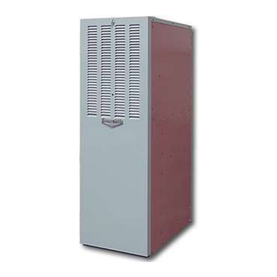
OIL FIRED FURNACE
INSTALLATION AND OPERATION MANUAL
WITH USERS INFORMATION SECTION
MODELS:
OL6FA072D48(B/R/C)
OL6RA072D48(B/R/C)
OL6FA072DV5(B/R/C)
OL6RA072DV5(B/R/C)
OL8FA119T60(B/R/C)
OL8RA119T60(B/R/C)
c WARNING: IF THE INFORMATION IN THESE INSTRUCTIONS IS NOT FOLLOWED EXACTLY, A FIRE OR
EXPLOSION MAY RESULT CAUSING PROPERTY DAMAGE, PERSONAL INJURY, OR LOSS OF LIFE.
DO NOT STORE OR USE GASOLINE OR OTHER FLAMMABLE VAPORS AND LIQUIDS IN THE VICINITY OF THIS
OR ANY OTHER APPLIANCE.
c WARNING: IMPROPER INSTALLATION, ADJUSTMENT, ALTERATION, SERVICE, OR MAINTENANCE CAN
CAUSE INJURY OR PROPERTY DAMAGE. REFER TO THIS MANUAL. FOR ASSISTANCE OR ADDITIONAL
INFORMATION CONSULT A QUALIFIED INSTALLER, OR SERVICE AGENCY.
c AVERTISSEMENT: SI L'INFORMATION DANS CES INSTRUCTIONS N'EST PAS SUIVI À LA LETTRE, UN
INCENDIE OU UNE EXPLOSION ENTRAÎNANT DES DOMMAGES MATÉRIELS, DES BLESSURES CORPORELLES
OU DES PERTES DE VIE.
NE PAS ENTREPOSER NI UTILISER D'ESSENCE OU AUTRES VAPEURS ET LIQUIDES INFLAMMABLES À
PROXIMITÉ DE CET APPAREIL OU DE TOUT AUTRE APPAREIL.
c AVERTISSEMENT: UNE MAUVAISE INSTALLATION, D'AJUSTEMENT, DE LA MODIFICATION,
D'ENTRETIEN OU DE MAINTENANCE PEUVENT CAUSER DES BLESSURES OU DOMMAGES MATÉRIELS,
REPORTEZ-VOUS À CE MANUEL POUR OBTENIR DE L'AIDE OU DES RENSEIGNEMENTS SUPPLÉMENTAIRES,
CONSULTER UN INSTALLATEUR QUALIFIÉ, OU ORGANISME DE SERVICE.
PLEASE READ THESE INSTRUCTIONS PRIOR TO INSTALLATION, INITIAL FIRING, AND BEFORE
PERFORMING ANY SERVICE OR MAINTENANCE. THESE INSTRUCTIONS MUST BE LEFT WITH THE
USER AND SHOULD BE RETAINED FOR FUTURE REFERENCE BY QUALIFIED SERVICE PERSONNEL.
VEUILLEZ LIRE CES INSTRUCTIONS AVANT L'INSTALLATION, LES PREMIERS TIRS, ET AVANT
D'EFFECTUER TOUT ENTRETIEN OU MAINTENANCE. CES INSTRUCTIONS DOIVENT ÊTRE LAISSÉS
AVEC L'UTILISATEUR ET DEVRAIT ÊTRE CONSERVÉ POUR RÉFÉRENCE FUTURE PAR UN TECHNICIEN
QUALIFIÉ.
THERMO PRODUCTS, LLC.
PO BOX 237
DENTON, NC 27239
PHONE: 800-476-4328
(OL6 SERIES)
(OL8 SERIES)
MO-547
ECN 5539-MA 200902
Made IN USA
Advertisement
Table of Contents

Related Manuals for Thermo Pride OL6FA072D48B


Summary of Contents for Thermo Pride OL6FA072D48B
- Page 1 OIL FIRED FURNACE INSTALLATION AND OPERATION MANUAL WITH USERS INFORMATION SECTION MODELS: OL6FA072D48(B/R/C) OL6RA072D48(B/R/C) OL6FA072DV5(B/R/C) OL6RA072DV5(B/R/C) OL8FA119T60(B/R/C) OL8RA119T60(B/R/C) c WARNING: IF THE INFORMATION IN THESE INSTRUCTIONS IS NOT FOLLOWED EXACTLY, A FIRE OR EXPLOSION MAY RESULT CAUSING PROPERTY DAMAGE, PERSONAL INJURY, OR LOSS OF LIFE. DO NOT STORE OR USE GASOLINE OR OTHER FLAMMABLE VAPORS AND LIQUIDS IN THE VICINITY OF THIS OR ANY OTHER APPLIANCE.
-
Page 3: Safety Section
All installations and services must be performed by qualified service personnel. I. SAFETY SECTION This page contains various warnings and cautions found throughout the Oil Furnace Manual. Please read and comply with the statements below. cWARNING AND CAUTIONS: cWARNING: This furnace is not to be used as a construction heater. See Page 1. c CAUTION MUST BE TAKEN NOT TO EXCEED 90°... -
Page 4: Table Of Contents
All installations and services must be performed by qualified service personnel. TABLE OF CONTENTS SECTION BEGINNING PAGE I. SAFETY SECTION II. GENERAL INSTRUCTIONS A. VENTING B. DRAFT REGULATORS C. DUCT WORK/AIR CONDITIONING/SUPPLY/RETURN AIRFLOW AND AIR TEMPERATURE D. AIR FILTERS E. LIMIT POSITION F. -
Page 5: General Instructions
All installations and services must be performed by qualified service personnel. II. GENERAL INSTRUCTIONS - READ BEFORE START OF INSTALLATION The heating output capacity of the furnace proposed for installation should be based on a heat loss calculation made according to the manuals provided by the Air Conditioning Contractors of America (ACCA) or the American Society of Heating, Refrigeration and Air Conditioning Engineers, Inc. - Page 6 All installations and services must be performed by qualified service personnel. Table 1: MINIMUM CLEARANCES TO COMBUSTIBLE MATERIALS FROM TOP & TYPE MODEL NO. FRONT FROM SIDES OF SIDES FURNACE UNIT FLUE/VEN PLENUM Lowboy OL6**072D*** 0” 6” ‡ 1” 7” 0”...
-
Page 7: Draft Regulators
All installations and services must be performed by qualified service personnel. A. FLUE / CHIMNEY / VENT CONNECTOR c CAUTION: DO NOT install a manual damper in the chimney or vent connector. Thermally- activated type vent dampers are NOT recommended for use on these furnaces. It is desirable to install the shortest vent connector (also referred to as a flue or chimney connector) possible with the fewest number of fittings, i.e. - Page 8 All installations and services must be performed by qualified service personnel. Direct (Side-Wall) Venting The furnace may also be horizontally vented through a sidewall. Thermo Products has available the side wall vent kits for such applications. When installing the sidewall vent kits, outside combustion air must also be applied to the burner.
-
Page 9: Duct Work/Air Conditioning/Supply/Return Airflow And Air Temperature
All installations and services must be performed by qualified service personnel. C. DUCT WORK/AIR CONDITIONING/SUPPLY/RETURN AIRFLOW AND AIR TEMPERATURE: If the furnace is used in connection with summer air conditioning (cooling), the furnace should be installed parallel with or on the upstream side of the evaporator coil to avoid condensation in the furnace heat exchanger. -
Page 10: Air Filters
If a method other than internal Thermo Pride filter rack is selected for retention of the filters and/or use of a different filter type is desired, refer to Table 4 below for minimum sizing guidelines for selecting filter for the unit. -
Page 11: Limit Position
All installations and services must be performed by qualified service personnel. NOTICE: Any internal stiffeners used in the filter must not be removed, although they can be cut to size as needed. E. LIMIT POSITION The limit in these furnaces are fixed and cannot be relocated. F. - Page 12 A fiber insulating sleeve or amulet is provided on the burner tube of specific Thermo Pride burners.(see Fig. 4). See Thermo Pride burner application chart for type of insulator. Do not allow the burner tube or end cone to physically touch or protrude into the chamber, as excess heat transfer could result in destruction of the tube, end cone or both.
-
Page 13: Burner Specifications And Applications
All installations and services must be performed by qualified service personnel. G. BURNER SPECIFICATIONS AND APPLICATIONS: Beckett oil burner application HEAD STATIC THERMO BECKETT MAXIMUM SHIPPED OIL PUMP PRIDE’S BURNER PLATE NOZZLE NOZZLE PRESSURE FURNACE SIZE** BURNER MODEL & (PSIG) SIZE MODEL TUBE... - Page 14 All installations and services must be performed by qualified service personnel. For more specific burner information, contact: Thermo Products, LLC PO Box 237 Denton, NC 27239 800-348-5130 OIL NOZZLE CAPACITY CHART NOZZLE SIZE (GPH) EFFECTIVE EQUIVALENT HEATING HEAT INPUT UNITS CAPACITY** Beckett Carlin...
-
Page 15: Heat Exchanger Cleaning Instructions
All installations and services must be performed by qualified service personnel. H. HEAT EXCHANGER CLEANING INSTRUCTIONS: cWARNING: THE HEAT EXCHANGER MUST BE CLEANED BY A QUALIFIED SERVICE PERSON. It is important to inspect and clean the heat exchanger once a year, or as necessary, to remove any build-up of soot. -
Page 16: Fan Control Boards
All installations and services must be performed by qualified service personnel. I. FAN CONTROL BOARDS: Thermo Pride oil furnaces can be equipped with one of the following two boards. Please refer to Fig. 7 to see which board you have. - Page 17 All installations and services must be performed by qualified service personnel. Operating Modes for UT board (PSC) Standby Mode All outputs are off and the control is waiting for a thermostat demand. The thermostat inputs, and limit switch are continuously monitored. The control initiates action when a thermostat call is received or limit switch opens.
- Page 18 All installations and services must be performed by qualified service personnel. Heat Mode When a call for heat (“W”) is received from the thermostat, if the “Cool” mode is not already active, the “T-T” terminal is energized and the blower on delay is started. The on-off pattern of DIP switch SW2 (positions 1 and 2) select one of four blower on delay values (see Table 6).
- Page 19 All installations and services must be performed by qualified service personnel. Motor Blower Speed Three interconnected blower speed outputs are provided. A “G” call for fan will provide power to the LOW speed tap only. A “W” heat call will provide power to the Heat speed tap only.
- Page 20 All installations and services must be performed by qualified service personnel. The red Board Status LED has two functions: It will light when the board recognizes a valid input signal and will stay lit until all valid signals are removed. This is intended to show that the board is functioning and able to respond to input signals.
- Page 21 All installations and services must be performed by qualified service personnel. Heat Mode When a call for heat (“W”) is received from the thermostat, if the “Cool” mode is not already active, the “T-T” terminal is energized and the blower on delay is started. The on-off pattern of DIP switch SW2 (positions 1 and 2) select one of four blower on delay values (see Table 7).
- Page 22 All installations and services must be performed by qualified service personnel. The speed taps are interconnected and interlocked, only one speed may be powered at any one time. When a speed is to be operated, the speed select relays are operated to select the path to the motor tap and then the enable relay is operated to switch the operating power to the selected motor speed tap.
-
Page 23: Users Information Section
All installations and services must be performed by qualified service personnel. III. USERS INFORMATION SECTION A. OIL SUPPLY: Do not allow the fuel tank to run completely empty. During the summer, keep the tank full to prevent condensation of moisture on the inside surface of the tank. If the fuel tank runs completely dry, it may be necessary to purge the lines of trapped air. -
Page 24: Starting The Burner
All installations and services must be performed by qualified service personnel. cCAUTION: DO NOT ATTEMPT TO START THE BURNER WHEN: 1. Excess oil has accumulated, 2. The furnace is full of vapors 3. The combustion chamber is very hot. IF ONE OR MORE OF THESE CONDITIONS EXIST, CONTACT A QUALIFIED SERVICE PERSON. - Page 25 All installations and services must be performed by qualified service personnel. COMBUSTION AND EFFICIENCY TESTING FOR OIL FIRED CENTRAL FURNACES.
- Page 26 All installations and services must be performed by qualified service personnel. Appendix – A Replacement Parts: Replacement Parts for OL6F*072D*...
- Page 27 All installations and services must be performed by qualified service personnel.
- Page 28 All installations and services must be performed by qualified service personnel. Replacement Parts for OL6R*072D**...
- Page 29 All installations and services must be performed by qualified service personnel.
- Page 30 All installations and services must be performed by qualified service personnel. Replacement Parts for OL8FA119T60...
- Page 31 All installations and services must be performed by qualified service personnel.
- Page 32 All installations and services must be performed by qualified service personnel. Replacement Parts for OL8RA119T60...
- Page 33 All installations and services must be performed by qualified service personnel.
- Page 34 All installations and services must be performed by qualified service personnel.
- Page 35 All installations and services must be performed by qualified service personnel.
- Page 36 All installations and services must be performed by qualified service personnel.
- Page 37 All installations and services must be performed by qualified service personnel.
- Page 38 All installations and services must be performed by qualified service personnel.
- Page 39 All installations and services must be performed by qualified service personnel.
- Page 40 All installations and services must be performed by qualified service personnel. All installations and services must be performed by qualified service personnel. Appendix – B Wiring Diagrams OL6*A072D48 PSC (NRGMAX Control) Wiring Diagram...
- Page 41 All installations and services must be performed by qualified service personnel. OL6*A072DV5 ECM (NRGMAX Control) Wiring Diagram...
- Page 42 All installations and services must be performed by qualified service personnel. OL6*A072D48 PSC (UT Control) Wiring Diagram...
- Page 43 All installations and services must be performed by qualified service personnel. OL6*A072DV5 ECM (UT Control) Wiring Diagram Note: Refer to ECM Operation Manual supplied with furnace for ECM models...
- Page 44 All installations and services must be performed by qualified service personnel. OL8*A119T60 CTM (NRGMAX Control) Wiring Diagram...
- Page 45 All installations and services must be performed by qualified service personnel. OL8*A119T60 CTM (UT control) Wiring Diagram...
- Page 46 All installations and services must be performed by qualified service personnel. Appendix – C Airflow Charts OL6*A072D48 ALTERATIONS REQ’D FOR A/C @ DESIGN EXTERNAL STATIC PRESSURE HTG Speed by Input COOLING UNIT Low fire Mid Fire High Fire Recommended CLG Speed 24,000 Med Low 30,000...
- Page 47 All installations and services must be performed by qualified service personnel. OL6*A072DV5 Heating Speed Set-ups Furnace Motor Current Draw (Amps/ / Watts) vs. External Static Pressure (in W.C.) Low Fire Med Fire High Fire BTUH 60,000 72,000 90,000 Control SW 1 Switch Heating Aprox.
- Page 48 All installations and services must be performed by qualified service personnel. OL6*A072DV5 Cooling Speed Set-ups Furnace Motor Current Draw (Amps / Watts) vs. External Static Pressure (in W.C) Air Flow Control SW 1 Switch Clg. Settings Tonnage Cool Continuous 6-OFF 1.2/100 1.9/162 5-OFF...
- Page 49 All installations and services must be performed by qualified service personnel. OL8FA119T60 ALTERATIONS REQ’D FOR A/C @ DESIGN EXTERNAL STATIC PRESSURE COOLING UNIT HTG Speed by Input Recommended CLG Speed High Fire Fire Fire 36,000 42,000 MED LOW 48,000 MED HIGH 60,000 HIGH AS SHIPPED CLG.
- Page 50 All installations and services must be performed by qualified service personnel. OL8RA119T60...
Need help?
Do you have a question about the OL6FA072D48B and is the answer not in the manual?
Questions and answers