Table of Contents
Advertisement
INSTALLATION AND OPERATION MANUAL
OL6RA072D48(B/R/C)
OL6RA072DV5(B/R/C)
c WARNING: IF THE INFORMATION IN THESE INSTRUCTIONS IS NOT FOLLOWED EXACTLY, A
FIRE OR EXPLOSION MAY RESULT CAUSING PROPERTY DAMAGE, PERSONAL INJURY, OR
LOSS OF LIFE.
DO NOT STORE OR USE GASOLINE OR OTHER FLAMMABLE VAPORS AND LIQUIDS IN THE
VICINITY OF THIS OR ANY OTHER APPLIANCE.
c WARNING: IMPROPER INSTALLATION, ADJUSTMENT, ALTERATION, SERVICE, OR
MAINTENANCE CAN CAUSE INJURY OR PROPERTY DAMAGE. REFER TO THIS MANUAL. FOR
ASSISTANCE OR ADDITIONAL INFORMATION CONSULT A QUALIFIED INSTALLER, OR SERVICE
AGENCY.
PLEASE READ THESE INSTRUCTIONS PRIOR TO INSTALLATION, INITIAL FIRING, AND BEFORE
PERFORMING ANY SERVICE OR MAINTENANCE. THESE INSTRUCTIONS MUST BE LEFT WITH
THE USER AND SHOULD BE RETAINED FOR FUTURE REFERENCE BY QUALIFIED SERVICE
PERSONNEL.
MO-483
ECN 5550-MA 180910
OIL FIRED FURNACE
WITH USERS INFORMATION SECTION
MODEL:
THERMO PRODUCTS, LLC.
PO BOX 217
NORTH JUDSON, IN 46366
PHONE: 800-476-4328
OL6FA072D48(B/R/C)
OL6FA072DV5(B/R/C)
Made IN USA
Advertisement
Table of Contents

Subscribe to Our Youtube Channel
Related Manuals for Thermo Pride OL6RA072D48


Summary of Contents for Thermo Pride OL6RA072D48
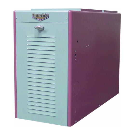
- Page 1 OIL FIRED FURNACE INSTALLATION AND OPERATION MANUAL WITH USERS INFORMATION SECTION MODEL: OL6RA072D48(B/R/C) OL6FA072D48(B/R/C) OL6RA072DV5(B/R/C) OL6FA072DV5(B/R/C) c WARNING: IF THE INFORMATION IN THESE INSTRUCTIONS IS NOT FOLLOWED EXACTLY, A FIRE OR EXPLOSION MAY RESULT CAUSING PROPERTY DAMAGE, PERSONAL INJURY, OR LOSS OF LIFE.
-
Page 3: Table Of Contents
CONTENTS SECTION PAGE I. SAFETY SECTION A. CODES AND CLEARANCES B. MAKE-UP AIR II. GENERAL INSTRUCTIONS A. CHIMNEY B. VENTING C. DRAFT REGULATORS D. DUCT WORK/AIR CONDITIONING E. AIR FILTER(S) F. LIMIT POSITION AND LOCATION G. BURNER INSTALLATION H. BURNER SPECIFICATIONS AND APPLICATIONS OILTANK AND PIPING J. - Page 5 Model Number Digit 9 10 11 12 Oil Furnace Model Nomenclature Example Model Numbers 2 D V 2 D V O = Oil H = Highboy D = Downflow L= Lowboy 6 = Heat Exchanger Size Identifier F = Front R = Rear A = Single Stage Heating Capacity MBTUH (000's) with factory installed nozzle...
-
Page 6: Safety Section
This furnace is not to be used as a construction heater. See Page 3 cWARNING: The predetermined limit locations on all of the Thermo Pride oil fired furnaces have been tested and approved by Thermo Products, LLC. Any attempt to... -
Page 8: Codes And Clearances
At the time of installation, the unit will require connection to electric power, fuel oil supply, and supply and return air ductwork. In the event of a shortage of parts or damage, contact Thermo Pride office. This unit uses a fan-assisted combustion system, consisting of a pressure atomizing, oil burner and combustion air blower, used to push the products of combustion through the heat exchanger system. -
Page 9: Make-Up Air
4. Definitions of "combustible" and "non-combustible" materials as presented in the 1996 version of the National Fuel Gas Code, ANSI Z223.1-1996/NFPA 70-1996, are as follows: a. Combustible material: “...materials made of or surfaced with wood, compressed paper, plant fibers, or other materials that are capable of being ignited and burned. -
Page 10: General Instructions
The Thermo Pride Make-Up-Air Control, installs quickly and easily on any warm air heating system, delivers controlled, fresh air automatically during the winter and a constant supply of clean, fresh air for comfortable summer living. -
Page 11: Chimney
The following are common chimney requirements necessary for the furnace to operate correctly: A masonry chimney serving a Thermo Pride oil fired furnace must comply with local codes and NFPA Standard for Chimneys, Fireplaces, Vents, and Solid Fuel Burning Appliances (NFPA211-1996 or latest edition). - Page 12 2. PROPER CHIMNEY HEIGHT: The chimney shall terminate at least 3 feet above the highest point where it passes through the roof of a building and at least 2 feet higher than any portion of a building within a horizontal distance of 10 feet. (See Fig.
- Page 13 Fig. 4: Proper insertion of the vent connector in the chimney. 4. PROPER CHIMNEY BOTTOM LEVEL: In cases where the chimney extends to the basement floor, the draft can usually be improved by filling the base of the chimney with sand to within 12 inches of the vent connector pipe after relocating the clean-out door.
- Page 14 Fig. 6: Suggested method to accommodate vent connector passage through a wall composed of a combustible material. Fig. 7: Alternate constructions that allow reduced clearances to combustible materials. REDUCTION OF CLEARANCES WITH SPECIFIED FORMS OF PROTECTION: Type of protection applied to and covering all surfaces of combustible material within the distance specified as the required clearance with no protection unless otherwise noted, all dimensions in inches, refer to Fig.
-
Page 15: Venting
The vent connector pipe between the furnace and chimney shall be of equal diameter as the flue outlet of the furnace. The vent connector pipe must be made of 24 gauge (or thicker) corrosion-resistant steel. The vent connector pipe should be as short as possible and installed so that it has a continuous rise from the furnace to the chimney. -
Page 16: Draft Regulators
The side wall vent may be installed either through the knock-out on the right or left side casing of the unit or vertically out the top opening of the vestibule. The combustion air inlet can be installed through either the lower left side casing knockout or the lower right side casing knockout. - Page 17 Airflow Requirements and Sizing of Duct Work: The duct system must be sized and installed by a qualified installer or service person, following the design standards of the Air Conditioning Contractors of America (ACCA) or the American Society of Heating, Refrigeration, and Air Conditioning Engineers (ASHRAE). This furnace has been designed to operate against a maximum external static pressure of 0.5 in.
- Page 18 Select values for the pressure drops of both the supply and return air systems. Each branch of the supply (or the return) air system will have this pressure drop. The total pressure drop of the supply and return air systems added together cannot exceed the maximum external static pressure that can be supplied by the appliance blower.
- Page 19 Table 3: Suggested Duct Sizes for Homes, Quiet Offices, Or Similar Installations (Based on a 0.1 in. W.G. static pressure drop per 100 ft. of duct.) 7. The supply and return air ducts, or flexible joints, should be carefully secured and sealed to the appliance housing to prevent air leakage from, or into, the duct system.
-
Page 20: Air Filter(S)
SIZING THE DUCT WORK FOR A COMBINATION HEATING AND COOLING SYSTEM: Two formulas must be used in determining the CFM requirements of a combustion heating and cooling system. 1. HEATING CFM: HEAT OUTPUT OF FURNACE (BTUH) 1.1 X TR (TEMPERATURE RISE, °F) = HEATING(CFM) EXAMPLES: A. -
Page 21: Limit Position And Location
If a method other than internal Thermo Pride filter rack is selected for retention of the filters and/or use of a different filter type is desired, refer to Table 4 below for minimum sizing guidelines for selecting filter for the unit. -
Page 22: Burner Installation
A fiber insulating sleeve or amulet is provided on the burner tube of specific Thermo Pride burners.(see Fig. 13). See Thermo Pride burner application chart for type of insulator. Do not allow the burner tube or end cone to physically touch or protrude into the chamber, as excess heat transfer could result in destruction of the tube, end cone or both. -
Page 23: Burner Specifications And Applications
H. BURNER SPECIFICATIONS AND APPLICATIONS: Beckett oil burner application THERMO BECKETT HEAD STATIC MAXIMUM SHIPPED PRIDE’S BURNER PLATE NOZZLE NOZZLE PUMP FURNACE MODEL BURNER MODEL & SIZE** SIZE PRESSURE SPEC NO. TUBE (PSIG) LENGTH OL6*A072D**B TP2501 AFG-4.5” 3-5/8 0.75X80 S 0.60X80... -
Page 24: Oiltank And Piping
I. OIL TANK AND PIPING: : All local codes and ordinances take precedence with regard to selection and installation of oil storage tank and oil supply (and return) lines. In the absence of local codes, all tanks and lines must be selected and installed according to the instructions in this manual and the Standard for the Installation of Oil-Burning Equipment, NFPA 31-1997, or the latest edition. -
Page 25: Oil Filter
When the oil tank is located below the level of the burner, it is necessary to “lift” the oil to the burner. A return line should be connected between the fuel pump and tank. This requires insertion of the "by-pass" plug into the fuel pump. - Page 26 Typically, control wiring between the appliance and the indoor thermostat, and if used, electronic air cleaner or humidifier, will be required. Field wiring of control circuits should consist of copper conductors rated for at least 15 amp service with an insulation temperature rating conforming to Type T wire, 35C temperature rise.
- Page 27 in conjunction with a humidistat to control a humidifier. These terminals are energized whenever the blower is active. Figure 15: The Fan Control Module NOTICE: It is important to confirm that the operating voltage of the humidifier or EAC being installed matches the output of this control.
- Page 28 Figure 16: Heat Anticipator Adjustment Scale In many cases, this setting can be found in the thermostat installation instructions. If this information is not available, or if the correct setting is questioned, the following procedures should be followed: Preferred method of adjustment: Using an analog ammeter on the lowest scale, such as an Amp Check, connect the meter across terminals “R”...
-
Page 29: Blower Setup
This formula can be used to calculate the correct setting for the adjustable heat anticipator: Ammeter reading = Anticipator Setting. No. of wire loops Or in this case, _2.5 A. = 0.25 A. (Anticipator Setting) 4. Adjust the position of the anticipator indicator to match the calculated ammeter setting. If a slightly longer cycle is desired, the pointer should be moved to a higher setting. - Page 30 Heating Speed Set-ups OL6*A072DV5 Furnace Motor Current Draw (Amps/ / Watts) vs. External Static Pressure (in W.C.) Low Fire Med Fire High Fire BTUH 60,000 72,000 90,000 Control SW 1 Switch Heating Aprox. Rise Aprox. Rise Aprox. Rise Settings 3-OFF 1.1/93 1.7/154 2-OFF...
- Page 31 Cooling Speed Set-ups OL6**072DV5 Furnace Motor Current Draw (Amps / Watts) vs. External Static Pressure (in W.C) Air Flow Control SW 1 Sw itch Clg. Setting Tonnage Cool Continuous 6-OFF 1.2/100 1.9/162 5-OFF 4-OFF 6-OFF 5-OFF 1017 1.8/155 2.5/223 4-ON 6-OFF 5-ON 1210...
- Page 32 For PSC systems, the ½ hp motor is equipped with 5 speeds. The unit is set for mid-fire temp rise @ 65ºF. See table for proper blower motor set up: OL6*A072D48 ALTERATIONS REQ’D FOR A/C @ DESIGN EXTERNAL STATIC PRESSURE HTG Speed by Input COOLING UNIT Low fire...
-
Page 33: Blower Controller Information For Psc Motor
Speed vs. color code for PSC Motor: Low = Orange Med-Low = Red Med= Blue Med-High = Yellow High = Black M. BLOWER CONTROLLER INFORMATION FOR PSC MOTOR (Note: for ECM blower controller information see: ECM Operation Manual document # Mo-440) TERMINAL DEFINITIONS &... - Page 34 A. Inputs Power supplies Line voltage is applied between the “S1” and “N1” quick connect terminals. 24 VAC Class II Transformer secondary voltage supplied to X and C Limit switch The 120 VAC optically isolated limit switch input is connected on pin P2-1 & 9. Refer to the Heat Mode section for the control operation.
- Page 35 EAC (electronic air cleaner) The control provides a 120 VAC output for an electronic air cleaner. This output is energized whenever the fan motor is energized (either low, heat or cool speed). Connection is made via male quick connect terminal labeled “EAC”. Humidifier The control provides a 120 VAC output for a humidifier.
- Page 36 Heat Mode When a call for heat (“W”) is received from the thermostat, if the “Cool” mode is not already active, the “T-T” terminal is energized and the blower on delay is started. The on-off pattern of DIP switch SW2 (positions 1 and 2) select one of four blower on delay values (see Table 11).
- Page 37 TROUBLE SHOOTING DIAGNOSTIC FEATURES The control board is equipped with 4 green Input Status LEDs and 1 red Board Status LED. These are intended to provide a quick view into furnace performance without requiring a voltmeter. The green Input Status LEDs are driven by the “Y”, “W”, “G”, and “DEHUM” inputs and are located directly below those inputs.
-
Page 38: Startup Procedures
N. STARTUP PROCEDURES: A. Heating System 1. Initial Startup: : Turn off power to furnace. Before the oil piping system is placed into service, it must have been leak tested by a qualified heating contractor. : For initial start-up of the appliance after installation, it may be necessary to purge the air out of the oil line. - Page 39 To Turn Off Oil to Appliance: Set the thermostat to the lowest setting and set the operating mode switch to “OFF”. If service is to be performed, turn off the electrical power to the appliance. iii. Turn the manual oil shutoff valve to the “OFF” position. 2.
- Page 40 Figure 19: Preliminary Adjustment of Burner Air Band and Air Shutter When ignition is established, make a preliminary burner air adjustment to attain a clean combustion flame. Generally, the burner bulk air band should be about 3/16 inch open and the opening of the burner air shutter set in the range of “2”...
- Page 41 operational tolerance is established allowing the burner to function well, even under less than ideal conditions. This results in less service and maintenance during a heating season. iii. FLUE GAS TEMPERATURE: The flue gas temperature will vary to some extent depending on the heat input rate, duct design, and the amount of air flow across the heat exchanger.
- Page 42 d. Note the oil pressure at the pump. e. To adjust the pressure, use a common screwdriver to turn in the pressure adjustment screw, located on the upper front of the oil pump body. f. Allow the fuel flow rate to stabilize for a moment. Recheck the oil pressure. g.
- Page 43 Block return air opening or disconnect blower motor leads. iii. Restore power to appliance. In the heating mode, set the thermostat above room temperature producing “a call for heat”. When high air temperatures are reached within the heating section, the high limit control should act to shutdown the burner.
-
Page 44: Users Information Section
NEVER burn garbage or refuse in your furnace. Never try to ignite oil by tossing burning papers or other material into your furnace. cWARNING: Thermo Pride oil furnaces are designed to burn No. 1 or No. 2 distillate fuel oil. NEVER USE GASOLINE OR A MIXTURE OF OIL AND GASOLINE. -
Page 45: Starting The Burner
D. STARTING THE BURNER: 1. Turn the main service switch to "OFF" position. 2. Set thermostat substantially above room temperature. 3. Open shut-off valves in oil supply line to burner. 4. Turn service switch to furnace "ON". If burner starts and runs, but stops again on lockout, it may be necessary to bleed the lines or make burner combustion air adjustments. -
Page 46: Installer's Instructions To User
IV. INSTALLER'S INSTRUCTIONS TO USER: After completing the installation, the installer shall inform and/or demonstrate to the homeowner the following items: 1. The location of these instructions. The instructions must be kept along with instructions for any accessories in the plastic pouch with the appliance. 2. -
Page 47: Dealer Maintenance
V. DEALER MAINTENANCE: SAFETY DURING SERVICING AND INSPECTION : Personal injury or property damage could result from repair or service of this appliance by anyone other than a qualified heating contractor. The user may only perform the activities described in the Homeowner/User Routine Maintenance section of this manual. : To avoid injury from moving parts, or electrical shock, shut off the power to the appliance before removing blower compartment door and servicing this appliance. -
Page 48: Heat Exchanger
B. HEAT EXCHANGER: cWARNING: A qualified heating contractor must clean the heat exchanger. At least once a year, inspect the heat exchanger for evidence of corrosion, pitting, warpage, deterioration, and carbon (soot) build-up. A layer of soot on the inside of the heat exchanger will act as an insulator and reduce heat transfer, resulting in less heating efficiency. - Page 49 Figure 24: Heat Exchanger Clean-Outs Vacuum Hose Length Fig. 25: Recommended method and device for cleaning inside of heat exchanger.
-
Page 50: Electrical System
4. Operational Check: cCAUTION: Before troubleshooting, familiarize yourself with the start up and check out procedures NOTICE: After reassembling the appliance, check for fuel oil leakage from the supply piping. a. Check proper operation of the ignition system and for proper combustion. b. -
Page 51: Extended Appliance Shutdown
Figure 26: Location of Supply/Return Air Filters Filter replacement: To ensure an adequate replacement filter is selected, should the filter require replacing, refer to Table 4, in Air Filters section of this manual, for the minimum filter areas required for different types of available filters. - Page 52 3. Fill the oil tank to reduce water condensation in the tank. 4. If the shutdown period will exceed one heating season, an oil stabilizer should be added to the oil tank. Consult your oil supplier for recommendations. ON STARTUP: 1.
-
Page 53: Homeowner/User Information And Routine Maintenance
VI. HOMEOWNER/USER INFORMATION AND ROUTINE MAINTENANCE: cWARNING: Never burn garbage or refuse in this appliance. Never try to ignite oil by tossing burning papers or other material into the combustion chamber. cWARNING: Oil-fired appliances produced by Thermo Products are designed for burning No. - Page 54 Beckett Burner Riello Burner Figure 28: Location of oil primary control reset button If this action does not reactivate the unit, contact a qualified service agency for assistance. In general, if the thermostat is set in the heating mode, the heating system functions entirely automatically.
-
Page 55: Troubleshooting
VII. TROUBLESHOOTING: THIS SECTION IS ONLY TO BE PERFORMED BY TRAINED, QUALIFIED SERVICE PERSONNEL, AND NOT BY THE FURNACE OWNER. NOTICE: Before troubleshooting, familiarize yourself with the Initial Startup, Checkout Procedure, and Troubleshooting Flowchart. Refer to the appendices of this manual for an electrical schematic, a connection diagram, flowcharts to assist in troubleshooting, product specifications, and a replacement parts list follow for this appliance. -
Page 56: Sequence Of Operations Flow Chart
VIII. Sequence of Operations Flow Chart:... -
Page 58: Trouble Shooting Flow Chart
IX. Trouble Shooting Flow Chart:... - Page 63 COMBUSTION AND EFFICIENCY TESTING FOR THERMO PRIDE OIL FIRED CENTRAL FURNACES. Complete this form for each Thermo Pride furnace installed. Read instruction manual carefully before making tests. Retain this form with furnace. NAME CUSTOMER ADDRESS CITY, STATE BURNER MODEL NO.
Need help?
Do you have a question about the OL6RA072D48 and is the answer not in the manual?
Questions and answers