Table of Contents
Advertisement
Quick Links
WIRING DIAGRAMS
CONTRACTOR _________________________
ORDER NO. ____________________________
JCI CONTRACT NO. _____________________
JCI ORDER NO. _________________________
REFERENCE
DATE ________
JOB DATA:
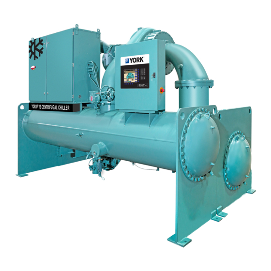
CHILLER MODEL NO. YZ
NO. OF UNITS
SYSTEM
MOTOR
VARIABLE SPEED DRIVE (VSD)
EVAPORATOR
CONDENSER
STAGE END
Supersedes: 161.01-PW2 (318)
YZ MOD A FIELD CONTROL
PURCHASER _____________________________________________
JOB NAME ________________________________________________
LOCATION ________________________________________________
ENGINEER _______________________________________________
APPROVAL
DATE ________
Issue Date:
July 18, 2018
MODIFICATIONS
CONSTRUCTION
Form: 161.01-PW2 (718)
DATE _______
Advertisement
Table of Contents

Subscribe to Our Youtube Channel
Related Manuals for York YZ


Summary of Contents for York YZ
- Page 1 Supersedes: 161.01-PW2 (318) Form: 161.01-PW2 (718) YZ MOD A FIELD CONTROL MODIFICATIONS WIRING DIAGRAMS CONTRACTOR _________________________ PURCHASER _____________________________________________ ORDER NO. ____________________________ JOB NAME ________________________________________________ JCI CONTRACT NO. _____________________ LOCATION ________________________________________________ JCI ORDER NO. _________________________ ENGINEER _______________________________________________ REFERENCE DATE ________ APPROVAL...
- Page 2 FORM 161.01-PW2 ISSUE DATE: 7/18/2018 IMPORTANT! READ BEFORE PROCEEDING! GENERAL SAFETY GUIDELINES This equipment is a relatively complicated apparatus. which it is situated, as well as severe personal injury or During rigging, installation, operation, maintenance, death to themselves and people at the site. or service, individuals may be exposed to certain com- This document is intended for use by owner-authorized ponents or conditions including, but not limited to:...
- Page 3 ASSOCIATED LITERATURE MANUAL DESCRIPTION FORM NUMBER YZ Unit Operations and Maintenance Manual 161.01-OM1 YZ Installation and Re-assembly Manual 161.01-N1 YZ Installation Checklist and Request for Startup 161.01-CL1 YZ Startup Checklist 161.01-CL2 YZ Field Connections 161.01-PW1 YZ VSD Wiring Diagrams 161.01-PW3 YZ Field Connections and Unit Wiring 161.01-PW4...
- Page 4 FORM 161.01-PW2 ISSUE DATE: 7/18/2018 SYSTEM NOMENCLATURE YZ - MA033 AN030 P042N A Product Family Special Contract Motor End Name Unit Mod Level VSD Name Stage End Name MOTOR END NAMING Bearing Family Bearing Configuration Motor Configuration Motor HP Code...
- Page 5 FORM 161.01-PW2 ISSUE DATE: 7/18/2018 EVAPORATOR NAMING F A 21 12 ─ Z 750 ─ 2 Evap Number of Passes Evap Family 1, 2, 3 Pass Evap Mod Level Evap Tube Type Evap Diameter (Inches) Evap Bundle Fill Evap Length (Feet) Evap Bundle Code Evap Pass Limit 2 , 3 Pass...
-
Page 6: Table Of Contents
FORM 161.01-PW2 ISSUE DATE: 7/18/2018 TABLE OF CONTENTS SECTION 1 - FIELD CONTROL MODIFICATIONS ....................7 Remote Mode Ready to Start Contacts ......................8 Cycling Shutdown Alarm Contacts ........................8 Safety Shutdown Alarm Contacts ........................8 Run Contacts ..............................9 Warning Alarm Contacts ........................... 9 Remote Start and Stop Contacts from Energy Management System .............. -
Page 7: Section 1 - Field Control Modifications
(see Warning on page 2). 11. Refer to YZ Field Connections and Unit Wiring (Form 161.01-PW2), for the following and re- 4. The controls specified are recommended for use,... -
Page 8: Remote Mode Ready To Start Contacts
OptiView Control Center Board not permitted to start due to a CYCLING shutdown condition. The unit will automatically restart after the cycling condition is no longer present. Refer to YZ N.O. Contacts Operations and Maintenance (Form 161.01-OM1), (in Control Center) rated for a list and explanation of all Cycling Shutdowns. -
Page 9: Run Contacts
WARNING conditions occur. Refer to all warning sor using the LOCAL start keypad button, conditions listed in YZ OptiView™ Operation (Form when the control center is in the “remote” 161.01-M2). The contacts remain closed as long as the operating mode. -
Page 10: Auxiliary Safety Shutdown
FORM 161.01-PW2 SECTION 1 - FIELD CONTROL MODIFICATIONS ISSUE DATE: 7/18/2018 AUXILIARY SAFETY SHUTDOWN MULTI-UNIT CYCLING SHUTDOWN When 115 VAC is switched to TB2-31 from a chiller For multiple chiller installation applications, Multi-Unit source at TB2-1, a safety shutdown of the chiller is Cycling Shutdown contacts are available to start and commanded. -
Page 11: Condenser Liquid Pump Run (Tb5-150/151)
Thermal-type Flow Sensor must be entered at the keypad OPERATIONS Screen using Service Access Level. Enter “J14” for Thermal- type or “TB” for Paddle-type. Refer to YZ Operations and Maintenance (Form 161.01-OM1). Condenser Flow Switch When flow is sensed, the flow sensor contacts are closed. -
Page 12: Chilled Liquid Flow Sensors
Service the Access Level. Enter “J14” for Ther- The Remote Motor Current Limit Setpoint can be re- mal-type or “TB” for Paddle-type. Refer to YZ Opera- set within the range of 100% to 30% Full Load Amps tions and Maintenance (Form 161.01-OM1). -
Page 13: Figure 14 - Remote Motor Current Limit Setpoint With 0-10Vdc
FORM 161.01-PW2 SECTION 1 - FIELD CONTROL MODIFICATIONS ISSUE DATE: 7/18/2018 For example, if the input is 5VDC, the setpoint would PWM - The Pulse Width Modulation input is in the be set to 65% as follows: form of a 1 to 11 second relay contact closure that ap- plies 115VAC to the I/O Board TB3-20 for 1 to 11 sec- SETPOINT (%) = 100 –... -
Page 14: Remote Leaving Chilled Liquid Setpoint
FORM 161.01-PW2 SECTION 1 - FIELD CONTROL MODIFICATIONS ISSUE DATE: 7/18/2018 REMOTE LEAVING CHILLED LIQUID 4-20mA - If the Remote Setpoint Min is set to 0 and the SETPOINT Max to 100 then the control signal will set the setpoint or 4-20mA 0.16mA = 1°F (If the BAS wants a 42 de- Remote Leaving Chilled Liquid Temperature Setpoint gree setpoint they should send a 6.7mA signal). -
Page 15: External Signal For Refrigeration Unit Failure
FORM 161.01-PW2 SECTION 1 - FIELD CONTROL MODIFICATIONS ISSUE DATE: 7/18/2018 • If the Remote Setpoint Min is set to 36 and the • Power failure, when the Power Restart setpoint Max to 46, then the control signal will set the on the control panel setup screen is set to manual setpoint for 1-11s 1s = 1°F above the min (If the which implies that the chiller requires Manual... -
Page 16: Optional Head Pressure Control
This is when the control panel output is at minimum, such that the flow switch requirement is maintained. Alternately, a minimum control output setpoint can be programmed for run and stop states. See the YZ Operation Manual (Form 161.01-OM1). 4-20mA 0-10VDC... -
Page 17: Section 2 - Energy Management Systems
1. Application of Sequence Control Kit: only one active when the Current Limit Control Source is unit is running, when a single unit can carry the set to Local. For more details refer to YZ Opera- cooling load. tions and Maintenance (Form 161.01-OM1). - Page 18 FORM 161.01-PW2 SECTION 2 - ENERGY MANAGEMENT SYSTEMS ISSUE DATE: 7/18/2018 6. When the Current Limit control Source is set to BAS, 0-10, 4-20 or PWM, the BAS can control the maximum allowable compressor motor AMPS from 30 to 100%, through the Remote Current Limit Setpoint.
- Page 19 FORM 161.01-PW2 ISSUE DATE: 7/18/2018 NOTES JOHNSON CONTROLS...
- Page 20 5000 Renaissance Drive, New Freedom, Pennsylvania USA 17349 800-861-1001 Subject to change without notice. Printed in USA Copyright © by Johnson Controls 2018 www.johnsoncontrols.com ALL RIGHTS RESERVED Form 161.01-PW2 (718) Issue Date: July 18, 2018 Supersedes: 161.01-PW2 (318)
Need help?
Do you have a question about the YZ and is the answer not in the manual?
Questions and answers