Table of Contents
Advertisement
Available languages
Available languages
Quick Links
IT
MANUALE DI INSTALLAZIONE USO E MANUTENZIONE
EN
INSTALLATION, USER AND MAINTENANCE MANUAL
DE
INSTALLATIONS, BEDIENUNGS UND WARTUNGSANLEITUNGEN
FR
NOTICE D'INSTALLATION
ES
MANUAL DE INSTALACIÓN, USO Y MANTENIMIENTO
ECOPALEX STAR TF
Il presente manuale è parte integrante del prodotto.
Si raccomanda di leggere attentamente le istruzioni prima
dell'installazione, manutenzione o utilizzo del prodotto.
This manual is an integral part of the product.
Read the instructions carefully before installing, servicing or
operating the product.
Die vorliegende Anleitung ist fester Bestandteil des Produkts.
Vor der Installation, Wartung und Verwendung die Anleitungen
stets aufmerksam durchlesen.
ECOPALEX STAR
Le présent manuel fait partie intégrante du produit.
Il est conseillé de lire attentivement les consignes
avant l'installation, l'entretien ou l'utilisation du produit.
Este
manual
es
parte
Se recomienda leer detenidamente las instrucciones antes
de la instalación, el mantenimiento y el uso del producto..
integrante
del
producto.
Advertisement
Table of Contents

Related Manuals for Palazzetti ECOPALEK STAR


Summary of Contents for Palazzetti ECOPALEK STAR
- Page 1 MANUALE DI INSTALLAZIONE USO E MANUTENZIONE INSTALLATION, USER AND MAINTENANCE MANUAL INSTALLATIONS, BEDIENUNGS UND WARTUNGSANLEITUNGEN NOTICE D’INSTALLATION MANUAL DE INSTALACIÓN, USO Y MANTENIMIENTO ECOPALEX STAR ECOPALEX STAR TF Le présent manuel fait partie intégrante du produit. Il presente manuale è parte integrante del prodotto. Il est conseillé...
- Page 2 Gentile cliente, desideriamo innanzitutto ringraziarLa per la preferenza che ha voluto accordarci acquistando il nostro prodotto e ci congratuliamo con Lei per la scelta. Per consentirLe di utilizzare al meglio il suo nuovo inserto a legna, la invitiamo a seguire attentamente quanto descritto nel presente manuale.
- Page 3 INDICE PREMESSA SIMBOLOGIA DESTINAZIONE D’USO SCOPO E CONTENUTO DEL MANUALE CONSERVAZIONE DEL MANUALE AGGIORNAMENTO DEL MANUALE GENERALITÀ PRINCIPALI NORME ANTINFORTUNISTICHE RISPETTATE E DA RISPETTARE GARANZIA LEGALE RESPONSABILITÀ DEL COSTRUTTORE 1.10 CARATTERISTICHE DELL’UTILIZZATORE 1.11 ASSISTENZA TECNICA 1.12 PARTI DI RICAMBIO 1.13 CONSEGNA DEL CAMINETTO AVVERTENZE PER LA SICUREZZA AVVERTENZE PER L’INSTALLATORE...
- Page 4 INDICAZIONE: Indicazioni concernenti il corretto utilizzo da PALAZZETTI carenti o inadeguate a seguito di del caminetto e le responsabilità dei preposti. eventuali modifiche, adeguamenti o applicazione di nuove ATTENZIONE: Punto nel quale viene espressa una nota tecnologie su apparecchi di nuova commercializzazione.
- Page 5 PRINCIPALI NORME ANTINFORTUNISTICHE 1.11 ASSISTENZA TECNICA RISPETTATE E DA RISPETTARE Palazzetti è in grado di risolvere qualunque problema Direttiva 2006/95/CE: “Materiale elettrico destinato ad tecnico riguardante l’impiego e la manutenzione nell’intero essere adoperato entro taluni limiti di tensione”. ciclo di vita del prodotto.
-
Page 6: Avvertenze Per La Sicurezza
AVVERTENZE PER LA SICUREZZA parte di un tecnico specializzato. • In caso d’incendio al camino cercare di spegnere AVVERTENZE PER L’INSTALLATORE il fuoco nella stufa chiudendo tutta l’aria primaria n e c e s s a r i a a l l a c o m b u s t i o n e e c h i a m a r e •... -
Page 7: Targhetta Di Identificazione
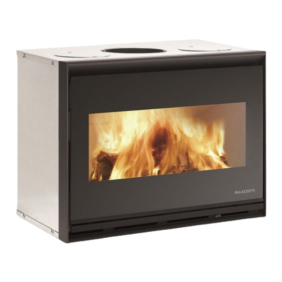
CARATTERISTICHE E MOVIMENTAZIONE E TRASPORTO DESCRIZIONE Il caminetto viene consegnato in un imballo adeguato ai lunghi trasporti. DESCRIZIONE Consigliamo di disimballare il caminetto solo quando è L’apparecchio è un caminetto da inserimento, costituito giunto sul luogo di installazione. da un monoblocco metallico dalla struttura autoportante. Il caminetto viene consegnato completo di tutte le parti È... -
Page 8: Preparazione Del Luogo Di Installazione
PREPARAZIONE DEL LUOGO DI INSTALLAZIONE SCHEMA DI MONTAGGIO (Fig. 5.1) A) Per una corretta installazione la conduttura fumi tra caminetto e canna fumaria va fatta a tenuta stagna sigillando tutti i giunti di unione. B) Presa aria esterna posteriore, garantire una distanza minima di 5 cm tra rivestimenti e tubo entrata aria comburente. - Page 9 e deve verificare che i dispositivi antinfortunistici • L ’ a p p a r e c c h i o n o n p u ò e s s e r e u t i l i z z a t o individuali e personali, siano integri e perfettamente u n a c a n n a...
-
Page 10: Operazioni Preliminari
OPERAZIONI PRELIMINARI 5.4.1 Interventi di adattamento Prima di tutto è opportuno verificare le dimensioni dello spazio disponibile nel caminetto preesistente e confrontarle con quelle dell’apparecchio e della scheda tecnica. Nel caso si renda necessario un intervento di adattamento, tagliando o modificando le pareti interne del caminetto preesistente, si ponga attenzione a non comprometterne la stabilità. -
Page 11: Circolazione Dell'aria
5.4.3 Alloggiamento kit ventilazione 680 m³/h opzionale Fig. 5.4.3a Per i caminetti esistenti predisporre un vano tecnico sotto la base dell’apparecchio per alloggiare il ventilatore, di dimensioni almeno pari a quanto indicato in figura (Fig. 5.4.3a - 5.4.3b). 5.4.4 Prese d’aria con kit di ventilazione da 680 m³/h. In aggiunta alla presa dell’aria comburente (“C”... - Page 12 CANALIZZAZIONE SU DOPPIO CONDOTTO (Fig. 5.6). Installare una bocchetta nella stanza stessa del caminetto, la seconda conduttura potrà essere utilizzata per portare l’aria calda in altre stanze della casa. CANALIZZAZIONE SU UNICO CONDOTTO Fig. 5.6 (Fig. 5.7). In alternativa collegare entrambe le mandate dell’aria calda con un tubo flessibile fino all’imboccatura degli opportuni canali di distribuzione.
- Page 13 INSERIMENTO IN UN CAMINETTO Fig. 5.10.1 Appoggiare innanzitutto l’apparecchio sul piano fuoco del caminetto. Stendere sul fondo del collare a bicchiere (posto nella parte superiore) un cordone di pasta sigilla- fuoco (sigillante che resiste a 800°C). Fare poi scorrere l’apparecchiatura nella posizione definitiva. Si può facilitarne lo scorrimento utilizzando due guide di lamiera dello spessore di 2/3 mm poste sotto l’apparecchio, che verranno tolte a posizionamento avvenuto (Fig.
-
Page 14: Prima Accensione
MESSA IN SER VIZIO ED USO APERTURA DELL’ANTA Per aprire l’anta è necessario utilizzare la mano fredda (A) in dotazione. Inserire l’attrezzo nell’apposito gancio laterale con cautela per non rischiare di danneggiare il vetro, e ruotare verso l’alto per aprire e verso il basso per chiudere. - Page 15 ACCENSIONE • Pulire il focolare dall’eventuale presenza di cenere; • aprire al massimo la regolazione dell’aria primaria (fig.6.2); • aprire la porta fuoco; • appoggiare con cautela i pezzi di legna nella camera di combustione; • posizionare un accendi-fuoco naturale sulla catasta; •...
- Page 16 6.5.2 LA COMBUSTIONE SECONDARIA Fig. 6.5.3a Si ottiene immettendo nel focolare aria preriscaldata attraverso i fori posti sulla parte superiore della parete di fondo. Entrando nel focolare I’ aria incendia il gas incombusto (monossido di carbonio) formatosi dalla combustione primaria, trasformandolo in anidride carbonica (CO2).
-
Page 17: Manutenzione E Pulizia
MANUTENZIONE E PULIZIA PRECAUZIONI DI SICUREZZA Prima di effettuare qualsiasi operazione di manutenzione o di pulizia adottare le seguenti precauzioni: A) Assicurarsi che tutte le parti del caminetto siano fredde. B) Accertarsi che le braci siano completamente spente. C) Utilizzare i dispositivi di protezione individuale previsti dalla direttiva 89/391/CEE. D) Operare sempre con attrezzature appropriate per la manutenzione. - Page 18 MANUTENZIONE DELLA CANNA FUMARIA In condizioni di normale funzionamento la pulizia del camino deve essere effettuata ogni 40 q.li di legna bruciata o almeno ogni anno salvo diverse regolamentazioni. Durante la pulizia consigliamo di togliere la scatola fumi e il Twister Flue (se presente) posti in corrispondenza dell’uscita fumi per favorire la caduta della fuliggine.
-
Page 19: Installazione
INSTALLAZIONE TWISTER FLUE DESCRIZIONE Il sistema Twister Flue è un accessorio che migliora ulteriormente le già eccezionali prestazioni della gamma Ecopalex Star. INSTALLAZIONE • Aprire la porta A, togliere in sequenza i cementi: B (parete di fondo), C (pareti laterali e D (top superiore) (Fig. 8.2.1) •... - Page 20 • Inserire il Twister Flue L nel focolare e farlo passare attraverso il foro di uscita fumi fino a mandare in battuta la flangia M con la faccia superiore del focolare facendo coincidere le scanalature N con le staffe O (Fig. 8.2.4a - Fig. 8.2.4b). •...
- Page 21 • Rimontare la scatola fumi I, il supporto e il catalizzatore (Fig. 8.2.6a - Fig. 8.2.6b). • Rimontare l’asta regolazione farfalla G e rimettere in posizione il cavetto in acciaio F avvitando la vite E (Fig. 8.2.7). • Rimontare i cementi D-C-B (Fig. 8.2.8) Fig.
- Page 22 INFORMAZIONI PER LA DEMOLIZIONE E LO SMALTIMENTO La demolizione e lo smaltimento dell’apparecchio sono ad esclusivo carico e responsabilità del proprietario. Smantellamento e smaltimento possono essere affidati anche a terzi, purché si ricorra sempre a ditte autorizzate al recupero ed all’eliminazione dei materiali in questione. Attenersi sempre e comunque alle normative in vigore nel paese dove si opera per lo smaltimento dei materiali ed eventualmente per la denuncia di smaltimento.
- Page 24 INDEX INTRODUCTION SYMBOLS DESTINATION OF USE PURPOSE AND CONTENT OF THE MANUAL PRESERVATION OF THE MANUAL UPDATE OF THIS MANUAL GENERAL INFORMATION THE MAIN ACCIDENT-PREVENTION REGULATIONS RESPECTED AND TO BE RESPECTED LEGAL WARRANTY MANUFACTURER’S RESPONSIBILITY 1.10 USER CHARACTERISTICS 1.11 TECHNICAL ASSISTANCE 1.12 SPARE PARTS 1.13...
-
Page 25: General Information
Palazzetti reserves the right to change PALAZZETTI as deficient or inadequate as a result of specifications and technical and/or functional any modifications, adaptations or the application of new characteristics of the appliance at any time technologies on newly-marketed appliances. -
Page 26: User Characteristics
Make sure that children do not approach the fireplace while it is operating with the intent of playing with it. 1.11 TECHNICAL ASSISTANCE Palazzetti is able to resolve any technical problem concerning the use and maintenance of the entire life cycle of the product. -
Page 27: Safety Warnings
SAFETY WARNINGS WARNINGS FOR THE MAINTENANCE TECHNICIAN • Observe the prescriptions contained in this manual. WARNINGS FOR THE INSTALLER • Always use personal protective equipment and other • Check that the predispositions for acceptance of means of protection. the appliance comply with the local, national and European regulations. -
Page 28: Handling And Transport
CHARACTERISTICS HANDLING AND TRANSPORT AND DESCRIPTION The fireplace is delivered in packaging suitable for long distance transportation. DESCRIPTION We recommend to unpack the fireplace only when it has The appliance is an insert fireplace, consisting of a reached the place of installation. metal monobloc with a self-supporting structure. -
Page 29: Preparing The Place Of Installation
PREPARING THE PLACE OF INSTALLATION ASSEMBLY DIAGRAM (Fig. 5.1) A) For proper installation, the smoke ducting between the fireplace and the flue must have all joints sealed. B) Rear external air intake, ensure a minimum distance of 5 cm between cladding and combustion air intake pipe. C) UNI standards require the installation of a heat recovery grille as close as possible to the ceiling. - Page 30 FLUES AND CHIMNEY COWLS The dimensioning of the chimney should be carried out in accordance with EN 13384-1. Follow the instructions given in the data sheet regarding the value of the chimney draw. The flue for the discharge of fumes must be created in compliance with the standards EN 10683, EN 1856- 1-2, EN 1857, EN 1443, EN 13384-1-3, EN 12391-1, EN15287-1 both with regard to the dimensions and to...
-
Page 31: Preliminary Operations
PRELIMINARY OPERATIONS 5.4.1 Adaptation interventions Firstly it is advisable to check the dimensions of the available space in the existing fireplace and to compare them with those of the appliance and of the technical data sheet. If an adaptation operation is necessary, by cutting or modifying the internal walls of the existing fireplace, be careful not to compromise its stability. -
Page 32: Air Circulation
5.4.4 Air intakes with 680 m³/h ventilation kit. Fig. 5.4.3a In addition to the combustion air intake (“C” - Fig. 5.4.4a) it is necessary to create the following fan air intakes: : ambient air recovery (inside the room) to the heating circuit fan, located on the side of the cladding (Ø15cm) with grille. - Page 33 PIPES ON DOUBLE DUCT (Fig. 5.6). Install a vent in the same room as the fireplace; the second pipe can be used to carry hot air to the other rooms of the house. PIPES ON A SINGLE DUCT (Fig. 5.7). Fig.
- Page 34 RECESSING IN FIREPLACES Fig. 5.10.1 First of all, place the device on the fire bed of the fireplace. Spread a line of fire-sealant paste (resistant to 800°C) on the bottom of the collar (at the top). Then move the device to its final position.
-
Page 35: Start-Up And Use
START-UP AND USE DOOR OPENING Open the door using the handle (A) supplied. Carefully insert the tool in the appropriate side seat paying attention not to damage the glass and twist it upwards to open the door and downwards to close it. The door should be opened gradually so the smoke can be drawn up the flue and not in the room. -
Page 36: Fuel Loading
IGNITION • Clean the fire box from the presence of ash; • open the primary air regulation to the maximum (fig.6.2); • open the fire door; • carefully place the pieces of wood in the combustion chamber; • place a natural fire-igniter on the pile of wood; •... - Page 37 6.5.2 SECONDARY COMBUSTION It is obtained by injecting preheated air into the fire Fig. 6.5.3a box through the holes on the upper part of the back wall. Entering the fire box the air ignites unburnt gas (carbon monoxide) formed by the primary combustion, transforming it into carbon dioxide (CO2).
-
Page 38: Maintenance And Cleaning
MAINTENANCE AND CLEANING SAFETY PRECAUTIONS Before carrying out any maintenance or cleaning operation, take the following precautions: A) Make sure that all parts of the fireplace are cold. B) Make sure that the embers are completely extinguished. C) Use personal protective equipment provided for by Directive 89/391/EEC. D) Always use appropriate equipment for maintenance. - Page 39 FLUE MAINTENANCE Under normal operating conditions, the chimney must be cleaned every 40 quintals of burnt wood or at least every year unless otherwise specified. During cleaning it is advisable to remove the flue gas box and the Twister Flue (if present) located at the smoke outlet to promote falling of the soot.
-
Page 40: Installation
TWISTER FLUE INSTALLATION DESCRIPTION The Twister Flue system is an accessory that further enhances the already outstanding performance of the Ecopalex Star range. INSTALLATION • Open the door A, remove in sequence the cements: B (base wall), C (side walls) D (upper top) (Fig. 8.2.1) •... - Page 41 • Insert the Twister Flue L into the fire box and pass it through the flue outlet hole until the flange M is in abutment with the upper face of the fire box aligning the grooves N with the brackets O (Fig. 8.2.4a - Fig. 8.2.4b). •...
- Page 42 • Refit the fume box I, the support and catalysts (Fig. 8.2.6a - Fig. 8.2.6b). • Refit the butterfly adjustment rod G and replace the steel cable F tightening the screw E (Fig. 8.2.7). • Reassemble the cements D-C-B (Fig. 8.2.8) Fig.
-
Page 43: Information For Demolition And Disposal
INFORMATION FOR DEMOLITION AND DISPOSAL The demolition and disposal of the appliance are the sole responsibility and responsibility of the owner. Decommissioning and disposal can be entrusted to a third party, provided to always use companies authorised for recovery and elimination of the materials in question. Always follow the regulations in force in the country where the appliance is working for the disposal of materials and possibly for the disposal notification. - Page 45 VERZEICHNIS VORWORT SYMBOLIK BESTIMMUNGSGEMÄSSE VERWENDUNG ZWECK UND INHALT DES HANDBUCHS AUFBEWAHRUNG DES HANDBUCHS AKTUALISIERUNG DES HANDBUCHS ALLGEMEINES GRUNDLEGENDE EINGEHALTENE UND EINZUHALTENDE UNFALLVERHÜTUNGSNORMEN GESETZLICHE GARANTIE HAFTBARKEIT DES HERSTELLERS 1.10 EIGENSCHAFTEN DES BENUTZERS 1.11 TECHNISCHER KUNDENDIENST 1.12 ERSATZTEILE 1.13 LIEFERUNG DES KAMINS SICHERHEITSHINWEISE HINWEISE FÜR DEN INSTALLATEUR HINWEISE FÜR DEN BENUTZER...
-
Page 46: Bestimmungsgemässe Verwendung
Die Verantwortung für die für die Installation des Kamins ausgeführten Arbeiten liegt nicht beim Unternehmen Inhalt PALAZZETTI, und sie liegt und bleibt beim Installateur, Dieses Handbuch enthält alle für die Installation, den der mit der Durchführung der Prüfungen bezüglich des Gebrauch und die Wartung des Kaminofens nötigen... - Page 47 GRUNDLEGENDE EINGEHALTENE 1.11 TECHNISCHER KUNDENDIENST UND EINZUHALTENDE Die Firma Palazzettiist in der Lage, jedes technische Problem UNFALLVERHÜTUNGSNORMEN bezüglich der Benutzung oder der Wartung während der Richtlinie 2006/95/EG: “Bereitstellung elektrischer gesamten Lebensdauer des Produkts zu lösen. Betriebsmittel zur Verwendung innerhalb bestimmter Der Hauptsitz steht Ihnen zur Verfügung, um Ihnen Spannungsgrenzen“.
-
Page 48: Hinweise Für Den Installateur
SICHERHEITSHINWEISE aufgrund eines nicht optimalen Rauchabzugs ist eine sorgfältige Reinigung des Schornsteins durch Fachpersonal zu veranlassen. HINWEISE FÜR DEN INSTALLATEUR • Im Falle eines Kaminbrandes versuchen, den • Sicherstellen, dass die Vorbereitungen für die Kamin durch schließen der Primärluft, die für die Kaminofeninstallation den örtlichen, nationalen und Verbrennung notwendig ist, zu schließen und europäischen Normen entsprechen. -
Page 49: Handling Und Transport
MERKMALE UND HANDLING UND TRANSPORT BESCHREIBUNG Der Kamin wird in einer Verpackung, die für lange Transporte geeignet ist, geliefert. BESCHREIBUNG Es wird empfohlen, den Kamin erst auszupacken, wenn Das Gerät ist ein Einbau-Kaminofen, bestehend aus er den Installationsort erreicht hat. einem Metallblock mit selbsttragender Struktur. -
Page 50: Vorbereitung Des Installationsorts
VORBEREITUNG DES INSTALLATIONSORTS MONTAGEPLAN (Fig. 5.1) Für eine korrekte Installation muss die Rauchgasleitung zwischen Kamin und Rauchabzugsrohr abgedichtet werden, indem man alle Anschlussstücke versiegelt. Hinterer externer Lufteinlass, einen Mindestabstand von 5 cm zwischen Verkleidungen und Rohr für die Zufuhr der Verbrennungsluft gewährleisten. Die Normen UNI sehen die Installation eines Gitters zur Wärmerückführung so nah wie möglich an der Decke vor. - Page 51 Schutzhandschuhe tragen; • Das Gerät kann nicht in einem gemeinsam genutzten Rauchabzug verwendet werden. Unfallverhütungsschuhe tragen; sicherstellen, dass der die Phasen von Montage und Demontage betreffende Bereich frei von Hindernissen ist. RAUCHABZÜGE UND SCHORNSTEINE Die Bemessung des Kamins muss gemäß EN 13384-1 erfolgen.
-
Page 52: Einleitende Massnahmen
EINLEITENDE MASSNAHMEN 5.4.1 Anpassungsarbeiten Zuerst die im bereits bestehenden Kamin vorhandenen Maße prüfen und mit denen das Gerät auf dem technischen Datenblatt vergleichen. Sollten Anpassungsarbeiten nötig sein, bei denen die Innenwände der Feuerstelle zugeschnitten oder geändert werden, darauf achten, dass die Stabilität des Kamins nicht beeinträchtigt wird. Ein eventueller Holzbalken oder jedes andere brennbare Material muss entsprechend isoliert werden (oder aus dem Strahlungsbereich der Feuerstelle entfernt werden) - Page 53 5.4.3 Installation zusätzlicher Belüftungsbausatz 680 m³/h Fig. 5.4.3a Für die bereits vorhandenen Kamine ist ein technischer Raum unter dem Sockel des Gerätes mit den in der Abbildung angegebenen Abmessungen einzurichten, in welchem der Ventilator gesetzt werden kann (Abb. 5.4.3a - 5.4.3b). 5.4.4 Lüftungklappen mit zusätzlichem Belüftungsbausatz 680 m³/h.
- Page 54 SCHACHTVERLEGUNG MIT DOPPELTER LEITUNG (Abb. 5.6). Einen Anschlussstutzen im selben Raum des Kamins installieren, die zweite Leitung kann verwendet werden, um die heiße Luft in andere Räume der Wohnung zu bringen. SCHACHTVERLEGUNG MIT EINZELLEITUNG (Abb. Fig. 5.6 5.7). Andernfalls beide Anschlüsse der Heißluft mit einem Schlauch bis zur Öffnung der entsprechenden Verteilerkanäle verbinden.
- Page 55 EINSETZEN IN EINEN KAMIN Fig. 5.10.1 Das Gerät vor allem auf die Feuerfläche des Kamins stellen. Auf den Boden der Dichtungsmanschette (im oberen Teil) einen Strang von feuerbeständigem Versiegler auftragen (beständig bis 800°C). Dann das Gerät in seine definitive Position gleiten lassen. Die Positionierung kann mit der Verwendung von zwei Blechschienen der Stärke von 2/3 mm unter dem Gerät, die man danach entfernt, erleichtert werden (Abb.
-
Page 56: Inbetriebnahme Und Gebrauch
INBETRIEBNAHME UND GEBRAUCH ÖFFNEN DER TÜR Um die Türe zu öffnen, ist es notwendig, die kalte Hand (A) aus der Ausstattung zu verwenden. Das Werkzeug in den entsprechenden seitlichen Haken vorsichtig einsetzen, um das Glas nicht zu beschädigen, und zur Öffnung nach oben und zur Schließung nach unten drehen. -
Page 57: Kontrolle Der Verbrennung
ZÜNDUNG • Den Feuerraum von eventueller Asche reinigen; • Den Regler der Primärluft vollständig öffnen (Abb. 6.2); • Die Tür des Feuerraums öffnen; • Die Holzstücke vorsichtig in die Brennkammer legen; • Einen natürlichen Feueranzünder auf die Holzscheite legen; • Kleine Holzleisten gekreuzt darauf lagen;... - Page 58 6.5.2 DIE SEKUNDÄRE VERBRENNUNG Fig. 6.5.3a erhält man durch Zufuhr von vorgeheizter Luft durch die auf dem oberen Teil des Unterbodens des Ofens befindlichen Öffnungen in die Feuerstelle. Die Luft entzündet durch ihren Eintritt in die Feuerstelle das noch unverbrannte Gas (Kohlenmonoxyd), das sich während der primären Verbrennung gebildet hat, und wandelt dieses in Kohlendioxyd (CO2) um.
-
Page 59: Wartung Und Reinigung
WARTUNG UND REINIGUNG SICHERHEITSMASSNAHMEN Vor jeglichen Wartungs- bzw. Reinigungsarbeiten müssen folgende Vorsichtsmaßnahmen ergriffen werden: A) Sicherstellen, dass alle Teile des Kamins kalt sind. B) Sicherstellen, dass die Glut vollständig gelöscht ist. C) Es muss die persönliche Schutzausrüstung, die die Richtlinie 89/391/EWG vorsieht, getragen werden. D) Immer für die Wartung geeignete Ausrüstung verwenden. - Page 60 WARTUNG DES RAUCHABZUGS Unter normalen Betriebsbedingungen muss der Schornstein alle 40 Zentner verbranntes Holz oder mindestens einmal pro Jahr gereinigt werden, sofern nichts anderes angegeben ist. Während der Reinigung empfehlen wir, den Rauchgaskasten und den Twister-Rauchabzug (falls vorhanden), die beim Rauchauslasses positioniert sind, zu entfernen, um das Herunterfallen des Rußes zu begünstigen.
-
Page 61: Installation
INSTALLATION DES TWISTER FLUE BESCHREIBUNG Das System „Twister Flue“ ist ein Zubehör, das die bereits hervorragenden Leistungen der Baureihe Ecopalex Star nocheinmal erhöht. INSTALLATION • Die Tür A öffnen und dann der Reihe nach die Betonelemente entfernen: B (Bodenplatte), C (Seitenwände) und D (Deckplatte) (Abb. - Page 62 • Den Twister Flue L in den Feuerraum einführen und durch die Rauchabzugsöffnung schieben, bis der Flansch M an der Oberseite des Ofens anliegt und die Nuten N mit den Halterungen O übereinstimmen (Abb. 8.2.4a - Abb. 8.2.4b). • Den Twister Flue im Uhrzeigersinn oder gegen den Uhrzeigersinn drehen. Wenn er losgelassen wird, müssen die Halterungen O ihm als Stütze dienen (Abb.
- Page 63 • Den Rauchgaskasten wiedermontieren, die Halterung und die Katalysatoren (Fig. 8.2.6a - Fig. 8.2.6b). • Die Regelstange des Schiebers G wiedermontieren, das Stahlkabel F wiedereinsetzen und die Schraube E wiederanschrauben (Abb. 8.2.7). • Die Betonteile D-C-B wiedermontieren (Abb. 8.2.8) Fig. 8.2.6a Ecopalex Ecopalex 66-76...
- Page 64 INFORMATIONEN ZUR DEMONTAGE UND ZUR ENTSORGUNG Die Demontage und die Entsorgung des Geräts sind Aufgabe des Eigentümers und obliegen seiner alleinigen Verantwortung. Die Demontage und die Entsorgung können auch Dritten anvertraut werden, unter der Voraussetzung, dass immer Firmen beauftragt werden, die für die Wiederverwertung und die Beseitigung der betreffenden Materialien autorisiert sind.
-
Page 66: Avertissements Pour La Sécurité
INDEX INTRODUCTION SYMBOLES DESTINATION D’USAGE OBJECTIF ET CONTENU DU MANUEL CONSERVATION DU MANUEL MISE À JOUR DU MANUEL GÉNÉRALITÉS PRINCIPALES NORMES DE PRÉVENTION DES ACCIDENTS RESPECTÉES ET À RESPECTER GARANTIE LÉGALE RESPONSABILITÉS DU FABRICANT 1.10 COMPÉTENCES DE L’UTILISATEUR 1.11 ASSISTANCE TECHNIQUE 1.12 PIÈCES DE RECHANGE 1.13... -
Page 67: Conservation Du Manuel
être considérée à la charge de la Le but du manuel est de permettre à l’utilisateur d’appliquer société PALAZZETTI ; celle-ci est, et reste, à la charge de les prescriptions prévues et de mettre en œuvre tous les l’installateur qui est tenu d’effectuer les contrôles relatifs au... -
Page 68: Garantie Légale
PRINCIPALES NORMES DE PRÉVENTION 1.11 ASSISTANCE TECHNIQUE DES ACCIDENTS RESPECTÉES ET À Palazzetti est en mesure de résoudre tout problème RESPECTER technique concernant l’utilisation et l’entretien durant Directive 2006/95/CE : « Matériel électrique destiné toute la durée de vie de l’appareil. - Page 69 AVERTISSEMENTS POUR • Si la cheminée fonctionne mal à cause d’un mauvais LA SÉCURITÉ tirage du conduit de fumée, contacter un technicien spécialisé pour le nettoyer correctement. • En cas de feu de cheminée, essayer d’éteindre MISES EN GARDE POUR L’INSTALLATEUR les flammes dans la cheminée en fermant l’arrivée •...
-
Page 70: Caractéristiques Et Description
CARACTÉRISTIQUES MANUTENTION ET TRANSPORT ET DESCRIPTION LLa cheminée est livrée dans un emballage adapté aux transports de longue durée. DESCRIPTION Nous conseillons de déballer la cheminée uniquement une L’appareil est un insert de cheminée, composé d’un monobloc fois que celle-ci se trouve sur le lieu d’installation. autoportant en métal. -
Page 71: Schéma De Montage
PRÉPARATION DU LIEU D’INSTALLATION SCHÉMA DE MONTAGE (Fig. 5.1) Pour une correcte installation, le tuyau de fumée entre la cheminée et le conduit de fumée doit être étanche avec tous les raccords bien scellés. Prise d’air extérieure arrière, garantir une distance minimale de 5 cm entre les revêtements et le tuyau d’admission de l’air comburant. - Page 72 de marche ; • Cet appareil ne peut pas être utilisé sur un conduit de fumée partagé. il doit porter des gants de protection ; il doit porter des chaussures de sécurité ; il doit s’assurer que la zone concernée par les phases de montage et de démontage est exempte de tout obstacle.
-
Page 73: Opérations Préliminaires
OPÉRATIONS PRÉLIMINAIRES 5.4.1 Interventions d’adaptation Avant tout, il faut vérifier les dimensions de l’espace disponible dans la cheminée pré-existante et les comparer avec celles de l’appareil et de la fiche technique. Si une intervention d’adaptation s’impose en coupant ou en modifiant les parois internes de la cheminée pré-existante, attention à... - Page 74 5.4.3 Emplacement du kit de ventilation 680 m³/h (en option) Fig. 5.4.3a Pour les cheminées déjà existantes il faut prévoir un compartiment technique sous la base de l’appareil pour loger le ventilateur, des dimensions indiquées en figure (Fig. 5.4.3a - 5.4.3b). 5.4.4 Prises d’air avec kit de ventilation de 680 m³/h.
- Page 75 CANALISATION SUR DOUBLE CONDUIT (Fig. 5.6). Installer une bouche dans la même pièce de la cheminée, le deuxième tuyau pourra être utilisé pour amener l’air chaud dans les autres pièces de la maison. CANALISATION SUR UN SEUL CONDUIT (Fig. Fig. 5.6 5.7).
- Page 76 INSTALLATION DANS UNE CHEMINÉE Fig. 5.10.1 Poser tout d’abord l’appareil sur le foyer de la cheminée. Étaler sur le fond du collier (placé dans la partie supérieure) de la pâte d’obturation (pâte résistante à la chaleur - 800°C). Glisser ensuite l’appareil dans son emplacement définitif.
-
Page 77: Mise En Service Et Utilisation
MISE EN SERVICE ET UTILISATION OUVERTURE DE LA PORTE Pour ouvrir la porte, utiliser la poignée (A) prévue à cet effet. Insérer l’outil dans le crochet latéral avec précaution pour ne pas risquer d’endommager la vitre et tourner vers le haut et vers le bas pour fermer. Ouvrir progressivement la porte pour permettre aux fumées du foyer d’être aspirées par le conduit de fumée en évitant ainsi de les propager dans la pièce. - Page 78 ALLUMAGE • Nettoyer le foyer de l’éventuelle présence de cendres ; • ouvrir au maximum le dispositif de réglage de l’air primaire (fig. 6.2) ; • ouvrir la porte du foyer ; • poser les bûches de bois, avec précaution, dans la chambre de combustion ; •...
- Page 79 6.5.2 LA COMBUSTION SECONDAIRE Fig. 6.5.3a Elle s’obtient en introduisant dans le foyer l’air préchauffé à travers les trous prévus sur la partie supérieure de la paroi du fond. En entrant dans le foyer l’air incendie le gaz non-brûlé (monoxyde de carbone) formé par la combustion primaire, en le transformant en anhydride carbonique (CO2).
-
Page 80: Entretien Et Nettoyage
ENTRETIEN ET NETTOYAGE CONSIGNES DE SÉCURITÉ Avant toute opération d’entretien ou de nettoyage, adopter les mesures suivantes : A) S’assurer que toutes les pièces de la cheminée sont froides. B) S’assurer que la braise est complètement éteinte. C) Utiliser les équipements de protection individuelle prévus par la Directive 89/391/CEE. D) Toujours travailler avec des outils appropriés à... - Page 81 ENTRETIEN DU CONDUIT DE FUMÉE En conditions normales de fonctionnement, le nettoyage de la cheminée doit être effectué tous les 4000 kg de bois brûlé ou au moins une fois par an sauf autre réglementation. Nous conseillons, durant le nettoyage, d’enlever le casier à fumée et le Twister Flue (si présent) placés au niveau de l’évacuation de la fumée pour faciliter la chute de suie.
- Page 82 INSTALLATION DU TWISTER FLUE DESCRIPTION Le système Twister Flue est un accessoire permettant d’améliorer ultérieurement les performances exceptionnelles de la gamme Ecopalex Star. INSTALLATION • Ouvrir la porte A, enlever les blocs dans l’ordre suivant : B (paroi du fond), C (parois latérales) et D (paroi supérieure) (Fig.
- Page 83 • Insérer le système Twister Flue L dans le foyer et le faire passer dans le trou d’évacuation de la fumée jusqu’à pousser en butée la bride M avec la face supérieure du foyer en faisant coïncider les rainures N avec les pattes O (Fig. 8.2.4a - Fig.
- Page 84 • Remonter le casier à fumée H, le support et les catalyseurs (Fig. 8.2.6a - Fig. 8.2.6b). • Remonter la tige de réglage en papillon G et remettre le câble en acier F dans la bonne position en serrant la vis E (Fig.
- Page 85 INFORMATIONS POUR LA DÉMOLITION ET LA MISE AU REBUT La démolition et la mise au rebut de l’appareil sont à la charge et sous la responsabilité du propriétaire. Le démontage et la mise au rebut peuvent aussi être confiés à des tiers à condition de toujours faire appel à...
- Page 87 ÍNDICE PREMISA SIMBOLOGÍA DESTINO DE USO FINALIDAD Y CONTENIDO DEL MANUAL CONSERVACIÓN DEL MANUAL ACTUALIZACIÓN DEL MANUAL GENERALIDAD PRINCIPALES NORMAS DE PREVENCIÓN DE ACCIDENTES QUE SE DEBEN CUMPLIR GARANTÍA LEGAL RESPONSABILIDAD DEL FABRICANTE 1.10 CARACTERÍSTICAS DEL USUARIO 1.11 ASISTENCIA TÉCNICA 1.12 PIEZAS DE REPUESTO 1.13...
-
Page 88: Actualización Del Manual
PREMISA Deterioro o pérdida En caso de necesidad solicite otra copia a PALAZZETTI. No operar si no se han comprendido bien todas las Cesión de la chimenea informaciones descritas en el manual; en caso de En caso de cesión de la chimenea, el usuario está obligado dudas siempre requerir la intervención de personal... - Page 89 PRINCIPALES NORMAS DE PREVENCIÓN 1.11 ASISTENCIA TÉCNICA DE ACCIDENTES QUE SE DEBEN CUMPLIR Palazzetti es capaz de resolver cualquier problema Directiva 2006/95/CE: “Material eléctrico destinado técnico acerca del empleo y el mantenimiento durante para ser utilizado dentro dichos límites de tensión“.
-
Page 90: Advertencias Para La Seguridad
ADVERTENCIAS PARA LA hacer que un técnico especializado la limpie SEGURIDAD cuidadosamente. • En caso de incendio de la chimenea, se debe intentar apagar el fuego en la estufa, cerrando todo el aire ADVERTENCIAS PARA EL INSTALADOR primario necesario para la combustión, y llamar •... -
Page 91: Placa De Identificación
CARACTERÍSTICAS MOVILIZACIÓN Y TRANSPORTE Y DESCRIPCIÓN La chimenea se entrega en un embalaje adecuado para transportes largos. DESCRIPCIÓN Recomendamos desembalar la chimenea sólo cuando El aparato es una chimenea de inserción, compuesta por ha llegado al lugar de instalación. un monobloque metálico con estructura autoportante. Es La chimenea se entrega con todas las partes previstas. -
Page 92: Preparación Del Lugar De Instalación
PREPARACIÓN DEL LUGAR DE INSTALACIÓN ESQUEMA DE MONTAJE (Fig. 5.1) A) Para una instalación correcta la tubería de humos entre chimenea y humero se debe realizar con estanquidad sellando todas las juntas de unión. B) Toma de aire externa posterior, garantizar una distancia mínima de 5 cm entre revestimientos y tubo de entrada aire comburente. - Page 93 no operar en condiciones adversas; actuar en perfectas condiciones psicofísicas y • El aparato no se puede utilizar en un humero comprobar que los equipos para la prevención de compartido. accidentes individuales y personales estén íntegros y funcionen debidamente; llevar los guantes para la prevención de accidentes; llevar el calzado para la prevención de accidentes;...
-
Page 94: Operaciones Preliminares
OPERACIONES PRELIMINARES 5.4.1 Operaciones de adaptación En primer lugar, es aconsejable controlar las dimensiones del espacio disponible en la chimenea existente y compararlas con las del aparato y la ficha técnica. Si es necesaria una operación de adaptación, cortando o modificando las paredes internas de la chimenea preexistente, se debe tener cuidado de no comprometer su estabilidad. -
Page 95: Circulación Del Aire
5.4.3 Alojamiento kit ventilación 680 m³/h opcional Fig. 5.4.3a Para las chimeneas existentes contemplar un compartimiento técnico debajo de la base del aparato para colocar el ventilador, con dimensiones por lo menos equivalentes a lo que se indica en la figura (Fig. 5.4.3a - 5.4.3b). 5.4.4 Toma de aire con kit de ventilación de 680 m³/h. - Page 96 CANALIZACIÓN EN DOBLE CONDUCTO (Fig. 5.6). Instalar una boca en la habitación misma de la chimenea, el segundo conducto se podrá utilizar para llevar aire caliente a otras habitaciones de la casa. CANALIZACIÓN CON UN SOLO CONDUCTO Fig. 5.6 (Fig. 5.7). Como alternativa conectar ambos envíos del aire caliente con un tubo flexible hasta la entrada de los adecuados canales de distribución.
- Page 97 INTRODUCCIÓN EN UNA CHIMENEA Fig. 5.10.1 Apoyar en primer lugar el aparato en el plano de fuego de la chimenea. Extender en el fondo del collar en forma de vaso (colocado en la parte superior) un cordón de pasta para sellar el fuego (selladora que resiste a 800°C). Luego hacer correr el aparato en la posición definitiva.
-
Page 98: Puesta En Funcionamiento Y Uso
PUESTA EN FUNCIONAMIENTO Y USO ABERTURA DE LA PUERTA Para abrir la puerta es necesario utilizar la mano fría (A) en dotación. Introducir la herramienta en el adecuado gancho lateral con precaución para no causar el daño del vidrio, y girar hacia arriba para abrir y hacia abajo para cerrar. La abertura de la puerta se debe realizar gradualmente para permitir a los humos del fogón ser aspirados por el humero evitando de esta manera salidas de humo en... -
Page 99: Control De La Combustión
ENCENDIDO • Limpiar el fogón de la eventual presencia de cenizas; • abrir al máximo la regulación del aire primario (fig.6.2); • abrir la puerta del fuego; • apoyar con precaución los trozos de leña en la cámara de combustión; •... - Page 100 6.5.2 LA COMBUSTIÓN SECUNDARIA Fig. 6.5.3a Esto se consigue introduciendo en el hogar aire precalentado a través de los orificios de la parte superior de la pared trasera. Al entrar en el hogar, el aire enciende el gas no quemado (monóxido de carbono) formado por la combustión primaria, transformándolo en dióxido de carbono (CO2).
-
Page 101: Mantenimiento Y Limpieza
MANTENIMIENTO Y LIMPIEZA PRECAUCIONES DE SEGURIDAD Antes de realizar cualquier operación de mantenimiento o de limpieza adoptar las siguientes precauciones: A) Asegurarse que todas las partes del hogar estén frías. B) Asegurarse que las brazas estén completamente apagadas. C) Utilizar los dispositivos de protección individual previstos en la directiva 89/391/CEE. D) Operar siempre con equipos adecuados para el mantenimiento. - Page 102 MANTENIMIENTO DEL HUMERO En condiciones de normal funcionamiento la limpieza de la chimenea se debe realizar cada 40 kg de leña quemada o por lo menos cada año salvo reglamentaciones distintas. Durante la limpieza se recomienda retirar la caja de humo y el Twister Flue (si está presente) colocado en la salida de humo para facilitar la caída de hollín.
-
Page 103: Instalación
INSTALACIÓN TWISTER FLUE DESCRIPCIÓN El sistema Twister Flue es un accesorio que mejora aún más los ya excepcionales rendimientos de la gama Ecopalex Star. INSTALACIÓN • Abrir la puerta A, quitar en secuencia los cementos: B (pared posterior), C (paredes laterales y D (parte superior) (Fig. 8.2.1) •... - Page 104 • Introducir el Twister Flue L en el hogar y pasarlo por el orificio de salida de humos hasta que la brida M se apoye en la cara superior del hogar, haciendo coincidir las ranuras N con los estribos O (Fig. 8.2.4a - Fig. 8.2.4b). •...
- Page 105 • Volver a montar la caja de humos H, el soporte y los catalizadores (Fig. 8.2.6a - Fig. 8.2.6b). • Volver a montar la varilla de ajuste mariposa G y poner en posición el cable de acero F apretando el tornillo E (Fig. 8.2.7). •...
- Page 106 INFORMACIONES PARA EL DESGUACE Y LA ELIMINACIÓN El desguace y la eliminación del aparato son responsabilidad exclusiva del propietario. Desguace y eliminación se pueden encargar a terceros, siempre que se recurra a empresas autorizadas en la recuperación y la eliminación de los materiales en cuestión. Cumplir siempre y de todas maneras con las normativas en vigor en el país donde se opera para la eliminación de los materiales y eventualmente para la denuncia de eliminación.
- Page 108 Palazzetti accepts no liability for any mistakes in this handbook and is free to modify the features of its products without prior notice.
Need help?
Do you have a question about the ECOPALEK STAR and is the answer not in the manual?
Questions and answers