Anritsu ShockLine MS46121A Series User Manual
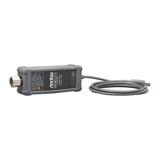
Compact vector network analyzer
Hide thumbs
Also See for ShockLine MS46121A Series:
- Programming manual (472 pages) ,
- User manual (36 pages)
Table of Contents
Advertisement
Quick Links
Advertisement
Table of Contents


Need help?
Do you have a question about the ShockLine MS46121A Series and is the answer not in the manual?
Questions and answers