Table of Contents
Advertisement
Quick Links
Maintenance Manual
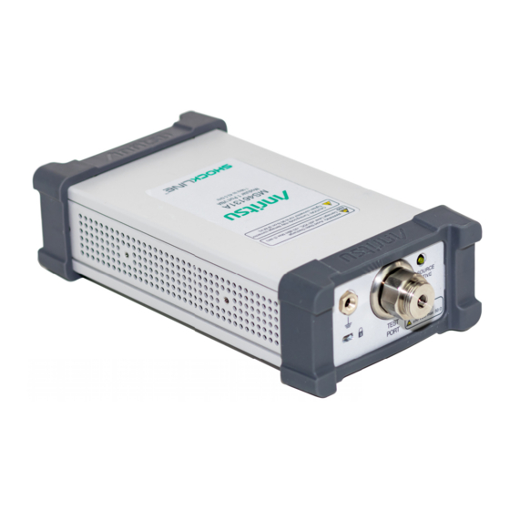
ShockLine™
Modular
Vector Network Analyzer
MS46131A-010, 1 MHz to 8 GHz
MS46131A-020, 1 MHz to 20 GHz
MS46131A-043, 1 MHz to 43.5 GHz
Anritsu Company
Part Number: 10410-00781
490 Jarvis Drive
Revision: A
Morgan Hill, CA 95037-2809
Published: January 2020
USA
Copyright 2020 Anritsu Company, USA. All Rights Reserved.
http://www.anritsu.com
Advertisement
Table of Contents
Troubleshooting

Related Manuals for Anritsu ShockLine MS46131A-010


Summary of Contents for Anritsu ShockLine MS46131A-010
- Page 1 MS46131A-010, 1 MHz to 8 GHz MS46131A-020, 1 MHz to 20 GHz MS46131A-043, 1 MHz to 43.5 GHz Anritsu Company Part Number: 10410-00781 490 Jarvis Drive Revision: A Morgan Hill, CA 95037-2809 Published: January 2020 Copyright 2020 Anritsu Company, USA. All Rights Reserved. http://www.anritsu.com...
- Page 2 Front-2 PN: 10410-00781 Rev. A MS46131A MM...
-
Page 3: Table Of Contents
Anritsu Customer Service Centers ........ - Page 4 ShockLine Application Displays ‘No Hardware Detected’ ......4-3 ShockLine Application Displays ‘Anritsu hardware is unavailable’ ....4-4 ShockLine Tray Daemon Indicator Color Definitions .
- Page 5 Table of Contents (Continued) VNA Assembly ............. 5-7 Replacement Part .
- Page 6 Contents-4 PN: 10410-00781 Rev. A MS46131A MM...
-
Page 7: Chapter 1-General Information
• MS46131A-043 Frequency Option, 1 MHz to 43.5 GHz, type K(m) test port Identification Number All Anritsu MS46131A instruments are assigned a seven-digit ID number (Serial Number), such as “1934003”. This number appears on a decal affixed to the rear panel. -
Page 8: Related Documents
Chapter 2 — Performance Verification. Repair Service In the event that the MS46131A VNA requires repair, contact your local Anritsu Service Center. See Section 1-5 “Anritsu Customer Service Centers” for contact information. When contacting Anritsu Service Center, please provide the following information: •... -
Page 9: Recommended Test Equipment
5/16 in. Open End Wrench Anritsu Model 01-201 (For Opt. 20 or 43) 8 lbf·in (0.90 N·m) Frequency: 10 MHz to 20 GHz Anritsu Model MF2412B or MF2412C P, A Frequency Counter with Option 3 Frequency: 10 MHz Symmetricom Model... - Page 10 1-6 Recommended Test Equipment General Information Table 1-1. Recommended Test Equipment for MS46131A (2 of 2) Equipment Critical Specification Recommended Manufacturer/Model Use Codes USB to GPIB National Instruments Model GPIB Adapter GPIB-USB-HS or GPIB-USB-HS+ a.P= Performance Verification; A = Adjustment PN: 10410-00781 Rev.
-
Page 11: Replaceable Parts And Assemblies
General Information 1-7 Replaceable Parts and Assemblies Replaceable Parts and Assemblies To ensure that the correct options are provided on the replacement assembly when ordering a VNA Module Assembly, all installed instrument options must be declared on the order. The installed options are listed on a label on the rear panel of the MS46131A. They can also be viewed in the ShockLine Application About box display (Select 9 Help | 1. - Page 12 1-7 Replaceable Parts and Assemblies General Information PN: 10410-00781 Rev. A MS46131A MM...
-
Page 13: Chapter 2- Performance Verification
Chapter 2 — Performance Verification Introduction to Performance Verification This chapter provides procedures to be used to verify the performance of ShockLine MS46131A. There are many levels to the concept of VNA “verification”. On the explicit VNA hardware level are operational checkout items such as port power and noise levels. On the calibrated instrument level (which includes the VNA and the calibration kit or AutoCal Automatic Calibrator) are the residual specifications (corrected directivity, source match, load match, and tracking) which are measured using traceable airlines (absolute impedance standards). -
Page 14: Second Tier Of Uncertainty Systematic Measurement Errors
2-3 Electrostatic Discharge Prevention Performance Verification Second Tier of Uncertainty Systematic Measurement Errors The second tier of uncertainty, corrected or residual uncertainty, is the result of the accuracy enhancement of VNA calibration to remove systematic errors. Systematic measurement errors are components of measurement error that in replicate measurements remains constant or values in a predictable manner. -
Page 15: Pass/Fail Determination
Performance Verification 2-5 PASS/FAIL Determination PASS/FAIL Determination Figure 2-1 shows the rule that is used to determine the pass/fail status of test results that are associated with warranted specifications. + Uncertainty Measurement Point (Reading) – Uncertainty Measurement Data Upper Specification Nominal Lower Specification... -
Page 16: System Verification Ms46131A
Anritsu Model SC8408 Offset Termination Return Loss: 20 dB (For Opt. 10) Connector: GPC-7 Calibration Tee Frequency: DC to 8 GHz Anritsu Model OSLN50A-8 or (For Opt. 10) Connector: N(m) TOSLN50A-8 Torque Wrench 3/4 in. Open End Wrench Anritsu Model 01-200 (For Opt. - Page 17 2-6 System Verification MS46131A Performance Verification 5. Allow the instrument to warm up for 60 minutes. 6. On the ShockLine Software graphic user interface (GUI), click on the Preset icon and then the OK button. a. Ensure that only S11 Log Mag is displayed on the PC monitor. 7.
- Page 18 2-6 System Verification MS46131A Performance Verification 24. Sum the magnitude values of Marker 1 and Marker 3 at the peaks (or troughs) and divide the result by two. This is the average value of the two peaks or (troughs). For example, Marker 1 = 15.9634 dB and Marker 3 = 15.641 dB, then: Average Value = (Marker 1 + Marker 3)/2 = (15.9634 dB) + (15.641 dB)/2 = 15.8022 dB 25.
- Page 19 2-6 System Verification MS46131A Performance Verification The first three columns are conversion ta- Relative to Unity Reference Return bles for return loss, reflection coefficient, Reflection X dB Loss and SWR. Ref + X Ref - X Coefficient Below Pk to Pk Ripple (dB) (dB) (dB)
-
Page 20: Instrument Key Parameter Performance Test
Equipment Required Table 2-2. Equipment Required for Frequency Accuracy Verification Equipment Critical Specification Recommended Manufacturer/Model Frequency: 10 MHz to 20 GHz Anritsu Model MF2412B or MF2412C with Frequency Counter Option 3 Frequency: 10 MHz Symmetricom Model Frequency Reference RubiSource T&M... -
Page 21: High-Level Noise
Table 2-3. Equipment Required for High-level Noise Test Equipment Critical Specification Recommended Manufacturer/Model Calibration Tee Frequency: DC to 8 GHz Anritsu Model OSLN50A-8 or (For Opt 10) Connector: N(m) TOSLN50A-8 Calibration Tee Frequency: DC to 43.5 GHz Anritsu Model TOSLKF50A-43.5... - Page 22 2-9 High-level Noise Performance Verification a. Select Sweep Setup. b. Select Freq-based Seg. Sweep Setup. c. Enter the data from the first row of Table 2-4 into the setup table on the bottom of the display of the VNA. d. Select Add. e.
- Page 23 Performance Verification 2-9 High-level Noise Table 2-4. VNA Segmented Sweep Setup for High-level Noise Test (2 of 2) # of Pts IFBW Src Pwr 8525 MHz 10000 MHz 100 Hz 10050 MHz 20000 MHz 100 Hz 20000.1 MHz 20050 MHz 100 Hz 20100 MHz 35000 MHz...
- Page 24 2-9 High-level Noise Performance Verification 2-12 PN: 10410-00781 Rev. A MS46131A MM...
-
Page 25: Chapter 3-Adjustment
Chapter 3 — Adjustment Introduction This chapter contains procedures that are used to restore and optimize the operation of the MS46131A Vector Network Analyzer. Adjustment Menu Access The hardware adjustment functions are accessed by selecting the Diagnostics button under the System menu. The Diagnostics menu is password-protected to prevent a casual VNA user from changing the correction coefficients inadvertently. - Page 26 3-2 Adjustment Menu Access Adjustment 8. The Diagnostics menu appears as shown in Figure 3-2. Figure 3-2. Diagnostics Menu 9. Click on the Hardware Cal button to access the Hardware Cal menu as shown in Figure 3-3. Figure 3-3. Hardware Cal Menu PN: 10410-00781 Rev.
-
Page 27: Time Base Adjustment
Equipment Required Table 3-1. Equipment Required for Time Base Adjustment Equipment Critical Specification Recommended Manufacturer/Model Frequency: 10 MHz to 20 GHz Anritsu Model MF2412B or MF2412C with Frequency Counter Option 3 Frequency: 10 MHz Symmetricom Model Frequency Reference RubiSource T&M... - Page 28 3-3 Time Base Adjustment Adjustment 8. Connect the DC connector from the AC/DC Adapter to the MS46131A and connect the AC power cord of AC/DC adapter to AC power source. 9. Run the ShockLine software on the external Personal Computer. 10.
-
Page 29: Factory Power Adjustment
Frequency: DC to 18 GHz Anritsu Model 34NKF50 Adapter Connector: N(m) to K(f) Interface Cable USB Type A to Micro-B Cable Anritsu Part Number 2000-1816-R Configuration: Intel Core i5-6300U Processor 4 GB RAM Personal Computer 120 GB Disk ... - Page 30 3-4 Factory Power Adjustment Adjustment 12. Press Type soft key until Offset TYPE is Fixed as shown on the display. 13. Press Value soft key. 14. Use the numeric keypad to enter 10. 15. Press Enter soft key to accept the value. 16.
-
Page 31: If Adjustment
This section provides the procedure to restore or optimize the operation of MS46131A related to the IF level in the VNA Receivers. Equipment Required • For units with N(f) test ports: • Anritsu Model OSLN50A-8 or TOSLN50A-8 Calibration Kit • For units with K(m) test ports: • Anritsu Model TOSLKF50A-43.5 Calibration Kit Procedure 1. -
Page 32: Factory Rf Calibration (Rf Cal)
User Measurement Calibration. Equipment Required • For units with N(f) test ports: • Anritsu Model OSLN50A-8 or TOSLN50A-8 Calibration Kit • For units with K(m) test ports: • Anritsu Model TOSLKF50A-43.5 Calibration Kit Procedure 1. -
Page 33: Chapter 4-Troubleshooting
Chapter 4 — Troubleshooting Introduction This chapter provides information about troubleshooting tests that can be used to check the MS46131A Vector Network Analyzer for proper operation. These tests are intended to be used as a troubleshooting tool for identifying the faulty components and checking the functionality of internal components and sub-assemblies in the MS46131A VNA. -
Page 34: Troubleshooting Test - Non-Ratio Power Level Check
MS46131A is connected to the Personal Computer running the ShockLine Software. Equipment Required • For units with N(f) test ports: • Anritsu Model TOSLN50A-8 Calibration Kit • For units with K(m) test ports: • Anritsu Model TOSLKF50A-43.5 Calibration Kit Procedure 1. -
Page 35: Troubleshooting Turn-On Problems
Windows Device Manager 2. If it is displayed as Anritsu Programmed USB with an exclaimation mark (!) on it, right-click on it and then select Uninstall. On the next dialog box, check Delete the driver software for this device and the click the OK button. -
Page 36: Shockline Application Displays 'Anritsu Hardware Is Unavailable
If an IVI client is running, ShockLine Application Software will not be able to start and the ‘Anritsu hardware is unavailable’ message will be displayed. 2. If the problem still exists, the IVI client might not be properly closed. Try manually restarting the IVI Server to release the hardware using the following steps: a. -
Page 37: Troubleshooting Operating Problems
Troubleshooting 4-5 Troubleshooting Operating Problems • Red The tray menu provides two status states when Red. • If the state is CONNECTED, an IVI Client is connected and the hardware is busy so ShockLine Application Software could not be used. •... -
Page 38: Troubleshooting Measurement Problems
4-6 Troubleshooting Measurement Problems Troubleshooting Troubleshooting Measurement Problems If the MS46131A measurement quality is suspect, the following paragraphs provide guidelines and hints for determining possible quality problems. VNA Measurement Quality The quality of MS46131A VNA measurements is determined by the following test conditions and variable: •... -
Page 39: Chapter 5-Assembly Removal And Replacement
Chapter 5 — Assembly Removal and Replacement Introduction This chapter describes the removal and replacement procedures for the various assemblies. Illustrations (drawings or photographs) in this manual may differ slightly from the instrument that you are servicing, but the basic removal and replacement functions will remain as specified. The illustrations are meant to provide assistance with identifying parts and their locations. -
Page 40: Disassembly Procedure
5-3 Disassembly Procedure Assembly Removal and Replacement Disassembly Procedure Use this procedure to prepare the MS46131A for removal and replacement procedures for all of its replaceable components. All replacement components require this common disassembly procedure. Reference Figures • Figure 5-1, “MS46131A Instrument Enclosure” on page 5-2 •... -
Page 41: Common Disassembly Procedures
Assembly Removal and Replacement 5-3 Disassembly Procedure 1 Test Port Connector Panel 2 Face Panel 3 Fan PCB Assembly 4 M3 x 6 Pan Head Phillips Screws (Qty 4) Figure 5-2. Top View of MS46131A Enclosure Common Disassembly Procedures 1. - Page 42 5-3 Disassembly Procedure Assembly Removal and Replacement Fan Side Cover Removal 6. Remove the Fan Side Cover as follows: a. Unplug the four Fan Wiring Harnesses from the Fan PCB Assembly. Refer to Figure 5-2. b. Remove the two M2.5 x 4 Flat Head Phillips screws that secure the Fan Side Cover. c.
-
Page 43: Fan Pcb Assembly
Assembly Removal and Replacement 5-4 Fan PCB Assembly Fan PCB Assembly Use this procedure to replace the Fan PCB Assembly. Replacement Parts • Fan PCB Assembly 3-ND85130 Reference Figures • Figure 5-2, “Top View of MS46131A Enclosure” on page 5-3 Replacement Procedure 1. -
Page 44: Fan Assembly
5-5 Fan Assembly Assembly Removal and Replacement Fan Assembly Use this procedure to replace the Fan Assembly. Replacement Parts • Fan Assembly 3-ND85129 Reference Figures • Figure 5-1, “MS46131A Instrument Enclosure” on page 5-2 • Figure 5-2, “Top View of MS46131A Enclosure” on page 5-3 Replacement Procedure 1. -
Page 45: Vna Assembly
Assembly Removal and Replacement 5-6 VNA Assembly VNA Assembly Use this procedure to replace the VNA Assembly. Replacement Part • VNA Assembly of MS46131A with Option 10 3-ND85131<R> • VNA Assembly of MS46131A with Option 20 3-ND85133<R> • VNA Assembly of MS46131A with Option 43 3-ND85135<R> Reference Figure •... - Page 46 5-6 VNA Assembly Assembly Removal and Replacement 16. Install the Bottom Cover. 17. Re-connect the Fan Wiring Harnesses and LED Wiring Harness from the Fan PCB Assembly. 18. Install the Top Cover. 19. Install both End Caps. PN: 10410-00781 Rev. A MS46131A MM...
-
Page 47: Test Port Adapter
Assembly Removal and Replacement 5-7 Test Port Adapter Test Port Adapter Use this procedure to replace the Test Port Adapters. Replacement Part • Test Port Adapter of MS46131A with Option 10 3-513-149 • Test Port Adapter of MS46131A with Option 20 or Option 43 3-83773 Reference Figure •... - Page 48 5-7 Test Port Adapter Assembly Removal and Replacement b. Secure the adapter to the Test Port Connector Panel with the Hex Nut and Washer supplied with the replacement adapter. c. Connect the RF Coaxial Cable Assembly from the VNA Assembly to the Test Port Adapter. d.
-
Page 49: Rf Coaxial Cable Assembly (For Instruments With Option 10)
Assembly Removal and Replacement 5-8 RF Coaxial Cable Assembly (For Instruments with Option 10) RF Coaxial Cable Assembly (For Instruments with Option 10) Use this procedure to replace the RF Coaxial Cable Assembly linking between the Test Port Adapter and the VNA Assembly of MS46131A with Option 10. - Page 50 5-8 RF Coaxial Cable Assembly (For Instruments with Option 10) Assembly Removal and Replacement 5-12 PN: 10410-00781 Rev. A MS46131A MM...
-
Page 51: Appendix A-Test Records
Appendix A — Test Records Introduction This appendix provides test record that can be used to record the performance of the ShockLine MS46131A. Make a copy of the following Test Record pages and document the measured values each time performance verification is performed. -
Page 52: Corrected Directivity
A-2 ShockLine MS46131A Test Record Test Records Instrument Information Serial Number: Firmware Revision: Operator: Options: Date: ShockLine MS46131A Test Record Corrected Directivity Table A-1. Corrected Directivity of MS46131A with Option 10 Frequency (GHz) Specification (dB) Measured (dB) Uncertainty (dB) Pass/Fail 0.001 to 6 ≥... -
Page 53: Shockline Ms46131A Instrument Key Parameter Test Record
Test Records A-3 ShockLine MS46131A Instrument Key Parameter Test Record Instrument Information Serial Number: Firmware Revision: Operator: Options: Date: ShockLine MS46131A Instrument Key Parameter Test Record Frequency Accuracy Table A-5. Frequency Accuracy Specification Frequency (See Note below) Measured Value Uncertainty Pass/Fail 1 GHz 32 Hz... - Page 54 A-3 ShockLine MS46131A Instrument Key Parameter Test Record Test Records Table A-6. High-level Noise - S11 Magnitude (2 of 2) Measurement Measured Value Uncertainty Frequency (MHz) (dB rms) Specification (dB) (dB rms) Pass/Fail 11000 0.006 0.00029 12000 0.006 0.00029 13000 0.006 0.00029 14000...
- Page 55 Test Records A-3 ShockLine MS46131A Instrument Key Parameter Test Record Table A-7. High Level Noise - S11 Phase (1 of 2) Measurement Measured Value Uncertainty Frequency (MHz) (deg rms) Specification (deg) (deg rms) Pass/Fail 0.12 0.0032 0.12 0.0032 0.12 0.0059 0.12 0.0059 0.12...
- Page 56 A-3 ShockLine MS46131A Instrument Key Parameter Test Record Test Records Table A-7. High Level Noise - S11 Phase (2 of 2) Measurement Measured Value Uncertainty Frequency (MHz) (deg rms) Specification (deg) (deg rms) Pass/Fail 31000 0.0019 32000 0.0019 33000 0.0019 34000 0.0019 35000...
-
Page 57: Index
Anritsu hardware is unavailable message ..4-4 Anritsu Service Center ..... 1-2 Client ....... .4-4 Application Cannot Launch message . - Page 58 Troubleshooting Anritsu hardware is unavailable ..4-4 Uncertainty .......2-1 Application Cannot Launch .
- Page 60 Anritsu Company 490 Jarvis Drive Anritsu utilizes recycled paper and environmentally conscious inks and toner. Morgan Hill, CA 95037-2809 http://www.anritsu.com...
Need help?
Do you have a question about the ShockLine MS46131A-010 and is the answer not in the manual?
Questions and answers