Table of Contents
Advertisement
Quick Links
Ethernet Interface
Thank you for purchasing the Mitsubishi programmable controller
MELSEC-Q Series.
Prior to use, please read both this and relevant manual thoroughly to
fully understand the product.
©1999 MITSUBISHI ELECTRIC CORPORATION
Module
User's Manual
QJ71E71-100
QJ71E71-B5
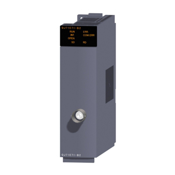
QJ71E71-B2
MODEL QJ71E71-U-HW-JE
MODEL
CODE
IB(NA)-0800009-I(1004)MEE
(Hardware)
13JQ35
Advertisement
Table of Contents

Related Manuals for Mitsubishi MELSEC QJ71E71-100


Summary of Contents for Mitsubishi MELSEC QJ71E71-100
- Page 1 Ethernet Interface Module User's Manual (Hardware) QJ71E71-100 QJ71E71-B5 QJ71E71-B2 Thank you for purchasing the Mitsubishi programmable controller MELSEC-Q Series. Prior to use, please read both this and relevant manual thoroughly to fully understand the product. MODEL QJ71E71-U-HW-JE MODEL 13JQ35 CODE IB(NA)-0800009-I(1004)MEE ©1999 MITSUBISHI ELECTRIC CORPORATION...
- Page 2 SAFETY PRECAUTIONS (Read these precautions before using this product.) Before using this product, please read this manual and the relevant manuals carefully and pay full attention to safety to handle the product correctly. Note that these precautions apply only to this product. For the safety instructions of the programmable controller system, please read the user's manual of the CPU module to use.
- Page 3 [Installation Precautions] CAUTION While pressing the installation lever located at the bottom of module, insert the module fixing tab into the fixing hole in the base unit until it stops. Then, securely mount the module with the fixing hole as a supporting point. Incorrect loading of the module can cause a malfunction, failure or drop.
- Page 4 [Wiring Instructions] CAUTION When disconnecting the communication and power cables from the module, do not pull the cables by hand. When disconnecting a cable with a connector, hold the connector to the module by hand and pull it out to remove the cable.
- Page 5 PRODUCT in one or more of the Prohibited Applications, provided that the usage of the PRODUCT is limited only for the specific applications agreed to by Mitsubishi and provided further that no special quality assurance or fail-safe, redundant or other safety features which exceed the general specifications of the PRODUCTs are required.
- Page 6 This manual confers no industrial property rights or any rights of any other kind, nor does it confer any patent licenses. Mitsubishi Electric Corporation cannot be held responsible for any problems involving industrial property rights which may occur as a result of using the contents noted in this manual.
-
Page 7: Table Of Contents
CONTENTS 1. Overview ......................1 2. Performance Specifications................1 3. Loading and Installation .................3 3.1 Handling Precautions................3 3.2 Installation Environment................3 4. Part Names ....................3 5. Connecting to the Network ................4 5.1 Connecting to the 10BASE-T/100BASE-TX ..........4 5.2 Connecting to the 10BASE5 ..............6 5.3 Connecting to the 10BASE2 ..............7 6. - Page 8 (1) For programmable controller system To configure a system meeting the requirements of the EMC and Low Voltage Directives when incorporating the Mitsubishi programmable controller (EMC and Low Voltage Directives compliant) into other machinery or equipment, refer to Chapter 9 "EMC AND LOW VOLTAGE DIRECTIVES"...
-
Page 9: Overview
1. Overview This manual describes how to install the QJ71E71-100/QJ71E71-B5/QJ71E71- B2 Ethernet interface modules (hereinafter referred to as Ethernet modules) and how to wire them with external devices. (Product Configuration) Model Item name Quantity QJ71E71-100 QJ71E71-100 Ethernet interface module QJ71E71-B5 QJ71E71-B5 Ethernet interface module QJ71E71-B2 QJ71E71-B2 Ethernet interface module... - Page 10 Specification Item QJ71E71-B5 QJ71E71-B2 10BASE5 10BASE2 Data transmission 10 Mbps (Half-duplex) speed Transmission Base band method Maximum Trans- node-to-node 2500 m (8202.10 ft.) 925 m (3034.77 ft.) mission distance specifi- Maximum segment cations 500 m (1640.42 ft.) 185 m (606.96 ft.) length Maximum number of 100 units/ segment...
-
Page 11: Loading And Installation
3. Loading and Installation 3.1 Handling Precautions (1) Do not drop or apply severe shock to the module case since it is made of resin. (2) Always make sure to touch the grounded metal to discharge the electricity charged in the body, etc., before touching the module. Failure to do so may cause a failure or malfunctions of the module. -
Page 12: Connecting To The Network
(1) LED display contents LED display Display contents: ( :Off : On) QJ71E71-100 : Normal operation ERR. : Abnormal operation INIT. COM.ERR. : Initial processing normal completion OPEN 100M INIT. : Initial processing not performed : Normally opened connection available ( 1) OPEN : Normally opened connection not available QJ71E71-B5... - Page 13 POINT During the high-speed communication (100 M bps) via 100BASE-TX connection, a communication error may occur due to the effect of high frequency noise from devices other than programmable controller in a given installation environment. The following describes countermeasures on the QJ71E71-100 side to prevent the effect of high frequency noise for construction of network system.
-
Page 14: Connecting To The 10Base5
5.2 Connecting to the 10BASE5 (1) Connecting an AUI cable <Connection procedure> ( 1) Retainer 1) Slide the retainer toward the direction B as shown in the figure. AUI cable 2) Push in the AUI cable connector all the way. 3) Slide the retainer toward the direction A as shown in the figure. -
Page 15: Connecting To The 10Base2
POINT (1) The following can be used as a countermeasure for errors due to high frequency noise according to the installation environment. Mount a ferrite core using the method shown in (2) below. Increase the retry number when communicating by TCP/IP. (2) Use the following method to mount a ferrite core when connected to the network by 10BASE5. -
Page 16: Setting From Gx Developer
6. Setting from GX Developer Using GX Developer, please make parameter setting for "Network Parameters Setting the number of Ethernet/CC IE/MELSECNET cards" ( 1) and "Ethernet Operations". Item Contents Network parameters setting the Sets "Staring I/O No.", "Network No." and "Station number of Ethernet/CC No."... -
Page 17: External Dimensions
7. External Dimensions (1) QJ71E71-100 (Units : mm (in.)) 1: When connecting the twisted pair cable, set the bending radius near the connector (reference value: R1) as four times the cable's outside diameter or larger. 2: The orientation of the connector is different (rotated) depending on the serial No. (2) QJ71E71-B5 (Units : mm (in.)) 1: When connecting the AUI cable, set the bending radius near the connector... - Page 18 (3) QJ71E71-B2 29.2 (1.15) 23.65 (0.93) 90 (3.54) (0.91) 11.5 27.4(1.08) (0.45) (Units : mm (in.)) Ethernet is a trademark of Xerox Corporation. All other company names and product names used in this manual are trademarks or registered trademarks of their respective companies.
- Page 19 MEMO...
- Page 20 Warranty Mitsubishi will not be held liable for damage caused by factors found not to be the cause of Mitsubishi; machine damage or lost profits caused by faults in the Mitsubishi products; damage, secondary damage, accident compensation caused by special factors unpredictable...
Need help?
Do you have a question about the MELSEC QJ71E71-100 and is the answer not in the manual?
Questions and answers