Table of Contents
Advertisement
Quick Links
Advertisement
Table of Contents

Subscribe to Our Youtube Channel
Related Manuals for Datalogic Gryphon GFE4400


Summary of Contents for Datalogic Gryphon GFE4400
- Page 1 Gryphon™ GFE4400 Fixed Area Imaging Bar Code Scan Engine Integration Guide...
- Page 2 Datalogic representative. Electronic versions may either be downloadable from the Datalogic web- site (www.datalogic.com) or provided on appropriate media. If you visit our website and would like to make comments or suggestions about this or other Datalogic publications, please let us know via the "Contact Datalogic"...
-
Page 3: Table Of Contents
Overview ..........................1 Unpacking the Scan Engine ................2 Scan Engine Care ....................2 Technical Support ......................3 Datalogic Website Support ................. 3 Telephone Technical Support ................3 Mounting the Scanner ................4 General Considerations ....................4 Mounting ..........................4 Mounting the Scanner Standalone .............. - Page 4 NOTES...
-
Page 5: Gryphon™ Gfe4400 Integration Guide
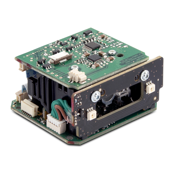
Gryphon™ GFE4400 Integration Guide This document gives instruction, mechanical details, and design consid- erations to integrate the Gryphon™ GFE4400 model (designated as “scan engine” or “OEM scan engine” in this manual) specifically into equipment-integrated scanning applications. Overview The GFE4400 OEM scan engine is a compact, decoded, omni-direc- tional imaging scan engine for fixed position OEM integration, such as price verifiers, kiosks, vending machines, point-of-sale (POS) terminals, and other equipment-integrated scanning applications. -
Page 6: Unpacking The Scan Engine
Details on the Configuration Settings and Programming are found in the GFS4400 Product Reference Guide (PRG). The Datalogic Aladdin Con- figuration Utility (available free from the Datalogic website) can also be used to modify settings. Unpacking the Scan Engine The scan engine is shipped in custom packaging. -
Page 7: Technical Support
Telephone Technical Support If you do not have internet or email access, you may contact Datalogic technical support at (541) 349-8283 or check the back cover of your manual for more contact information. -
Page 8: Mounting The Scanner
Mounting the Scanner This section describes how to design the mounting for optimum scanner performance. General Considerations A typical system uses the scanner mounted inside a host enclosure, with an opening for the scanning pattern to exit and read bar codes. The open- ing should be the size of the scanner field of view at a minimum, but only exposing as much of the scanner as necessary. -
Page 9: Mounting The Scanner Standalone
Mounting the Scanner Mounting the Scanner Standalone The OEM scanner is not intended for use in a standalone application. This model is intended to be integrated inside a host enclosure. GFS4400 models should be used when a standalone application is re- quired. - Page 10 Mounting the Scanner Table 1. J1 Connector Pins Assignment Pin Number Pin Functionality USB D+ USB D- USB Shield USB Shield EXT_TRIGGER_IN; (input to the base of a transistor, pull high to activate) RS232 TXD (output from scanner) RS232 RTS (output from scanner) RS232 RXD (input to the scanner) RS232 CTS (input to scanner) DIGITAL_OUT (open collector)
-
Page 11: Usb
Mounting the Scanner For USB setup, the recommended wiring is the following. A compatible USB cable is available from Datalogic, part number: 770111600. Figure 3. USB Cabling It is important that connections 7/8/9 be wired together for USB Auto Detection. -
Page 12: External Trigger And Digital Output
Mounting the Scanner RS-232 For RS-232 serial setup, the recommended wiring is shown below. A compatible serial cable is available from Datalogic, part number: 770111700. Figure 4. RS-232 Cabling External Trigger and Digital Output The interface allows the user's adapting interface to trigger the scan engine if not set for Automatic Reading Mode. - Page 13 Mounting the Scanner Figure 5. Connections Output Connection Vext 14Vdc max GFE44X0 USER INTERFACE 12 GND Input Trigger Using GFE44X0 Power GFE44X0 EXT TRIGGER TRIGGER 12 GND Input Trigger Using External Power GFE44X0 EXT TRIGGER Vext 5 Vdc TRIGGER 12 GND Integration Guide...
-
Page 14: User Interface
Mounting the Scanner User Interface The User Interface connection (J2) provides the integrator a means to monitor scan engine status (LEDs), and offers an additional mechanism for manually triggering the device. The user connection (J2) uses a Molex part number, 0527460671, 0.50mm (.020") Pitch FFC/FPC Connector, Right Angle, SMT, ZIF, Bottom Contact Style, 6 Circuits, Gold Contact Plating. - Page 15 Mounting the Scanner Table 2. J2 Connector Pins Pin Number Pin Functionality LED1 Ctrl Signal, Trigger (active low) LED2 Ctrl Signal, Status (open collector active low) LED3, Power, (hard wired to VCC internally) VCC_Out (5v for LED supply) Trigger Switch+ Trigger Switch- (ground) The following table outlines scan engine status assigned to each LED (with recommended colors).
-
Page 16: Good Read Beep Interface
Mounting the Scanner The following is an example of a possible connection scheme for the User Interface: Figure 7. Sample Connection Scheme Good Read Beep Interface The Beep Interface connection (J3) provides the integrator a means to tap the engine's good read beep signaling and interface with an external audio device. -
Page 17: Scanner Ventilation
Mounting the Scanner Table 3. J3 Connector Pin Assignment Pin Functionality Good Read Beep Signal (open collector, active low) Common (gnd) The Good Read Beep is a 2750Hz signal burst for 100ms provided by an on board Open Collector transistor drive circuit. Below is a simple exam- ple of an external audio implementation. -
Page 18: Integrating The Scanner To Read At The Proper Distance
Mounting the Scanner Integrating the Scanner to Read at the Proper Distance When deciding how to mount the OEM scanner, there are many criteria that must be considered. First, there are minimum and maximum distanc- es that the bar code can be from the front of the scanner to be properly read, depending on the size of the bar code. -
Page 19: Design Of The Scanner Opening
Mounting the Scanner Design of the Scanner Opening The design and placement of the scanner opening within a host enclosure are critical for optimum system performance. A typical system uses the scanner mounted inside a host enclosure, with an opening to allow the scanner Field of View to exit the scanner window and read bar codes. -
Page 20: Integrating The Scanner Behind A Window
Mounting the Scanner Integrating the Scanner Behind a Window The addition of a host enclosure window could degrade scanner performance. This is due to the optical reflective surfaces that will cause interfer- ence with the imaging technology. CAUTION It is recommended to conduct scan performance testing with any window to determine if the performance level is acceptable for the application. -
Page 21: Esd Protection
Mounting the Scanner ESD Protection The host enclosure design must provide adequate ESD protection for the scanner. Ideally, static discharge should not be allowed to discharge to the scanner. The preferred method to prevent static discharge is to pro- vide a long discharge path to all circuits. The scanner is intended to be mounted inside a host enclosure. -
Page 22: Technical Specifications
Technical Specifications Item Description Physical Characteristics Height 28.2mm (1.11") Dimensions Length 42mm (1.65") Width 48 mm (1.89") Weight (without cabling) Approximately 51.2 g (1.8 oz) Electrical Characteristics 5 VDC ± 5% Input Voltage Overvoltage tolerant to 14VDC External Trigger Input : 1V - 5V Current Consumption for 1V = 2mA max 5V = 10mA max Min Pulse Duration = 25ms *... - Page 23 Technical Specifications Item Description Digital Output : Open Collector Vout 14VDC 20 VDC max Collector Current 40 mA continuous max Vce Saturation 0.3 V max at 15 mA Power Dissipation 80 mW max at 50 °C (ambient temperature) Good Read Beep Output Output Type Open Collector Maximum Sink Current...
- Page 24 Technical Specifications Pitch Tolerance ± 40° Skew (Yaw) Tolerance ± 40° Print Contrast Minimum 25% minimum reflectance Field of View 40° H x 26° V Depth of Field (Typical) inches Code 39 5mil 16.8 Code 39 10mil 32.3 12.7 Code 39 20mil 48.3 19.0 EAN 7.5mil...
- Page 25 Code 128 ISBT; Interleaved 2 of 5 ; Standard 2 of 5; Interleaved 2 of 5 CIP (HR); Industrial 2 of 5; Discrete 2 of 5; Datalogic 2 of 5 (China Post Code/Chinese 2 of 5); IATA 2of5 Air cargo code; Code 11; Codabar; Codabar (NW7);...
-
Page 26: Rs-232 Electrical Connections
Technical Specifications User Environment Operating Temperature -4° to 122° F (-20° to 50° C) Storage Temperature -4° to 158° F (-20° to 70° C) Humidity Operating: 5% to 90% relative humidity, non condensing Ambient Light immunity Up to 100,000 Lux Regulatory (IEC-62471:2006-07) Exempt (No Risk) LED Emission Class... -
Page 27: Indicators
Technical Specifications Indicators The reader’s LED L2 of J2 illuminates to indicate various functions or er- rors. An optional “Green Spot” also performs useful functions. The fol- lowing tables list these indications. One exception to the behaviors listed in the tables is that the reader’s functions are programmable, and so may or may not be turned on. -
Page 28: Error Codes
Technical Specifications Error Codes Upon startup, if the reader’s LED2 and Green Spot are blinking alternate- ly, this means the reader has not passed its automatic Selftest and has en- tered FRU (Field Replaceable Unit) isolation mode. If the reader is reset, the sequence will be repeated. -
Page 29: Mechanical Specifications
Mechanical Specifications Physical Properties Parameter Specification 42.0mm x 48.0mm x 28.2mm Dimensions (1.65" x 1.89" x 1.11" Weight ~51.2 g (1.8 oz) Scanner Dimensions TOP VIEW Integration Guide... - Page 30 Mechanical Specifications Scanner Dimensions (continued) BOTTOM VIEW SIDE VIEW Gryphon™ GFE4400...
-
Page 31: Clearance Required For Integration
Mechanical Specifications Clearance Required for Integration TOP VIEW SIDE VIEW Integration Guide... - Page 32 Mechanical Specifications NOTES Gryphon™ GFE4400...
- Page 33 Mechanical Specifications NOTES Integration Guide...
- Page 34 Mechanical Specifications NOTES Gryphon™ GFE4400...
- Page 36 Datalogic ADC, Inc. 959 Terry Street Eugene, OR 97402 Telephone: (541) 683-5700 Fax: (541) 345-7140 June 2012 © 2012 Datalogic ADC, Inc. 820049414 (Rev. X2)
Need help?
Do you have a question about the Gryphon GFE4400 and is the answer not in the manual?
Questions and answers