Table of Contents
Advertisement
Advertisement
Table of Contents

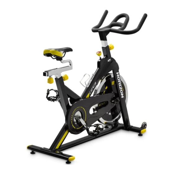
Summary of Contents for Horizon Fitness GR3
- Page 1 GR3 SERVICE MANUAL...
-
Page 2: Table Of Contents
TABLE OF CONTENTS CHAPTER 1: Serial Number Location…………………………………………3 CHAPTER 2: Indoor Cycle Operation………………………………………4 2.1 How to Move the Indoor Cycle…………………………………………4 2.2 How to Adjust the Indoor Cycle…………………………………………4 CHAPTER 3: Basic Maintenance………………………………………………7 3.1 Common Product Questions……………………………………………7 3.2 Basic Maintenance………………………………………………………7 CHAPTER 4: Troubleshooting……………………………………………………9 4.1 Bottom Bracket Noise or Damage………………………………………9 4.2 Brake Pad Noise…………………………………………………………11 4.3 Chain Lubrication………………………………………………………11... -
Page 3: Chapter 1: Serial Number Location
CHAPTER 1: Serial Number Location The serial number is located on the front stabilizer. -
Page 4: Chapter 2: Indoor Cycle Operation
CHAPTER 2: Indoor Cycle Operation 2.1 HOW TO MOVE THE INDOOR CYCLE Due to the weight of the indoor cycle, it is recommended that two people move it. While one person lifts the back of the indoor cycle, the second person firmly holds the handlebar and tips the indoor cycle forward until it rolls on the wheels. - Page 5 Handlebar adjustment Proper position for the handlebar is based primarily on comfort. Typically, the handlebar should be positioned slightly higher than the saddle for beginning cyclists. Advanced cyclists could try different heights to get the arrangement most suitable for you. ...
- Page 6 Tension control and Emergency lever The preferred level of difficulty in pedaling (resistance) can be regulated in fine increments by use of the tension control knob. To increase to resistance, turn the tension control knob clockwise. To decrease the resistance, turn the knob counter clockwise. Important: ...
-
Page 7: Chapter 3: Basic Maintenance
Our indoor cycles are some of the quietest available because they use belt drives (GR5/6) and chain drives (GR3) and cantilever brake resistance. We use the highest grade bearings and chains/belts to minimize noise. However, since the resistance system itself is so quiet, you will occasionally hear other slight mechanical noises. - Page 8 DAILY Wipe down the indoor cycle after each use to remove sweat and moisture. Use soap and water, or a diluted non-abrasive domestic cleaner solution. Rinse to remove detergent residue and then dry off. Before each session, inspect for loose components such as pedals or cranks prior to commencing the next use.
-
Page 9: Chapter 4: Troubleshooting
Chapter 4: Part Replacement 4.1 BOTTOM BRACKET NOISE OR DAMAGE Symptom: Clicking noise or damage Tools required: Combination Wrench; 15mm Socket Wrench; 6mm Allen Wrench; Slotted Screwdriver; 14mm Socket Wrench. Solution: Counter clockwise disassemble the pedals (L&R) using a combination wrench, and remove all bolts fastened outer chain guard, then take the outer chain guard (Figures 1,2) Figure 1... - Page 10 Take apart two crank caps using a Slotted Screwdriver, then remove the chain. (Figure 6, 7) Figure 6 Figure 7 Remove the crank bolt using a 14mm Socket Wrench, then remove the crank with a crank remover. (Figure 6, 7) Figure 6 Figure 7 Loosen the BB with a Socket Wrench and then take it out of the bike.
-
Page 11: Brake Pad Noise
4.2 BRAKE PAD NOISE Symptom: Squeaking noise from the brake pads Tools required: Philips screwdriver and 8mm Combination Wrench. Solution: Check to see if the brake is worn which may cause the noise. If so, replace a pair of brake pads as follows. -
Page 12: Flywheel Hub Axle Replacement
Manually and slowly rotating the flywheel and apply lubricant on chain. (Figure 18) Figure 18 Make sure the chain was lubricant evenly, then put on all removed parts in a reverse way. 4.4 FLYWHEEL HUB AXLE REPLACEMENT Symptom: Flywheel hub axle damaged or noise ... - Page 13 Loosen the flywheel’s adjusting screw using an 6mm Allen Wrench, then pull the chain out of the chain wheel. (Figure 23,24) Figure 23 Figure 24 Remove all screws fastened on the inner chain guard using a Philip Screwdriver, and adjust it uprightly as the following picture. (Figure 25, 26) Figure 25 Figure 26 Carefully move the flywheel out of the frame, and remove two nuts and two spacers...
-
Page 14: Flywheel Hub Bearing Replacement
Install a new hub axle and put the bearing on. (Figure 32, 33) Figure 32 Figure 33 Install spacer and Allen nuts. (Figure 34, 35) Please be aware that the spacer at the side of sprocket is shorter than another one. Figure 34 Figure 35 Put on all removed parts in a reverse way. - Page 15 Figure 37 Figure 38 Install the hub axle at another side of the flywheel with sprocket and put the bearing on. (Figure 39, 40) Figure 39 Figure 40 Install spacer and Allen nuts. (Figure 41, 42) Please be aware that the spacer at the side of sprocket is shorter than another one.


Need help?
Do you have a question about the GR3 and is the answer not in the manual?
Questions and answers