
Related Manuals for Kuppersbusch 640 Series


Summary of Contents for Kuppersbusch 640 Series
- Page 1 _ìáäíJáå=~ìíçã~íáÅ=ÇáëÜï~ëÜÉêë pÉêáÉë=SQM IG 6507.1E - IG 6506.0E IGS 6507.1E - IGS 6609.1E IGV 6506.1 - IGVS 6506.1 IGV 6509.1 IGV 6610.1 IGV 6508.1 - IGVS 6610.1 IGV 6509.1 - IGVS 6509.1 IGV 6609.1 - IGVS 6609.1...
- Page 2 Service Manual: H7-71-07 Repair instructions 58300000 132031 zeolite Date 15.12.2008 Repair instructions 58300000 131150 zeolite Date 15.12.2008 Repair instructions 58300000 131186 zeolite Date 15.12.2008 Repair instructions 58300000 132037 zeolite Date 15.12.2008 Responsible: Dieter Rutz KÜPPERSBUSCH HAUSGERÄTE AG Email: dieter.rutz@kueppersbusch.de Phone: (0209) 401-733 Kundendienst Fax:...
-
Page 3: Table Of Contents
GV 640 Service Manual Contents Safety ..........................7 General technical specification..................8 General features....................8 Installation and connection ................... 9 Assembly ....................... 9 Water connection ....................10 Electric connection ....................10 Disassembly ......................11 Control panel ........................ 12 Control panel ....................... 12 4.1.1 On/Off button (A).................. - Page 4 GV 640 Service Manual Door section ......................22 5.4.1 Transparent door..................22 5.4.2 Door springs .................... 22 5.4.3 Door lock ....................24 5.4.4 Door lock / child safety lock..............25 5.4.5 Installing the child safety lock..............26 Door sensor ......................26 5.5.1 Functioning of the door sensor..............
- Page 5 GV 640 Service Manual Heater pump......................53 6.7.1 Structure of the heater pump ..............53 6.7.2 Structure of the pump casing ..............53 6.7.3 Structure of the circulation pump ............53 6.7.4 Functioning of the circulation pump ............54 6.7.5 Structure of the heater ................
- Page 6 GV 640 Service Manual Water softening equipment.................. 78 8.3.1 Softening ....................78 8.3.2 Regeneration................... 78 8.3.3 Regeneration valve ................. 79 8.3.4 Flow of water in the softening equipment..........79 8.3.5 Replacing a regeneration valve............... 80 Water diverter ...................... 81 8.4.1 Checking the water diverter electrically ...........
-
Page 7: Safety
GV 640 Service Manual Safety Danger! Repairs may only be carried out by a qualified electrician! Repairs that are not carried out properly may lead to risks and injuries for the user! It is essential that you observe the following instructions in order to prevent electric shocks: •... -
Page 8: General Technical Specification
This service manual serves the purpose of providing customer service technicians who already have the know-how required to repair dishwashers with specific information on the operating mode of the GV 640 series. This manual deals with all of the appliance specifications relevant to this model. -
Page 9: Installation And Connection
GV 640 Service Manual Installation and connection Assembly In order to ensure that the lock functions perfectly and to prevent any leakages in the area of the door, the appliance must be perfectly aligned with the adjustable feet. The middle adjustable foot of integrated appliances, located at the back of the dishwasher, can be adjusted from the front. -
Page 10: Water Connection
GV 640 Service Manual Water connection If the appliance is installed onto the drain with the standard length of hose, the max. permissible height above the floor is 90 cm. If the discharge hose is extended, a max. height of 80 cm is not to be exceeded. Connection dimensions for all dishwashers 60 cm ( ) dimensions with extensions... -
Page 11: Disassembly
GV 640 Service Manual Disassembly Tools required Special tools for the ring nut on the salt box; cover of the expansion opening; exhaust air duct; water intake bolts. 1. Drain off water. • Start up any programme and close the water tap in order to empty the heat exchanger. -
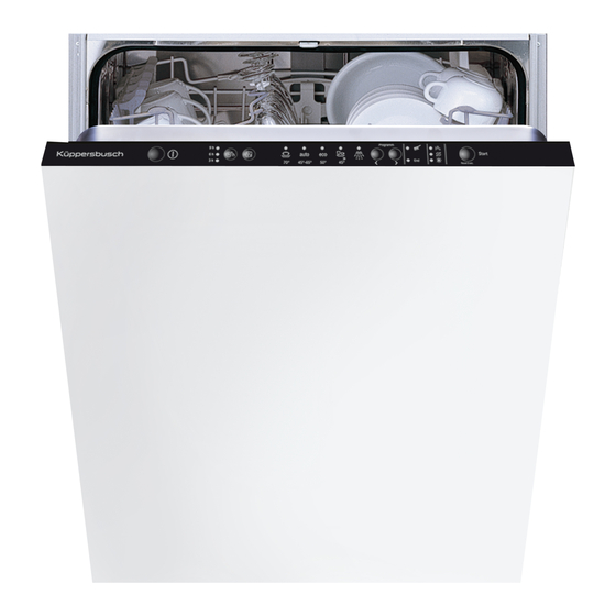
Page 12: Control Panel
GV 640 Service Manual Control panel Control panel The structure of the control panels are different; they come with a display or without. • 9 programmes operated with a rotary swich • Number of LEDs Control panel with a display Control panel without a display Control panel fully integrated, no display 4.1.1... -
Page 13: Control Module Piezo Keys
GV 640 Service Manual Control module Piezo keys Appliances with Piezo keys have a flat control panel. The stainless steel control interface reacts to even the slightest touch. This is because of a control button fitted with minute crystal elements that has been applied with glue. -
Page 14: Water Hardness
GV 640 Service Manual 4.3.2 Water hardness Keep start button B pressed. Turn the programme selection knob C until the salt refill indicator blinks. Release start button B. The current setting is shown, see chart. To change the setting turn the programme selection knob until the right setting is shown. Hardness °dH mmol/l... -
Page 15: Setting Options - Appliance Without A Display
GV 640 Service Manual Setting options - appliance without a display 4.4.1 Programme selection Close the door and switch the dishwasher on. Press button B and keep it pressed. Turn control knob C until the chosen setting range is shown in the display. Release button B. -
Page 16: Setting Options - Appliance Fully Integrated Without A Display
GV 640 Service Manual Setting options - appliance fully integrated without a display 4.5.1 Programme selection Open the door and switch the dishwasher on. Press button B and keep it pressed. Turn control knob C until the chosen setting range is shown in the display. Release button B and turn control knob C until the chosen setting is shown in the display. -
Page 17: Setting Options - Appliance With A Zeolite Drying System
GV 640 Service Manual Setting options – appliance with a zeolite drying system This will only be possible when the appliance is switched on. 4.6.1 Key layout 4.6.2 Selecting the customer settings Press key A and the “Start” key simultaneously 4.6.3 Settings •... -
Page 18: Removing The Control Panel
GV 640 Service Manual Removing the control panel This is only possible if the outer door (if present) is removed. Preparation Remove the cables on the left and right from their sockets. Remove the cable for the rinse aid refill sensor. -
Page 19: Appliance Components
GV 640 Service Manual Appliance components The dishwasher can be divided up as follows: • Modular conversion structure, in the following designs: free-standing, integratable, fully integratable. • Monobloc load-bearing base in a sound-absorbing plastic material. • Two removable side panels. •... -
Page 20: Removing
GV 640 Service Manual 5.1.2 Removing Remove the 2 screws on the front of the side panel. Fold the top of the side panel outwards. Push the side panels downwards and remove them from the retaining clips of the base pan. Outer door 5.2.1 Installation... -
Page 21: Removing
GV 640 Service Manual 5.2.2 Removing Remove the outer door from each side of the inner door by removing the 3 screws. Please note! The six panel screws at the top do not need to be removed when the outer door is taken off. Hold the outer door on the sides to prevent it from falling down. -
Page 22: Door Section
GV 640 Service Manual Door section The door section has several sub-sections. 5.4.1 Transparent door Open appliance door. Place the transparent door in the appliance and engage it in the door lock. Permanent magnet A permanent magnet will need to be placed in the inner door when the transparent door is used. - Page 23 GV 640 Service Manual Spring schedule Colour Weights of the Structural shape Height Spare-part no. marking unit doors Fully integrated 81.5 cm Black 2.5 kg to 8.5 kg Integrated 81.5 cm Blue 2.5 kg to 8.5 kg Integrated 86.5 cm Green 611339 2.5 kg to 8.5 kg...
-
Page 24: Door Lock
GV 640 Service Manual Installation Instal the cable system as for removal. Please note concerning the load cable holder! The load cable holder must be suspended exactly according to the illustration in order to prevent friction with the base pan. 1. -
Page 25: Door Lock / Child Safety Lock
GV 640 Service Manual 5.4.4 Door lock / child safety lock General view of the mechanical door lock Door lock Mechanical child safety lock (optional) Mechanical spring-loaded lock Permanent magnet The door is locked mechanically. A spring-loaded lock in the cavity frame engages in a cavity in the door frame. The mechanical child safety lock prevents the door from being opened. -
Page 26: Installing The Child Safety Lock
GV 640 Service Manual 5.4.5 Installing the child safety lock This is only possible if the worktop is removed. Door sensor The door sensor is located in the centre of the top of the inner door. Door sensor (Hall element) Door sensor screw fastenings For internal use only... -
Page 27: Functioning Of The Door Sensor
GV 640 Service Manual 5.5.1 Functioning of the door sensor Hall sensors (also Hall probes, named after Edwin Hall) use the Hall effect to measure magnetic fields. A permanent magnet is installed in the door. When the door is closed the permanent magnet is positioned right above the Hall sensor. When the door is opened or closed, the strength of the magnetic field on the Hall sensor changes. -
Page 28: Replacing The Supply Hose
GV 640 Service Manual Replacing the supply hose This is only possible if the left side panel has been removed. Removing Release the catch on the panel. Fold it away to the right. Pull out the panel. Disconnect the electrical connection. Open the clamp. -
Page 29: Replacing The Discharge Hose
GV 640 Service Manual Replacing the discharge hose This is only possible if the left side panel has been removed. Removing Release the catch on the panel. Fold out the panel. Press the discharge hose to the back out of the holder. -
Page 30: Cutlery Drawer
GV 640 Service Manual 5.8.1 Cutlery drawer The cutlery drawer is located right at the top of the rinsing cavity. It holds cutlery, other cooking utensils and espresso cups. The dishes to be washed are mainly rinsed with the ceiling centrifugal arm. See the spray system. -
Page 31: Removing The Smooth Running Top Basket Glide-Out
GV 640 Service Manual 5.8.3 Removing the smooth running top basket glide-out Disassembly Note! The holding clips may break off! Carefully bend the holding clips. It will not be possible to repair the appliance if a holding clip breaks. 1. Bend open the two holding clips with a screwdriver. -
Page 32: Bottom Basket
GV 640 Service Manual 5.8.4 Bottom basket The bottom basket is rolled out of the dishwasher on rollers. The bottom spray arm is rigid and rinses the dishes in the bottom basket (see spray system). Rounded, thickened spike tips Divided, foldable rack Holder for long-stemmed glasses Fold-down spikes Cutlery basket... -
Page 33: Appliance Functions And Components
GV 640 Service Manual Appliance functions and components Intake duct Pump cavity Zeolite container Drain valve Power module Zeolite heater additional electronic unit Heater pump Water softening equipment Fan motor Counterweight Discharge pump Heat exchanger Flow-off channel / channel Supply hose Sieve system Discharge hose For internal use only... -
Page 34: Zeolite Drying System In The Gv640
GV 640 Service Manual Zeolite drying system in the GV640 6.1.1 Zeolite container structure Container lid (stainless steel) Moulded seal Cover screen Zeolite granulate material Bottom screen (stainless steel) Tubular heating element with an air baffle Zeolite container (stainless steel) Injection duct Seal Temperature switch and fuse... -
Page 35: Zeolite Properties
GV 640 Service Manual 6.1.3 Zeolite properties Zeolite is the term for a group of minerals with a crystalline structure able to absorb (gather and retain on the surface) and to desorb (release) molecules. The name zeolite is from the Greek zeein for “boil” and lithos for “stone”. The material heats up when it absorbs hydrogen molecules. -
Page 36: Drying Phase And Adsorption
GV 640 Service Manual 6.1.5 Drying phase and adsorption The dishes are heated up at the end of the clear rinse cycle. Water evaporates from the heated surface of the dishes. Warm, moist air is now present in the interior. With the help of the fan, the moist air is sucked out of the interior and lead through the con- tainer filled with zeolite granulated material. -
Page 37: Checking The Zeolite Auxiliary Heater
GV 640 Service Manual • A reversible Klixon with a switching temperature of 190 °C is installed on the zeolite container. • The thermal fuse on the zeolite container protects the device from overheating at 230 °C in the event of a Klixon defect. If the Klixon or the thermal fuse on the zeolite container is defect, the zeolite container will need to be replaced. -
Page 38: Replacing The Fan Motor Of The Zeolite Auxiliary Heater
GV 640 Service Manual 6.1.9 Replacing the fan motor of the zeolite auxiliary heater This is only possible if the container has been folded down and the fan duct removed. Dismounting 1. Disconnect the electrical connection on the fan motor. 2. -
Page 39: 6.1.10 Replacing The Zeolite Container
GV 640 Service Manual 2. Restore the electrical connections. 6.1.10 Replacing the zeolite container This is only possible if the container has been folded down and the fan motor and the fan casing removed. Cuts on sharp edges: use protective gloves. Dismounting 1. - Page 40 GV 640 Service Manual Assembly 1. Carefully guide the zeolite container from below into the opening of the rinsing cavity. 2. Fasten the gasket. 3. Install the blow-out cap carefully and uni- formly onto the blow-out opening of the zeo- lite container and turn it clockwise until it stops and is secure.
-
Page 41: 6.1.11 Installing The Zeolite Container When The Rinsing Cavity Is Installed
GV 640 Service Manual 6.1.11 Installing the zeolite container when the rinsing cavity is installed The procedure is as follows if the blow-out cap is accidentally opened or if the zeolite container is only fastened after the cavity has been put in place: 1. - Page 42 GV 640 Service Manual 2. Remove the cap. 3. Disconnect the plug connections. For internal use only...
-
Page 43: Power Module
GV 640 Service Manual Power module Components may be electrostatic! Observe handling regulations! Connections TH401 = Water diverter TH403 = Reserve TH404 = Heat exchanger drain valve TH405 = Regeneration valve 11 K303 = heater TH402 = Filling valve 12 K301 = heater K201 = Circulation pump change-over relay K202 = Discharge pump change-over relay T412 = Dispenser coil... -
Page 44: Removing The Power Module
GV 640 Service Manual Removing the power module This is only possible if the right-hand side panel has been removed. Disconnect the mains lead from the appli- ance. Release the catches on the splash guard cover and disengage the cover to the back - top. -
Page 45: Removing The Flow-Off Channel
GV 640 Service Manual 6.5.2 Removing the flow-off channel 1. Release from the top catch. 2. Remove from the bottom guide and fold down to the side. 6.5.3 Removing the discharge hose This is only possible if the left side panel has been removed. -
Page 46: Opening The Duct For The Supply Hose
GV 640 Service Manual 6.5.5 Opening the duct for the supply hose 1. Release the catch on the panel. 2. Fold out the panel and 3. press the hose guide at a slight angle into the base pan. There is more space when the container is removed. -
Page 47: Opening Up The Rinsing Cavity
GV 640 Service Manual Opening up the rinsing cavity Please note! Close the salt box! It is essential to check that the cover of the salt box is screwed closed so that no salt solution escapes when the con- tainer is folded down! Protect the supporting surface for the rinsing cavity against scratches. -
Page 48: Mounting The Fan Motor
GV 640 Service Manual 6.6.1 Mounting the fan motor 1. Lower the housing pin with the rubber ring into the base pan. 2. Fasten it in the opening. Secure the container catches. 1. Bend the catches of the hinge plate outwards with a screwdriver. - Page 49 GV 640 Service Manual Please note! Make sure that it is properly positioned! Make sure that the weight is properly installed for floor-mounted appliances. If the heat exchanger is installed on the rinsing cavity, the joints of the hose connections must be clean.
- Page 50 GV 640 Service Manual 4. Install the supply hose. Remove the hose duct from the base pan. 1. Release the catch on the panel. 2. Fold out the panel. 5. Install the float switch safety system. 1. Press the float switch into the catch in the bottom plate.
-
Page 51: Removing The Duct
GV 640 Service Manual 6.6.3 Removing the duct Open the blow-out opening with special tools (there are two different plastic nuts!) 1. Release the catch. 2. Pull the duct slightly away from the dish- washer. 3. Remove it upwards. 6.6.4 Installing the duct 1. -
Page 52: Installing The Zeolite Auxiliary Module
GV 640 Service Manual 2. Restore the electrical connections of the Klixon. 6.6.5 Installing the zeolite auxiliary module Bring the module into its assembly position between the softening equipment and the pump cavity and fasten it with a screw. Visual inspection! You will finally need to carry out a visual inspection to make sure that no components, cables or hoses have been jammed or improperly engaged! For internal use only... -
Page 53: Heater Pump
GV 640 Service Manual Heater pump The heater pump comprises a heater, temperature sensors and a circulation pump in a casing. 6.7.1 Structure of the heater pump Pressure joint Circulation pump motor Circulation pump motor connection Heater connection Casing cover Intake socket 6.7.2 Structure of the pump casing... -
Page 54: Functioning Of The Circulation Pump
GV 640 Service Manual 6.7.4 Functioning of the circulation pump Water is drawn in through the intake socket. The guide wheel leads the water smoothly through the heating tube. The water is pumped across the pressure joint to the water diverter. The brushless DC motor (BLDC) signals different water circulation states to the power electronics unit via the power consumption of the individual windings. -
Page 55: Checking The Heater Pump
GV 640 Service Manual 6.7.7 Checking the heater pump Measuring the heater resistance The heater resistance is measured on the heater contacts of the heater pump. Readings for an intact heater: Ω Contact 2 - 3 about 10.5 Ω Contact 3 - 4 about 10.5 Ω... -
Page 56: Heating Capacity Insufficient
GV 640 Service Manual 6.7.8 Heating capacity insufficient The water is to be heated by 2.5 °C/min. If it is heated up more slowly, the water hardness and the setting of the softening equipment must be checked. It is possible that deposits have built up on the heater. Clean the dishwasher with a suitable cleaning agent and descale if necessary. -
Page 57: 6.7.10 Installing The Heater Pump
GV 640 Service Manual Carefully pull out/turn the heater pump upwards out of the hose to the water diverter. Pull the heater pump backwards, turning it slightly. 6.7.10 Installing the heater pump Please note! Moisten the rubber sealing on the inside with rinse aid. -
Page 58: Discharge Pump
GV 640 Service Manual Discharge pump Water is drawn in through the water discharge opening in the pump cavity. The impeller wheel pumps the water through the non-return valve into the discharge hose. Catch Seal Impeller wheel Cable holder The brushless DC motor (BLDC) signals different states to the power electronics unit for discharge pumping via the power consumption of the individual windings. -
Page 59: Removing The Discharge Pump
GV 640 Service Manual 6.8.2 Removing the discharge pump This is only possible if the base panel and the sheet metal have been removed - water has been drained off. 1. Pull out the plug. 2. Pull the engaging lever of the discharge pump to the front. -
Page 60: Pump Cavity
GV 640 Service Manual The new fine filter system is based on a corrugated fine filter system. When this filter is unrolled, a 1.5-fold filtering sur- face is shown. Corrugated fine sieve cylinder, rolled Fine sieve cylinder, unrolled Fine sieve cylinder, unrolled 6.10 Pump cavity This shows the pump cavity and all the attach-... -
Page 61: 6.10.1 Removing The Pump Cavity
GV 640 Service Manual 6.10.1 Removing the pump cavity Risk of injury! Cuts on sharp edges! Use protective gloves. The metal edge on the opening for the pump cavity may be sharp! Removing Preconditions: - Rinsing cavity opened up - Heater pump dismounted - Water diverter dismounted - Discharge pump dismounted - Intake pipe dismounted... -
Page 62: Functions
GV 640 Service Manual Functions This section describes the individual functions, explains the corresponding components and how they are to be installed and removed. Safety system Should functional defects in the dishwasher control system or in the structural elements occur, resulting in an over-filling of the machine, the valve combination will be closed by means of the safety system, thus blocking off the water supply. -
Page 63: Aquastop Valve
GV 640 Service Manual Removing the flow-off channel Release from the top catch. Remove from the bottom guide and fold down to the side. Base pan safety switch The safety switch is mechanically connected to the styrofoam float. Safety switch Styrofoam float Aquastop valve The aquastop valve is an electromechanical safety valve. -
Page 64: Functioning
GV 640 Service Manual 7.2.1 Functioning Leaks which occur in the region of the valve or the supply hose are led into the base pan through the leaking water hose. A styrofoam float triggers a microswitch to activate the electronic safety system. The coil of the aquastop valve is deactivated by the electronics unit and stops water from flowing into the dish- washer. -
Page 65: Float System
GV 640 Service Manual Float system A movable styrofoam disc has been let down into the base pan. Styrofoam is lighter than water, so that it floats. The styrofoam disc is mechanically connected to the safety switch. If water gets into the base pan the styrofaom disc floats to the top and activates the safety switch. -
Page 66: Dispensing Device
GV 640 Service Manual Dispensing device The cover is closed once the reservoir has been filled with rinse aid. The reservoir remains closed until it is opened again manually. The detergent dispenser is mechanically opened in the corresponding rinsing stage. Power detergent gets into the rinsing cavity. -
Page 67: Checking The Dispenser Electrically
GV 640 Service Manual When the dishwasher door is opened, the trigger mechanism will “reset”. This ensures that the deter- gent cover is opened first when the coil is next activated. If moisture remains in the detergent box and if a de- tergent tab is then put into the box, the tab will be- gin to dissolve slowly. -
Page 68: Replacing The Dispenser
GV 640 Service Manual 7.4.3 Replacing the dispenser This is only possible if the outer door or the fascia have been removed. Removing Take the cable channel out of the catches. Disconnect the plug connection. Cuts on sharp edges: Use protective gloves. Removal 2 Carefully bend the metal clamps away from the dispenser. -
Page 69: Dispensing Assistant
GV 640 Service Manual 7.4.5 Dispensing assistant The dispensing assistant is made up of interaction between the arrangement of the dispenser and the moulded handle in the top basket. The dispenser is in the middle of the door on the top surface. -
Page 70: Replacing The Aqua Sensor
GV 640 Service Manual Seal Housing Circuit board with a light barrier 7.5.1 Replacing the aqua sensor This is only possible if the base panel and the base sheet have been removed. Removing Release the catch. Turn the aqua sensor housing anti-clockwise by 90°. -
Page 71: Salt Refill Identification
GV 640 Service Manual Salt refill identification The circuit board for salt refill identification is fas- tened to the right-hand side of the softening equip- ment (front of the diswasher) with catches. Water softening equipment Circuit board with a light barrier A light barrier identifies the level of salt. -
Page 72: Status Display Lights
GV 640 Service Manual If the reservoir is empty the light beam will be re- flected in the prism. The signal received is the same as the signal transmitted. The power electronics unit will evaluate the signal received and will display it. Receiving diode Prism Transmitting diode... -
Page 73: Checking The Emotion Light
GV 640 Service Manual 7.8.3 Checking the emotion light This can only be carried out if the side panel on the right has been removed. Disconnect the plug-in connection and measure the voltage. Technical data: supply voltage of 12V 7.8.4 Replacing an emotion light This is only possible when - the worktop (optional) has been removed;... -
Page 74: Flow Sensor
GV 640 Service Manual Assembly 1. Carefully move the ribbon cable to behind the hinge plate. 2. Restore the plug connection. 3. Lock the LEDs and the Hall sensor into place in the frame of the rinsing cavity. Flow sensor 7.9.1 Functioning The flow sensor (impeller metre) is installed in the... -
Page 75: Structure Of The Mechanical Reed Contact
GV 640 Service Manual 7.9.2 Structure of the mechanical reed contact Reed contact switches activate or cut off electric circuits. They comprise contact studs melted into a glass envelope hermetically sealed with vacuum or inert gas; they form both the contact spring and the armature. -
Page 76: Water Cycle
GV 640 Service Manual Water cycle Water inlet The aquastop valve (filling valve) is opened by the electronic controls when a programme is started. Water flows into the heat exchanger through the supply hose. The flow sensor and the free flow section are located in the water channel of the heat exchanger for the intake of water. -
Page 77: Free Flow Section
GV 640 Service Manual Free flow section The free flow section is a water curve with an opening. The curved shape accelerates the water so that it flows past the opening. This ensures that virtually no water flows through the opening, even when the water pressure is low. This measure is prescibed by the “Deutsche Vereinigung des Gas- und Wasserfaches”... -
Page 78: Water Softening Equipment
GV 640 Service Manual Water softening equipment The softening equipment (ion exchanger) is a container filled with fine-grained synthetic resin granules. This synthetic resin replaces calcium and magnesium ions in the water with sodium ions on the surface. Ion exchanger Water inlet Water drain Regeneration valve... -
Page 79: Regeneration Valve
GV 640 Service Manual 8.3.3 Regeneration valve A 2-way valve (regeneration valve) is installed in the softening equipment. This valve controls the flow of water: • Direct flow into the ion exchanger • Salt box regeneration Valve with an armature Spring Coil 8.3.4... -
Page 80: Replacing A Regeneration Valve
GV 640 Service Manual When the regeneration valve is activated water flows into the salt box and accumulates salt. Water is led back to the regeneration valve through the water channels of the softening equipment. The brine flows into the ion exchanger. The granules are regenerated. The brine is led into the rinsing cavity through the heat exchanger and is drained off. -
Page 81: Water Diverter
GV 640 Service Manual Installation The installation of the valve is carried out in reverse order. Positioning the armature 1. Bring the marked points into position. 2. Press the valve with the spring into the coil again until it engages. Water diverter The water diverter controls the flow of water of the three spray levels. -
Page 82: Checking The Water Diverter Electrically
GV 640 Service Manual 8.4.1 Checking the water diverter electrically This is only possible if the side panel on the right has been removed. Measuring the water diverter motor (standard measurement) 1. Disconnect plug X2 on the power module on the leads to the water diverter motor, contact 3 and 4, measure the resistance. -
Page 83: Replacing The Water Diverter
GV 640 Service Manual 8.4.3 Replacing the water diverter This is only possible if the rinsing cavity has been folded down and the circulation pump has been dis- mounted Removing Removing the water diverter The casing of the water diverter can only be turned with force! Wear gloves. -
Page 84: Feed Pipe
GV 640 Service Manual Ceiling spray / ceiling centrifugal arm Top spray arm coupling Feed pipe Water diverter Heater pump Pump cavity Bottom spray arm Top spray arm Feed pipe The water supply to the top spray arm and the ceiling spray is brought through the inlet pipe attached to the inside of the container rear wall. -
Page 85: Heat Exchanger
GV 640 Service Manual Heat exchanger The heat exchanger is for taking in and draining off water. The illustration shows the heat exchanger compo- nents and connections. Heat exchanger Heat exchanger sealing washer 8.7.1 Replacing the sealing washer Please note! Drain off or collect the water if the washer needs to be replaced. -
Page 86: Emptying The Heat Exchanger
GV 640 Service Manual Free flow section Heat exchanger sealing washer Water drainage system on the rinsing cavity Feed from the softening equipment Water discharge to the softening equipment Water intake Feed from the discharge pump Water drainage (to the syphon) Flow sensor 10 Expansion opening 11 Discharge hose ventilation valve... -
Page 87: Expansion Opening
GV 640 Service Manual Removing Remove the two Torx screws on the exterior of the containers. Bend the protective cover of the impeller metre outwards and disconnect the plug connection. Remove the hose clamp from the water intake and pull of the supply hose. Release the catches on the front of the dishwasher. -
Page 88: Water Discharge
GV 640 Service Manual Water discharge When the discharge pump is activated so that water is drained off, the water is pumped to the heat ex- changer. The water passes through the heat exchanger to the discharge hose so that it leaves the dish- washer. -
Page 89: Non-Return Valve
GV 640 Service Manual The electronics unit identifies a higher discharge pump load and switches the pump off. An error code will be stored in the electronics unit. Water discharge inlet Water discharge outlet Air channel Float chamber Float Ventilation opening 8.11 Non-return valve The non-return valve prevents water from running back... -
Page 90: 8.11.1 Removing The Non-Return Valve
GV 640 Service Manual 8.11.1 Removing the non-return valve This is only possible if: the outer door has been removed; the base panel and the sheet metal have been removed; water has been drained out of the pump cavity; the discharge hose has been taken out of the pump cavity. -
Page 91: Error Diagnosis
GV 640 Service Manual Error diagnosis Malfunctions Error Cause Rectifying errors Check the functioning of the top spray arm (use of glass doors, spare Tab does not dissolve. Spray arm stiff, jams. part Nr. 436987 for 81 cm, 436988 for 86 cm). Tab does not drop into the basket handle of Tolerances. -
Page 92: Noises
GV 640 Service Manual Noises Error Cause Rectifying errors Noises in operation too loud. A styrofoam plate was installed on the right-hand side of some of the None. Claims concerning the occurence of noise are the same dishwashers in order to avoid transport damage. This is no longer as for dishwashers without a styrofoam plate. -
Page 93: Error Codes
GV 640 Service Manual Error codes 9.6.1 Customer settings • Calling special programs which may be present: • P0 - Error memory • P1 - Customer service program • P2 - Not relevant for customer • P3 - Not relevant for customer •... -
Page 94: Customer Settings, Selection (E.g. Piezo Electronics)
GV 640 Service Manual 9.6.2 Customer settings, selection (e.g. piezo electronics) See also the switch documents for the respective model. Activation Function Display Comment Control plan Key designation Reset Switch on the main switch Select special programs Switch off the main switch Keep keys "B"... -
Page 95: Customer Service Program - Structure
GV 640 Service Manual 9.6.3 Customer service program - structure See also the switch documents for the respective model. Can it be Function Display Time (s) Value Check measure Comment skipped? Preparation Remove approx. 0.5 ltr. of Check for tightness, regeneration valve essential if water from the salt box. -
Page 96: Error Code Chart - Structure
GV 640 Service Manual 9.6.4 Error code chart - structure See also the switch documents for the respective model. Error group In the test program At the customer Appliance behavior Results of check inside the Measures for errors appliance LEDs Display Display E:00... -
Page 97: Error Codes
GV 640 Service Manual 9.6.5 Error codes Error code Cause Rectifying errors E:00 No error. E:01 Pump activation defect. Replace the power module. E:02 Heater work relay defect. Replace the power module. E:03 Heater work relay / safety relay defect. Replace the power module. - Page 98 GV 640 Service Manual E:11 Check the leads and plug connections between the power module and the NTC error. heater; check both NTCs. E:12 No active error code. Reserved. E:13 No appliance error, only a safety measure. Appliance recognises a water temperature of > 75°C and switches the heater off. Check the water intake temperature and the connection conditions.
- Page 99 GV 640 Service Manual E:21 Circulation pump mechanically blocked. Remove the pump, check for blockage and replace if necessary. E:22 No active error code. Reserved. E:23 Check the leads and plug connections between the power module and the Incorrect discharge pump resistance readings. discharge pump;...
-
Page 100: Checking Water Hardness In The Dishwasher When Error Messages Are Displayed
GV 640 Service Manual Checking water hardness in the dishwasher when error messages are displayed Some errors require a check of the water hardness level in the dishwasher. To be clarified beforehand: • Is regenerating salt used? • Has regenerating salt been filled in? •...
Need help?
Do you have a question about the 640 Series and is the answer not in the manual?
Questions and answers