Advertisement
ATTACH YOUR RECEIPT HERE
Serial Number _____________________________ Purchase Date ______________________
Questions, problems, missing parts? Before returning to your retailer, call our customer
service department at 1-877-447-4768, 8:30 a.m. – 4:30 p.m., CST, Monday – Friday
or e-mail us at customerservice@ghpgroupinc.com.
70-10-661
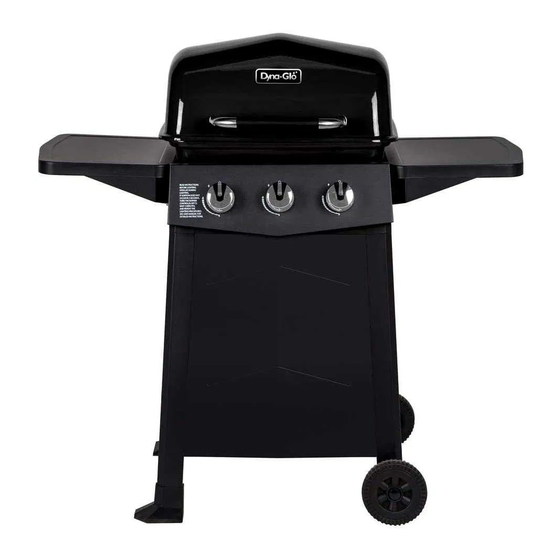
Model #DGC310CNP/DGC310CNP-D
#DGC310RNP/DGC310RNP-D
#DGC310BNP/DGC310BNP-D
#DGC310GNP/DGC310GNP-D
1
3-BURNER
LP GAS GRILL
Français p. 28
Français p.
Español p. 55
Español p.
Rev. 07/19/18
XX
XX
Advertisement

Related Manuals for Dyna-Glo DGC310CNP


Summary of Contents for Dyna-Glo DGC310CNP
- Page 1 3-BURNER LP GAS GRILL Model #DGC310CNP/DGC310CNP-D #DGC310RNP/DGC310RNP-D #DGC310BNP/DGC310BNP-D #DGC310GNP/DGC310GNP-D Français p. 28 Français p. Español p. 55 Español p. ATTACH YOUR RECEIPT HERE Serial Number _____________________________ Purchase Date ______________________ Questions, problems, missing parts? Before returning to your retailer, call our customer service department at 1-877-447-4768, 8:30 a.m.
-
Page 2: Table Of Contents
TABLE OF CONTENTS Safety Information ........................3 Package Contents ........................5 Hardware Contents ........................6 Preparation ..........................6 Assembly Instructions ........................ 7 Operation Instructions ......................... 15 Care and Maintenance ......................... 20 Troubleshooting ........................... 23 Warranty ............................25 Replacement Parts List ......................26 Assembler/Installer: This manual contains important information necessary for the proper assembly and safe use of this appliance. -
Page 3: Safety Information
SAFETY INFORMATION Please read and understand this entire manual before attempting to assemble, operate or install the product. If you have any questions regarding the product, please call customer service at: 1-877-447-4768, 8:30 a.m. – 4:30 p.m., CST, Monday – Friday. DANGER •... - Page 4 SAFETY INFORMATION WARNING • Do not place the grill under overhead combustible construction or awnings. Minimum clearance from sides and back of unit to combustible construction, 36 inches (914.4mm) from sides and back. NOTE: The installation must conform with local codes or, in the absence of local codes, with either the National Fuel Gas Code, ANSI Z223.1/NFPA 54, Natural Gas and Propane Installation Code, CSA...
-
Page 5: Package Contents
PACKAGE CONTENTS PART DESCRIPTION QUANTITY PART DESCRIPTION QUANTITY Cart Left Lower Brace Assembly Warming Rack Right Rear Leg Assembly Hood and Grill Body Assembly Right Front Leg Assembly Cooking Grate Tank Retention Bracket Heat Tent Tank Retention Support Bracket LP Gas Tank Heat Shield Cart Front Panel Side Table Assembly Cart Right Upper Brace Assembly... -
Page 6: Hardware Contents
HARDWARE CONTENTS M6x12 Wheel axle Cotter pin M4x12 M6x26 Cotter pin Wheel axle Cotter pin Wheel axle Bolt Bolt Bolt Cotter pin Wheel axle Qty. 30 Qty. 2 Qty. 2 Qty. 6 Qty. 1 M6x18 Wingnut Bolt Wingnut Qty. 1 Qty. -
Page 7: Assembly Instructions
ASSEMBLY INSTRUCTIONS Install left rear leg cap (T) onto left rear cart leg (J). Then install left front leg cap (U) onto left front cart leg(L) as illustrated. Use four M6x12 bolts (AA) to fasten the Cart Left Upper Brace Assembly (K) and Cart Left Lower Brace Assembly (M) onto Left Front Leg Assembly (L) and Left Rear Leg Assembly (J). - Page 8 ASSEMBLY INSTRUCTIONS Use four M4x12 bolts (DD) to assemble the cart front panel (R) between the Right Front Leg Assembly (O) and Left Front Leg Assembly (L). Note: The small edge of the front panel (R) should be on top. DO NOT TIGHTEN BOLTS AT THIS TIME.
- Page 9 ASSEMBLY INSTRUCTIONS Use one M6X26 bolts (EE) and one M6 wing nut (FF) to assemble the Tank Retention Bracket (P) to Tank Retention support Bracket (Q). Fasten Tank Retention Bracket (P) and Tank Retention support Bracket assembly (P+Q) in the Cart Right Upper Brace Assembly (S) Cotter pin Wheel axle by using two M6x18 bolts (GG).
- Page 10 ASSEMBLY INSTRUCTIONS With the help of a friend, place hood and grill body assembly (B) on cart assembly. Use six M6x12 bolts (AA) to fasten. Note: When performing Step7, lift grill body from front and rear panels to avoid injury to hands and fingers.
- Page 11 ASSEMBLY INSTRUCTIONS Pre-assemble two M6x12 bolts (AA) onto the upper of left brace of hood and grill body assembly (B) and do not tighten them and make sure to leave a 5mm gap between the bolt and left brace of hood and grill body. Hang one of the Side Table Assembly (F) on the bolts and fasten the Side Table Assembly (F) with two M6x12 bolts (AA).
- Page 12 Wrong Correct Wrong ASSEMBLY INSTRUCTIONS WARNING: IT IS VERY IMPORTANT TO CHECK AND ENSURE THAT EACH AND EVERY BURNER IS FULLY ENGAGED WITH THE ADJACENT VALVE ORIFICE BEFORE COMPLETING STEP 11. FAILURE TO DO SO MAY RESULT IN FIRE OR WARNING: IT IS VER IMPORT ANT TO CHECK EXPLOSION, POSSIBLY CAUSING SERIOUS...
- Page 13 ASSEMBLY INSTRUCTIONS Put one warming rack (A) in place. Slide grease cup (G) onto tracks in the bottom of firebox as illustrated.
- Page 14 ASSEMBLY INSTRUCTIONS Place gas cylinder (sold separately) upright into the notches of the tank support bracket on the bottom of right legs, orient the cylinder such that the valve opening faces the right side of the grill, and the hose is not kinked or damaged.
-
Page 15: Operation Instructions
OPERATION INSTRUCTIONS CHECKING FOR LEAKS After all connections are made, check all connections and fittings on the LP gas tank valve, gas hose and regulator for leaks with a water and soap solution. To prevent fire or explosion while testing for a leak: •... -
Page 16: Replacement Parts List
REPLACEMENT PARTS LIST... - Page 17 REPLACEMENT PARTS LIST For replacement parts, call our customer service department at 1-877-447-4768, 8:30 a.m. – 4:30 p.m., CST, Monday – Friday. PART DESCRIPTION PART# Hood Black 70-01-663 / Blue 70-01-757 / Red 70-01-758 / Green 70-01-759 Badge 70-10-540 Lid Handle Heat Shield Assembly 70-01-664 Lid Bumper 70-01-665...
Need help?
Do you have a question about the DGC310CNP and is the answer not in the manual?
Questions and answers