Table of Contents
Advertisement
ANS Z21.58b- 2012
CSA 1.6b- 2012
Outdoor Cooking
Gas Appliances
ATTACH YOUR RECEIPT HERE
Serial Number _____________________________ Purchase Date ______________________
Questions, problems, missing parts? Before returning to your retailer, call our customer
service department at 1-877-447-4768, 8:30 a.m. – 4:30 p.m., CST, Monday – Friday
or e-mail us at customerservice@ghpgroupinc.com.
70-10-537
.
WITH SIDE BURNER
1
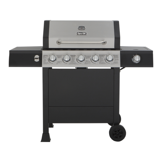
5-BURNER
LP GAS GRILL
Model #DGF510SBP
Rev. 8/13/15
Advertisement
Table of Contents

Related Manuals for Dyna-Glo DGF510SBP


Summary of Contents for Dyna-Glo DGF510SBP
- Page 1 5-BURNER LP GAS GRILL WITH SIDE BURNER Model #DGF510SBP ANS Z21.58b- 2012 CSA 1.6b- 2012 Outdoor Cooking Gas Appliances ATTACH YOUR RECEIPT HERE Serial Number _____________________________ Purchase Date ______________________ Questions, problems, missing parts? Before returning to your retailer, call our customer service department at 1-877-447-4768, 8:30 a.m.
-
Page 2: Table Of Contents
TABLE OF CONTENTS Safety Information ........................3 Package Contents ........................5 Hardware Contents ........................6 Preparation ..........................6 Assembly Instructions ........................ 7 Operation Instructions ......................... 17 Care and Maintenance ......................... 22 Troubleshooting ........................... 25 Warranty ............................27 Replacement Parts List ......................28 Assembler/Installer: This manual contains important information necessary for the proper assembly and safe use of this appliance. -
Page 3: Safety Information
SAFETY INFORMATION Please read and understand this entire manual before attempting to assemble, operate or install the product. If you have any questions regarding the product, please call customer service at: 1-877-447-4768, 8:30 a.m. – 4:30 p.m., CST, Monday – Friday. DANGER •... - Page 4 SAFETY INFORMATION WARNING • Do not place the grill under overhead combustible construction or awnings. Minimum clearance from sides and back of unit to combustible construction, 36in 36in 914.4mm 36 inches (914.4mm) from sides and 914.4mm back. NOTE: The installation must conform with local codes or, in the absence of local codes, with either the National Fuel Gas Code, ANSI Z223.1/NFPA 54, Natural...
-
Page 5: Package Contents
PACKAGE CONTENTS PART DESCRIPTION QUANTITY PART DESCRIPTION QUANTITY Left Leg Assembly Hood Handle Leg End Cap Temp Gauge Cylinder Block Bar Grill Body Assembly Cart Rear Support Control Knob Bottom Shelf’s Rear Grease Pan Bracket Assembly Grease Cup Cart Front Panel - Upper Warming Rack Cart Front Panel - Lower Cooking Grate... -
Page 6: Hardware Contents
HARDWARE CONTENTS M5x12 M6x16 ST4.8x10 M10-M6 Bolt Wingnut Bolt Screw Wrench Qty. 2 Qty. 2 Qty. 2 Qty. 2 Qty. 2 Qty. 34 M4x10 Washer Bolt Spring Washer Qty. 2 Qty. 2 Qty. 2 PREPARATION Before beginning assembly of product, make sure all parts are present. Compare parts with package contents list on previous page and hardware contents above. -
Page 7: Assembly Instructions
ASSEMBLY INSTRUCTIONS Put two leg end caps (P) under left leg assembly (O), and fasten them with two ST4.8X10 screws (AA). Hardware Used ST4.8x10 Screw Slide the axle (X) through the right leg assembly (V) and then put the wheels (Y) on both sides, and tighten the wheels with M10 nuts (BB) with wrenches (CC). - Page 8 ASSEMBLY INSTRUCTIONS Use eight M6x16 bolts (DD) to assemble cart front panel - upper (T) and cart front panel - lower (U) between left leg assembly (O) and right leg assembly (V). Please note the front panel - lower’s (U) direction, the side with rivet nut in the middle should be downward.
- Page 9 ASSEMBLY INSTRUCTIONS Assemble bottom shelf assembly to the left leg assembly (O) and right leg assembly (V) with four M6X16 bolts (DD). Hardware Used M6x16 Bolt Bottom Shelf Assembly Use four M6x16 bolts (DD) to fasten the cart rear support (R) to the left and right leg assembly.
- Page 10 ASSEMBLY INSTRUCTIONS Assemble the hood handle (A) to the hood with two wingnuts (FF) and two spring washers (GG) and two M6 washers (HH). Hardware Used M6 Wingnut M6 Spring Washer M6 Washer Assemble the temp gauge (B) onto the hood. Please use the washer and wing nut pre-assembled with temp gauge to install the temp gauge (B) onto the hood.
- Page 11 ASSEMBLY INSTRUCTIONS Assemble the grill body assembly (C) onto the cart assembly with four M6x16 bolts (DD). Hardware Used M6x16 Bolt Pre-assemble two M6x16 bolts (DD) onto the grill body assembly (C) and do not tighten them and make sure to leave a 5mm gap between the bolt and grill body’s end cap.
- Page 12 ASSEMBLY INSTRUCTIONS Pre-assemble two M6x16 bolts (DD) onto the grill body assembly (C) and do not tighten them and make sure to leave a 5mm gap between the bolt and grill body’s end cap. Then hang the right side burner body (M) on the bolts and fasten the right side burner body (M) with three M6x16 bolts (DD) and tighten all bolts.
- Page 13 ASSEMBLY INSTRUCTIONS Disassemble two M4x10 bolts that are pre- assembled on the side burner (L) and use them to assemble the side burner (L) on the right side burner body (M). Please ensure the gas valve orifice is correctly positioned inside side burner inlet (venturi). Correct Incorrect Incorrect...
- Page 14 ASSEMBLY INSTRUCTIONS Put the side burner rack (K) in place. Assemble the six control knobs (D).
- Page 15 ASSEMBLY INSTRUCTIONS Put the five heat tents (I) into place over each burner. Put three cooking grates (H) and one warming rack (G) in place.
- Page 16 ASSEMBLY INSTRUCTIONS Place grease pan (E) and grease cup (F) in place. Place gas cylinder (sold separately) into the nesting hole located in the Bottom shelf (W). Rotate the gas cylinder until the hose/regulator coupling aligns with the threaded valve of the cylinder.
-
Page 17: Operation Instructions
OPERATION INSTRUCTIONS CHECKING FOR LEAKS After all connections are made, check all connections and fittings on the LP gas tank valve, gas hose and regulator for leaks with a water and soap solution. To prevent fire or explosion while testing for a leak: •... - Page 18 OPERATION INSTRUCTIONS CONNECTING GAS CYLINDER The propane gas supply cylinder to be used must be constructed and marked in accordance with the Specifications for LP Gas Cylinders of the U.S. Department of Transportation (D.O.T.) or the National Standard of Canada, CAN/CSA-B339, Cylinders, Spheres and Tubes for Transportation of Dangerous Goods;...
- Page 19 OPERATION INSTRUCTIONS NOTE: Other cylinders may be acceptable for use with this appliance provided they are compatible with the appliance nesting hole and retention means. Refer to Step 20 of the Assembly Instructions for correct cylinder to cylinder holder connection. WARNING ALL INSTRUCTIONS AND SAFEGUARDS ON THIS PAGE MUST BE FOLLOWED TO PREVENT FIRE, DAMAGE AND/OR INJURY.
- Page 20 OPERATION INSTRUCTIONS Lighting The Grill Before first use: Remove all hangings or plastic straps, if present. Before you cook on your new gas grill, it is important to clean your grill with heat. To do this, operate the grill for approximately 15 minutes with the lid closed and the control knob in the highest position.
- Page 21 OPERATION INSTRUCTIONS LIGHTING THE GRILL WITH A MATCH 1. Open the lid. 2. Insert a match in the end of the match holder that is installed on the right leg assembly. 3. Light the match. 4. Immediately place the lit match through the spaces in the grill gates near the ports of the burner between the heat tents as shown.
-
Page 22: Care And Maintenance
CARE AND MAINTENANCE Cooking Grates The best time to ‘burn-off’ the cooking grates is after every use (approx. 15 minutes). The grill is already hot from cooking thus requiring less fuel to obtain necessary temperature for ‘burn-off’. To ‘burn off’ or heat clean your grill, turn the burners to highest position and run for 15 minutes with the lid closed. - Page 23 CARE AND MAINTENANCE Burner Assembly Warming Rack Removing The Burner Assembly Cooking Grates 1. Make sure all control knobs are in the OFF Heat Tents position, gas supply valve is closed, and the gas hose is disconnected from the gas supply. 2.
- Page 24 CARE AND MAINTENANCE Cleaning the Burner Assembly – Make sure the grill is cool 1.Turn gas off at the control knobs and LP gas cylinder. 2.Disconnect LP gas cylinder from regulator and hose. 3.Remove warming rack, cooking grates and heat tents. 4.Detach burner by removing the cotter pins at the back of the burners to detach them from the brackets.
-
Page 25: Troubleshooting
TROUBLESHOOTING If you have any questions regarding the product, please call customer service at 1-877-447-4768, 8:30 a.m. – 4:30 p.m., CST, Monday – Friday. PROBLEM POSSIBLE CAUSE CORRECTIVE ACTION The burner will not 1. The igniter electrode may be 1. Clean the ignitor electrode. light using the covered with grease or residue. - Page 26 TROUBLESHOOTING PROBLEM POSSIBLE CAUSE CORRECTIVE ACTION The burner will not 1. Match not reaching burners 1. Use match holder found in light with a match. (when holding match with cabinet door. hand). 2. Check fuel level and refill tank if 2.
-
Page 27: Warranty
GHP Group Inc. 6440 W. Howard Street Niles, Il, USA 60714-3302 Item Name: 5-Burner LP Gas Grill With Side Burner Model #: DGF510SBP Main Burner Total rated BTU: 60,000 BTU/Hr Side Burner rated BTU: 12,000 BTU/Hr... -
Page 28: Replacement Parts List
REPLACEMENT PARTS LIST... - Page 29 REPLACEMENT PARTS LIST For replacement parts, call our customer service department at 1-877-447-4768, 8:30 a.m. – 4:30 p.m., CST, Monday – Friday. PART DESCRIPTION PART # Temp gauge assembly 70 - 04 -100 Badge 70 - 10 -540 Hood handle 70 - 01 -173 Warming rack 70 - 01 -292...
- Page 30 REPLACEMENT PARTS LIST For replacement parts, call our customer service department at 1-877-447-4768, 8:30 a.m. – 4:30 p.m., CST, Monday – Friday. PART DESCRIPTION PART # Hardware pack 70 - 09 - 121 Instruction manual 70 - 10 - 537 Printed in China 70-10-537...
Need help?
Do you have a question about the DGF510SBP and is the answer not in the manual?
Questions and answers