Table of Contents
Advertisement
Available languages
Available languages
ANS Z21.58b- 2012
CSA 1.6b- 2012
Outdoor Cooking
Gas Appliances
ATTACH YOUR RECEIPT HERE
Serial Number _____________________________ Purchase Date ______________________
Questions, problems, missing parts? Before returning to your retailer, call our customer
service department at 1-877-447-4768, 8:30 a.m. – 4:30 p.m., CST, Monday – Friday
or e-mail us at customerservice@ghpgroupinc.com.
70-10-121
.
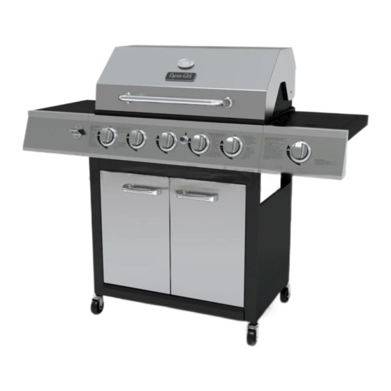
GAS GRILL WITH
SEAR SIDE BURNER
Model #DGF510SSP/DGF510SSP-D
1
5-BURNER LP
Français p. 33
Français p.
Español p. 63
Español p.
Rev. 11/4/14
XX
XX
Advertisement
Table of Contents

Related Manuals for Dyna-Glo DGF510SSP


Summary of Contents for Dyna-Glo DGF510SSP
- Page 1 5-BURNER LP GAS GRILL WITH SEAR SIDE BURNER Model #DGF510SSP/DGF510SSP-D Français p. 33 Français p. Español p. 63 Español p. ANS Z21.58b- 2012 CSA 1.6b- 2012 Outdoor Cooking Gas Appliances ATTACH YOUR RECEIPT HERE Serial Number _____________________________ Purchase Date ______________________ Questions, problems, missing parts? Before returning to your retailer, call our customer service department at 1-877-447-4768, 8:30 a.m.
-
Page 2: Table Of Contents
TABLE OF CONTENTS Safety Information ........................3 Package Contents ........................5 Hardware Contents ........................6 Preparation ..........................6 Assembly Instructions ........................ 7 Operation Instructions ......................... 19 Care and Maintenance ......................... 24 Troubleshooting ........................... 27 Warranty ............................29 Replacement Parts List ......................30 Assembler/Installer: This manual contains important information necessary for the proper assembly and safe use of this appliance. -
Page 3: Safety Information
SAFETY INFORMATION Please read and understand this entire manual before attempting to assemble, operate or install the product. If you have any questions regarding the product, please call customer service at: 1-877-447-4768, 8:30 a.m. – 4:30 p.m., CST, Monday – Friday. DANGER •... - Page 4 SAFETY INFORMATION WARNING • Do not place the grill under overhead combustible construction or awnings. Minimum clearance from sides and back of unit to combustible construction, 36 inches (914.4mm) from sides and 36in 36in 914.4mm back. 914.4mm NOTE: The installation must conform with local codes or, in the absence of local codes, with either the National Fuel Gas Code, ANSI Z223.1/NFPA 54, Natural...
-
Page 5: Table Of Contents
PACKAGE CONTENTS PART DESCRIPTION QUANTITY PART DESCRIPTION QUANTITY Side Burner Grease Pan Lid Handle Assembly Cart Left Side Panel Assembly Temperature Gauge Door Handle Grill Body Left Door Assembly Control Knob Upper Front Door Brace Grease Pan Cart Rear Panel Grease Cup Bottom Shelf Warming Rack... -
Page 6: Package Contents
HARDWARE CONTENTS (shown actual size) Door M4x10 M6x16 Plain Upper Wing Screw Screw Spring Plain Washer Hinge Washer Washer Qty. 4 Qty. 2 Qty. 2 Qty. 30 Qty. 16 Qty. 16 Qty. 8 M10-M6 Wrench Qty. 1 PREPARATION Before beginning assembly of product, make sure all parts are present. Compare parts with package contents list on previous page and hardware contents above. -
Page 7: Assembly Instructions
ASSEMBLY INSTRUCTIONS Attach Lower front cart frame (Y) to Bottom shelf (U) with 2 M6x16 screws (AA), and loosen the tank screw on the Bottom shelf (U), keep about 5mm clearance with flange in the tank nesting hole as shown. Hardware Used M6x16 Screw Attach Cart left side panel assembly (P) and... -
Page 8: Locking Swivel Caster
ASSEMBLY INSTRUCTIONS Attach 2 Locking swivel casters (V) and 2 Non-locking swivel casters (W) to Cart left side panel assembly (P) and Cart right side panel assembly (A1) with M6-M10 wrench (HH). Hardware Used M6-M10 Wrench Attach Cart rear panel (T) to Cart left side panel assembly (P) and Cart right side panel assembly (A1) with 4 M6x16 screws (AA), Spring washers (BB), and Plain washers (CC). - Page 9 ASSEMBLY INSTRUCTIONS Attach Upper front door brace (S) to Cart left side panel assembly (P) and Cart right side panel assembly (A1) with 4 M6x16 screws (AA), Spring washers (BB), and Plain washers (CC). Hardware Used M6x16 Screw M6 Spring Washer M6 Plain Washer Attach Magnet (X) to Bottom shelf (U) with 2 M4x10 screws (DD).
-
Page 10: Door Handle
ASSEMBLY INSTRUCTIONS Attach Door handle (Q) to Left door assembly (R) and Right door assembly (Z), then attach Match holder (B1) to Right door assembly (Z) with 4 M4X10 screws (DD) and M4 Plain washers (EE). Hardware Used M4x10 Screw M4 Plain Washer Insert the bottom axis in the Left door assembly (R) into the hole on the Lower front cart frame... -
Page 11: Assembly Instructions
ASSEMBLY INSTRUCTIONS Attach Lid handle assembly (A) to Grill body (C), 2 M6 wing nuts (GG), Spring washers (BB), and Plain washers (CC). Hardware Used M6 Wing Nut M6 Spring Washer M6 Plain Washer First, remove pre-assembled Wing nut and Plain washer from Temperature gauge (B), then attach Temperature gauge (B) to Grill body (C). - Page 12 ASSEMBLY INSTRUCTIONS Carefully place the Grill body (C) onto Cart left side panel assembly (P) and Cart right side panel assembly (A1). Adjust the Grill body (C) so that the holes in the Grill body (C) are aligned with holes in the tabs of Cart left side panel assembly (P) and Cart right side panel assembly (A1).
- Page 13 ASSEMBLY INSTRUCTIONS Insert 2 M6x16 screws (AA) in right side of Grill body (C) as shown, leaving 5mm of threads exposed. Align key hole in Right side table assembly (L) with the 2 screws just inserted in the Grill body (C), and insert 3 M6x16 screws (AA) in the remaining holes in the Grill body (C).
- Page 14 ASSEMBLY INSTRUCTIONS First, remove the side burner and keep the 2 screws that were removed. Secure side burner valve assembly and Side burner control knob bezel (M) to Right side burner table assembly (L) with 2 M4X10 screws (DD), then install the Side side burner to Right side burner table assembly Burner...
- Page 15 ASSEMBLY INSTRUCTIONS Slide Control knob (D) over valve stem. Remove the ignitor cap, insert AA battery (1.5V) (N) into the ignitor body with positive ‘+’ end facing out, replace the ignitor cap. Open the lid, place 5 Heat tents (I) on the inside of the Grill body (C)
- Page 16 ASSEMBLY INSTRUCTIONS Place 3 Cooking grates (H) into Grill body (C) as illustrated in the figure. Secure Warming rack (G) into Grill body (C). NOTE: Insert the Warming rack (G) into the four holes located on both sides of Grill body (C).
- Page 17 ASSEMBLY INSTRUCTIONS Open the left door assembly (R) and right door assembly (Z),insert hose/regulator assembly into the cart assembly through the clearance above cart Right side panel assembly (A1). Place gas cylinder (sold separately) into the nesting hole located in the Bottom shelf (U).
-
Page 18: Operation Instructions
OPERATION INSTRUCTIONS CHECKING FOR LEAKS After all connections are made, check all connections and fittings on the LP gas tank valve, gas hose and regulator for leaks with a water and soap solution. To prevent fire or explosion while testing for a leak: •... - Page 19 OPERATION INSTRUCTIONS CONNECTING GAS CYLINDER The propane gas supply cylinder to be used must be constructed and marked in accordance with the Specifications for LP Gas Cylinders of the U.S. Department of Transportation (D.O.T.) or the National Standard of Canada, CAN/CSA-B339, Cylinders, Spheres and Tubes for Transportation of Dangerous Goods;...
- Page 20 OPERATION INSTRUCTIONS NOTE: Other cylinders may be acceptable for use with this appliance provided they are compatible with the appliance nesting hole and retention means. Refer to Step 19 of the Assembly Instructions for correct cylinder to cylinder holder connection. WARNING ALL INSTRUCTIONS AND SAFEGUARDS ON THIS PAGE MUST BE FOLLOWED TO PREVENT FIRE, DAMAGE AND/OR INJURY.
- Page 21 OPERATION INSTRUCTIONS Lighting The Grill Before first use: Remove all hangings or plastic straps, if present. Before you cook on your new gas grill, it is important to clean your grill with heat. To do this, operate the grill for approximately 15 minutes with the lid closed and the control knob in the highest position.
- Page 22 OPERATION INSTRUCTIONS LIGHTING THE GRILL WITH A MATCH 1. Open the lid. 2. Insert a match in the end of the match holder that is installed on the inside of the cabinet door. 3. Light the match. 4. Immediately place the lit match through the spaces in the grill gates near the ports of the burner between the heat tents as shown.
-
Page 23: Care And Maintenance
CARE AND MAINTENANCE Cooking Grates The best time to ‘burn-off’ the cooking grates is after every use (approx. 15 minutes). The grill is already hot from cooking thus requiring less fuel to obtain necessary temperature for ‘burn-off’. To ‘burn off’ or heat clean your grill, turn the burners to highest position and run for 15 minutes with the lid closed. - Page 24 CARE AND MAINTENANCE Burner Assembly Removing The Burner Assembly Warming Rack Cooking 1. Make sure all control knobs are in the OFF Grates position, gas supply valve is closed, and the gas hose is disconnected from the gas supply. Heat Tents 2.
- Page 25 CARE AND MAINTENANCE Cleaning the Burner Assembly – Make sure the grill is cool 1. Ensure all burner ports are clear of clogs. Use of a pin or paper clip works well. 2. Ensure burner is free of any damage. If damage is found, replace with new burner. 3.
-
Page 26: Troubleshooting
CARE AND MAINTENANCE The electronic ignition requires 1 “AA” alkaline battery, which is included. WARNING DO NOT mix old and new batteries. DO NOT mix alkaline, standard (Carbon-Zinc), or rechargeable (Nickel-Cadmium) batteries. DO NOT dispose of batteries in fire. Improper disposal may cause batteries to leak or explode. TROUBLESHOOTING If you have any questions regarding the product, please call customer service at 1-877-447-4768, 8:30 a.m. - Page 27 TROUBLESHOOTING PROBLEM POSSIBLE CAUSE CORRECTIVE ACTION The burner will not 1. Match not reaching burners 1. Use match holder found in light with a match. (when holding match with cabinet door. hand). 2. Check fuel level and refill tank if 2.
-
Page 28: Warranty
GHP Group Inc. 6440 W. Howard Street Niles, Il, USA 60714-3302 Item Name: 5-Burner LP Gas Grill with Sear Side Burner Model #: DGF510SSP/DGF510SSP-D Main burner total rated BTU: 60,000 BTU/Hr Side burner rated BTU: 15,000 BTU/Hr... -
Page 29: Replacement Parts List
REPLACEMENT PARTS LIST... - Page 30 REPLACEMENT PARTS LIST For replacement parts, call our customer service department at 1-877-447-4768, 8:30 a.m. – 4:30 p.m., CST, Monday – Friday. PART DESCRIPTION PART # Temp gauge assembly 70 - 04 -100 Badge 104 - 22006 Lid handle assembly 70 - 01 -173 Lid pivot pin-with cotter pin 70 - 01 -174...
- Page 31 REPLACEMENT PARTS LIST PART DESCRIPTION PART # Magnet bracket 70 - 09 - 117 Cylinder retention screw assembly 70 - 09 - 118 70 - 05 - 100 Non-locking swivel caster Locking swivel caster 70 - 05 - 101 Lower front cart frame 70 - 01 - 201 Bottom shelf 70 - 01 - 202...
- Page 32 BARBECUE AU GAZ LP À 5 BRÛLEURS AVEC BRÛLEUR SEAR DE CÔTÉ Modele #DGF510SSP/DGF510SSP-D ANS Z21.58b- 2012 CSA 1.6b- 2012 Cuisine de plein air Appareils à gaz JOIGNEZ VOTRE REÇU ICI Numéro de série_____________________________ Date d’achat _____________________ Des questions, des problèmes, des pièces manquantes? Avant de retourner l’article au détaillant, appelez notre service à...
- Page 33 TABLE DES MATIÈRES Consignes de sécurité ........................ 35 Contenu de l’emballage ......................37 Quincaillerie incluse ........................38 Préparation ..........................38 Instructions pour l’assemblage ....................39 Mode d’emploi ..........................51 Entretien ............................56 Dépannage ..........................59 Garantie ............................61 Liste des pièces de rechange ....................62 Assembleur ou installateur : Le présent manuel contient des renseignements importants qui permettent d’assembler l’appareil de façon adéquate et de l’utiliser en toute sécurité.
- Page 34 CONSIGNES DE SÉCURITÉ Assurez-vous de lire et de comprendre l’intégralité de ce manuel avant de tenter d’assembler, d’utiliser ou d’installer le produit. Si vous avez des questions concernant ce produit, veuillez téléphoner au service à la clientèle au 1-877-447-4768, 08:30-16 heures 30, HNC, du lundi - vendredi.
- Page 35 CONSIGNES DE SÉCURITÉ AVERTISSEMENT • Ne pas utiliser cet appareil sous une surface combustible ou un auvent. Dégagement minimal entre les parois latérales et l’arrière de l’appareil et la construction combustible (914,4 mm (36 po) à partir des parois latérales et 914,4 mm 36in 36in 914.4mm...
- Page 36 CONTENU DE L’EMBALLAGE PIÈCE DESCRIPTION QTÉ PIÈCE DESCRIPTION QTÉ Plateau à graisse du brûleur latéral Poignée Panneau gauche du chariot Indicateur de température Poignée de porte Boitier du barbecue Porte gauche Bouton de commande Support supérieur des portes Plateau à graisse Panneau arrière du chariot Récipient à...
- Page 37 QUINCAILLERIE INCLUSE (grandeur réelle) M4x10 M6x16 Rondelle Superieur Ecrou a Rondelle a Rondelle Plate de la Oreilles Ressort Plate Porte Qte. 30 Qte. 8 Qte. 4 Qte. 2 Qte. 16 Qte. 16 Qte. 2 M10-M6 Qte. 1 PRÉPARATION Avant de commencer l’assemblage du produit, assurez-vous d’avoir toutes les pièces. Comparez les pièces dans l’emballage avec la liste des pièces de la page précédente et la quincaillerie indiquée ci-dessus.
- Page 38 INSTRUCTIONS POUR L’ASSEMBLAGE Fixez la pièce frontale inférieure du chariot (Y) à l’étagère inférieure (U) avec 2 vis M6x16 (AA), et desserrez la vis de la bouteille sur l’étagère inférieure (U), afin d’espacer le rebord du trou de la bouteille d’environ 5mm, comme illustré. Quincaillerie utilisée M6x16 Vis Fixez le panneau gauche du chariot (P) et...
- Page 39 INSTRUCTIONS POUR L’ASSEMBLAGE Fixez 2 roulettes à blocage (V) et 2 roulettes sans blocage (W) au panneau gauche du chariot (P) ainsi qu’au panneau droit du chariot (A1) avec la clé M10-M6 (HH). Quincaillerie utilisée M6-M10 Cle Fixez le panneau arrière du chariot (T) au panneau gauche du chariot (P) ainsi qu’au panneau droit du chariot (A1) avec 4 vis M6x16 (AA), 4 rondelles à...
- Page 40 INSTRUCTIONS POUR L’ASSEMBLAGE Fixez le support supérieur des portes (S) au panneau gauche du chariot (P) ainsi qu’au panneau droit du chariot (A1) avec 4 vis M6x16 (AA), 4 rondelles à ressort (BB), et 4 rondelles plates (CC). Quincaillerie utilisée M6x16 Vis M6 Rondelle a Ressort M6 Rondelle Plate...
- Page 41 INSTRUCTIONS POUR L’ASSEMBLAGE Fixez les poignées de porte (Q) à la porte gauche (R) et à la porte droite (Z) et fixez le porte-allumettes (B1) à la porte droite (Z) avec 4 vis M4X10 (DD) et 4 rondelles plates M4 (EE). Quincaillerie utilisée M4x10 Vis M4 Rondelle Plate...
- Page 42 INSTRUCTIONS POUR L’ASSEMBLAGE Fixez la poignée du couvercle (A) du barbecue (C) avec 2 écrous à oreilles M6 (GG), 2 rondelles à ressort (BB) et 2 rondelles plates (CC). Quincaillerie utilisée M6 Ecrou a Orellies M6 Rondelle a Ressort M6 Rondelle Plate Premièrement, enlevez l’écrou à...
- Page 43 INSTRUCTIONS POUR L’ASSEMBLAGE Installez prudemment le boitier du barbecue (C) sur le panneau gauche du chariot (P) et sur le panneau droit du chariot (A1). Ajustez le boitier du barbecue (C) afin que les trous du boitier du barbecue (C) soient alignés avec les trous des languettes du panneau gauche du chariot (P) et du panneau droit du chariot (A1).
- Page 44 INSTRUCTIONS POUR L’ASSEMBLAGE Insérez 2 vis M6x16 (AA) dans le côté droit du boitier du barbecue (C), mais le filetage des vis doit laisser un espace de 5mm, comme illustré. Alignez les trous du table brûleur latéral droite (L) aux 2 vis que vous venez d’insérer dans le boitier du barbecue (C).
- Page 45 INSTRUCTIONS POUR L’ASSEMBLAGE Premièrement, il faut enlever les 2 vis du brûleur latéral afin d’enlever le brûleur latéral (garder les 2 vis). Fixez la valve du brûleur latéral et la couronne du bouton de commande du brûleur latéral (M) aux table brûleur latéral droite (L) avec 2 vis M4X10 (DD).
- Page 46 INSTRUCTIONS POUR L’ASSEMBLAGE Glissez le bouton de commande (D) sur la tige de la soupape. Enlevez le capuchon de l’allumeur et insérez 1 pile AA (1,5V) (N) dans le compartiment de l’allumeur avec la borne positive (+) qui doit être vers l’extérieur. Rem ettez le capuchon de l’allumeur.
- Page 47 INSTRUCTIONS POUR L’ASSEMBLAGE Placez 3 grilles de cuisson (H) à l’intérieur du boitier du barbecue (C), comme illustré. Installez le chauffe-plat (G) dans le boitier du barbecue (C). NOTE : Installez le chauffe-plat (G) en insérant ses pivots dans les 4 trous sur les côtés du barbecue.
- Page 48 INSTRUCTIONS POUR L’ASSEMBLAGE Ouvrez la porte gauche du chariot (R) et la porte droite du chariot (Z). Insérez le tuyau/ détendeur dans le chariot en le passant dans l’ouverture au-dessus du panneau droit (A1). Placez la bouteille de gaz (vendue séparé ment) sur le trou qui se trouve sur l’étagère du bas (U).
- Page 49 MODE D’EMPLOI DÉTECTION DES FUITES Après avoir fait tous les branchements, vérifiez s’il y a des fuites en vaporisant de l’eau savonneuse sur le robinet du réservoir de propane liquéfié, le tuyau de gaz et le régulateur. Pour prévenir les incendies ou les explosions lorsque vous tentez de détecter les fuites : •...
- Page 50 MODE D’EMPLOI RACCORD DE LA BOUTEILLE DE GAZ La bouteille de propane liquéfié utilisée doit être fabriquée et identifiée conformément aux normes pour les bouteilles de propane liquéfié du Specifications for LP Gas Cylinders of the U.S. Department of Transportation (D.O.T.) or the National Standard of Canada, CAN/CSA-B339, Cylinders, Spheres and Tubes for Transportation of Dangerous Goods;...
- Page 51 MODE D’EMPLOI REMARQUE : Vous pouvez utiliser d’autres bouteilles avec cet appareil, pourvu qu’elles conviennent au trou pour la bouteille et aux dispositifs de fixation. Consultez l’étape 19 des instructions pour l’assemblage pour connaître la manière adéquate de fixer une bouteille au support de bouteille. AVERTISSEMENT TOUTES LES INSTRUCTIONS ET MESURES DE SÉCURITÉ...
- Page 52 MODE D’EMPLOI ALLUMAGE DU BARBECUE Avant la première utilisation : Retirez toutes les étiquettes et les courroies de plastique, le cas échéant. Avant d’utiliser votre nouveau barbecue au gaz, il est nécessaire de le nettoyer à la chaleur. Pour ce faire, faites fonctionner le barbecue pendant une quinzaine de minutes;...
- Page 53 MODE D’EMPLOI ALLUMAGE DU BARBECUE AVEC UNE ALLUMETTE 1. Insérez une allumette à l’extrémité du support à allumettes situé à l’intérieur de la porte du charriot. 2. Allumez l’allumette. 3. Insérez sans tarder l’allumette enflammée dans le trou de 20 mm (0,75 po) situé sur le côté du corps du barbecue le plus près du brûleur que vous souhaitez allumer.
- Page 54 ENTRETIEN GRILLES DE CUISSON Il est recommandé de brûler les résidus sur la grille de cuisson environ quinze minutes après chaque utilisation. Le barbecue est encore chaud et nécessite donc moins de gaz pour atteindre la chaleur nécessaire pour brûler les résidus. Pour brûler les résidus ou nettoyer votre barbecue par la chaleur, allumez les brûleurs à...
- Page 55 ENTRETIEN ENSEMBLE DE BRÛLEUR Grille de maintien au chaud RETRAIT DE L’ENSEMBLE DE BRÛLEUR Grilles de 1. Assurez-vous que tous les boutons de cuisson commande sont à la position « OFF » (arrêt), que le robinet du réservoir de Plaques propane liquéfié...
- Page 56 ENTRETIEN NETTOYAGE DE L’ENSEMBLE DE BRÛLEUR – Assurez-vous que le barbecue est refroidi. 1. Fermez l’alimentation en gaz en tournant les boutons de commande du barbecue et le robinet de la bouteille de propane. 2. Retirez la bouteille de gaz propane liquéfié du tuyau et du régulateur. 3.
- Page 57 ENTRETIEN L’allumage électronique nécessite une pile alcaline « AA » incluse. AVERTISSEMENT N’utilisez PAS de vieilles piles avec des piles neuves. NE combinez PAS des piles alcalines avec des piles ordinaires (carbone-zinc) ou avec des piles rechargeables (nickel-cadmium). NE jetez PAS les piles au feu. Une mise au rebut inadéquate pourrait causer une fuite ou faire exploser les piles. DÉPANNAGE Si vous avez des questions, veuillez téléphoner au service à...
- Page 58 DÉPANNAGE PROBLÈME CAUSE POSSIBLE MESURE CORRECTIVE Le brûleur ne 1. L’allumette n’atteint pas les 1. Utilisez le support à allumettes s’allume pas à l’aide brûleurs (lorsque vous la situé dans la porte de l’armoire. d’une allumette. tenez d’une main). 2. L’alimentation en gaz est 2.
- Page 59 6440 W. Howard Street Niles, IL, USA 60714-3302 Nom de l’article : Barbecue au gaz LP à 5 brûleurs avec brûleur sear de côté No de modèle : DGF510SSP/DGF510SSP-D Capacité nominale : 60,000 BTU/Hr Brûleur latéral nominale : 15,000 BTU/Hr...
- Page 60 LISTE DES PIÈCES DE RECHANGE...
- Page 61 LISTE DES PIÈCES DE RECHANGE Pour les pièces détachées, appelez notre service à la clientèle au 1-877-447-4768, 8 heures 30-16h30, HNC, du lundi - vendredi. PART DESCRIPTION PART # Assemblage indicateur de température 70 - 04 -100 Plaque 104 - 22006 Poignée du couvercle 70 - 01 -173 Pivot du couvercle avec goupille fendue...
- Page 62 LISTE DES PIÈCES DE RECHANGE PART DESCRIPTION PART # Plaque à aimant 70 - 09 - 117 Vis de retenue cylindrique 70 - 09 - 118 Roulette sans blocage 70 - 05 - 100 Roulette à blocage 70 - 05 - 101 Pièce inférieure du chariot 70 - 01 - 201 Étagère du bas...
- Page 63 PARRILLA A GAS PL DE 5 FOGONES CON QUEMADOR LATERAL Modelo # DGF510SSP/DGF510SSP-D ANS Z21.58b- 2012 CSA 1.6b- 2012 Cocina al aire libre aparatos de gas ADJUNTE SU RECIBO AQUÍ Número de serie _______________________ Fecha de compra __________________ ¿Preguntas, problemas, piezas faltantes? Antes de volver a la tienda, llame a nuestro Departamento de Servicio al Cliente al 1-877-447-4768, de 8:30 am - 4:30 pm, hora central, de lunes - viernes o envíe un correo electrónico a customerservice@ghpgroupinc.com.
- Page 64 INDICE Informacion de seguridad ......................67 Contenido del paquete ....................... 69 Aditamentos ..........................70 Preparacion ..........................70 Instrucciones de ensamblaje ....................... 71 Instrucciones de funcionamiento ....................83 Cuidado y mantenimiento ......................88 Solucion de problemas ........................ 91 Garantla ............................93 Lista de piezas de repuesto .......................
- Page 65 INFORMACION DE SEGURIDAD Lea y comprenda completamente este manual antes de intentar ensamblar, usar o instalar el producto. Si tiene preguntas relacionadas con el producto, lIame al Servicio al Cliente al: 1-877-447-4768, de 8:30 am - 4:30 pm, hora central, de lunes - viernes. PELIGRO •...
- Page 66 INFORMACIÓN DE SEGURIDAD ADVERTENCIA • No coloque la parrilla debajo de construcciones o cobertizos inflamables. Debe haber un espacio de separación mínimo de 91,44 cm (36”) desde los lados y la parte posterior de la unidad 36in 36in 914.4mm hasta construcciones de material 914.4mm combustible.
- Page 67 CONTENIDO DEL PAQUETE PIEZA DESCRIPCIÓN CANT. PIEZA DESCRIPCIÓN CANT. Cesta izquierda lateral de panel de Montaje de la manija de la tapa ensamblado Indicador de temperatura Haladera Cuerpo de la parrilla Ensamble puerta izquierda Perrilla de control Abrazadera de puerta frontal superior Bandeja para la grasa Carrito panel trasero Rejilla recalentamiento...
- Page 68 ADITAMENTOS (se muestran en tamano real) Puerta M4x10 M6x16 Arandela Superior Ala de Tornillo Tornillo Arandela Arandela Bisagra Tuerca Resorte Cant. 16 Cant. 4 Cant. 2 Cant. 30 Cant. 16 Cant. 8 Cant. 2 M10-M6 Llave Cant. 1 PREPARACION Antes de comenzar a ensamblar el praducto, asegurese de tener todas las piezas. Compare las piezas con la lista del contenido del paquete de la pagina anterior y los aditamentos que aparecen arriba.
- Page 69 INSTRUCCIONES DE ENSAMBLAJE Adjuntar el marco frontal del carrito (Y) a la plataforma inferior (U) con 2 (AA) tornillos M6x16, y aflojar el tornillo del tanque en el estante inferior (U), mantener sobre holgura de 5 mm con brida en el agujero de encaje del tanque como se muestra.
- Page 70 INSTRUCCIONES DE ENSAMBLAJE Coloque 2 ruedecillas giratorias bloqueadas (v) y 2 ruedecillas giratorias desbloqueadas (W) al tablero lateral del carrito (P) y al tablero del carro de montaje lateral derecho (A1) con la llave M10-M6 (HH) Aditamentos utilizados M6-M10 Llave Sujete el tablero del carrito (T), al conjunto izquierdo del carrito del tablero lateral (P) y el carro de montaje panel lateral derecho...
- Page 71 INSTRUCCIONES DE ENSAMBLAJE Adjuntar la abrazadera de la puerta frontal superior (S) en el carrito izquierda conjunto de tablero lateral (P) y el carro de montaje del tablero lateral derecho (A1) con 4 M6x16 (AA) tornillos, (BB) resortes de arandelas, y (CC) arandelas.
- Page 72 INSTRUCCIONES DE ENSAMBLAJE Coloque la agarradera de la puerta (Q) para el montaje de la puerta izquierda (R) y conjunto de la puerta derecha (Z), y adjuntar el porta fósforos (B1) al conjunto de la puerta derecha (Z) con 4 tornillos M4x10 DD) y M4 Arandelas (EE).
- Page 73 INSTRUCCIONES DE ENSAMBLAJE Coloque el conjunto del mango de la tapa (A) al cuerpo de la parrilla (C) 2 M6 haladera con tuerca (GG), (BB) resorte de arandelas, y (CC) arandelas de fricción. Aditamentos utilizados M6 Ala de Tuerca M6 Resorte de Arandela M6 Arandela En primer lugar, quite la haladera con tuerca pre-ensamblada y la arandela del indicador de...
- Page 74 INSTRUCCIONES DE ENSAMBLAJE Coloque con cuidado el cuerpo de la parrilla (C) en la cesta izquierda conjunto del tablero lateral (P) y el carro de montaje tablero lateral derecho (A1), Ajuste la caja de la parrilla (C) de manera que los orificios de la caja de la parrilla (C) están alineados con agujeros en las pestañas de la izquierda del carrito ensam blados a un lado del tablero (P) y el carro...
- Page 75 INSTRUCCIONES DE ENSAMBLAJE Instale 2 M6x16 (AA) tornillos al lado derecho del cuerpo de la parrilla (C) como se muestra, dejando 5 mm de roscas expuestas, alinee el agujero clave en conjunto de la mesa lateral izquierda (L) a los 2 tornillos apenas instalados en el cuerpo de la parrilla (C), e instalar otros 3 M6x16 (AA) tornillos en los agujeros que quedan en el cuerpo de la parrilla (C).
- Page 76 INSTRUCCIONES DE ENSAMBLAJE En primer lugar, desinstale el quemador lateral y mantener la desinstalación de 2 tornillos, asegure el montaje de la válvula del quemador lateral del quemador lateral con bisel y botón de mando (M) al conjunto de la mesa del quemador lateral derecho (L) con 2 (DD) tornillos Quemador lateral...
- Page 77 INSTRUCCIONES DE ENSAMBLAJE Deslice la perilla de control (D) sobre el vástago de la válvula. Quite la tapa del encendedor, inserte la batería AA (1.5V) (N) en el cuerpo del encendedor con el positivo “+” apuntando hacia fuera, vuelva a colocar la tapa del encendedor.
- Page 78 INSTRUCCIONES DE ENSAMBLAJE Coloque las rejillas para cocinar 3 (H) en caja de la parrilla (C) como se ilustra en la figura. Asegure la rejilla de calentamiento (G) en el cuerpo de la parrilla (C). NOTA: Inserte la rejilla de calentamiento (G) en los cuatro orificios situados a ambos lados del cuerpo de la parrilla.
- Page 79 INSTRUCCIONES DE ENSAMBLAJE Abra el conjunto del tablero lateral del carrito izquierda (P) y el carro de montaje del tablero lateral derecho (A1), inserte conjunto de la manguera / regulador en el conjunto del tablero a través del espacio libre por encima del conjunto de la cesta del tablero lateral derecho (A1), el lugar cilindro de gas (se vende por separado) en el agujero de encaje...
- Page 80 INSTRUCCIONES DE FUNCIONAMIENTO BÚSQUEDA DE FUGAS Después de hacer todas las conexiones, verifique que ninguna de las conexiones y los conectores de la válvula del tanque de gas PL, la manguera de gas ni el regulador tenga fugas con una solución de agua y jabón.
- Page 81 INSTRUCCIONES DE FUNCIONAMIENTO CONEXIÓN DEL CILINDRO DE GAS El cilindro de suministro de gas propano que se utilizará debe estar fabricado y marcado según las Specifications for LP-Gas Cylinders of the U.S. Department of Transportation (D.O.T.) or the National Standard of Canada, CAN/CSA-B339, Cylinders, Spheres and Tubes for Transportation of Dangerous Goods;...
- Page 82 INSTRUCCIONES DE FUNCIONAMIENTO NOTA: Es posible que otros cilindros sean aceptables para su uso con este electrodoméstico si es que son compatibles con el orificio de alojamiento y los medios de retención del electrodoméstico. Consulte el Paso 19 de las Instrucciones de ensamblaje para conocer la conexión correcta del cilindro al soporte del cilindro. ADVERTENCIA SE DEBEN SEGUIR TODAS LAS INSTRUCCIONES Y MEDIDAS DE SEGURIDAD DE ESTA PÁGINA PARA EVITAR INCENDIOS, DAÑOS Y/O LESIONES.
- Page 83 INSTRUCCIONES DE FUNCIONAMIENTO Encender la parrilla Antes del primer uso: Retire todos los ahorcamientos o correas de plástico, si está presente. Antes de cocinar en la parrilla de gas nuevo, es importante para limpiar su parrilla con el calor. Para ello, utilice el grill durante unos 15 minutos con la tapa cerrada y el botón de control en la posición más alta.
- Page 84 INSTRUCCIONES DE FUNCIONAMIENTO ENCENDIDO DE LA PARRILLA CON UN FÓSFORO 1. Coloque un fósforo en el extremo del contenedor de fósforos instalado en el interior de la puerta del gabinete. 2. Encienda el fósforo. 3. Inmediatamente introduzca el fósforo encendido en el orificio de 1,91 cm (0,75”) del costado del cuerpo de la parrilla que esté...
- Page 85 CUIDADO Y MANTENIMIENTO REJILLAS DE COCCIÓN El mejor momento para “quemar” la suciedad las rejillas de cocción es después de cada uso (aproximadamente 15 minutos). La parrilla ya está caliente desde la cocción, por lo tanto, requiere menos combustible para obtener la temperatura necesaria para “quemar” la suciedad. Para “quemar”...
- Page 86 CUIDADO Y MANTENIMIENTO ENSAMBLE DEL QUEMADOR Rejilla para Calentar EXTRACCIÓN DEL ENSAMBLE DEL QUEMADOR Parrilla de Cocción 1. Asegúrese de que todas las perillas de control se encuentran en la posición de OFF, que la válvula del tanque de PL está cerrada y Cubierta del Calor que el tanque está...
- Page 87 CUIDADO Y MANTENIMIENTO LIMPIEZA DEL ENSAMBLE DEL QUEMADOR – Asegúrese de que la parrilla esté fría 1. Corte el gas en las perillas de control y en el tanque de propano. 2. Desconecte el cilindro de gas PL de la manguera y el regulador. 3.
- Page 88 CUIDADO Y MANTENIMIENTO El encendido electrónico requiere 1 batería alcalina “AA”, que viene incluida. ADVERTENCIA NO mezcle baterías antiguas con nuevas. NO mezcle baterías alcalinas, estándar (carbono-zinc) o recargables (níquel-cadmio). NO se deshaga de las baterías en el fuego. Desechar las baterías indebidamente podría provocar que éstas exploten o tengan fugas.
- Page 89 SOLUCIÓN DE PROBLEMAS PROBLEMA CAUSA POSIBLE ACCIÓN CORRECTIVA El quemador no se 1. Use el soporte para fósforos que se 1. El fósforo no alcanza los luz con un fósforo. quemadores (al sostenerlo encuentra en la puerta del gabinete. con la mano). 2.
- Page 90 GHP Group Inc. 6444 W. Howard Street Niles, IL, USA 60714-3302 Nombre del artículo: Parrilla a Gas PL de 5 Fogones con Quemador Lateral Modelo #: DGF510SSP/DGF510SSP-D Clasificación de: 60,000 BTU/Hr BTU del quemador lateral nominal: 15,000 BTU/Hr...
- Page 91 LISTA DE PIEZAS DE REPUESTO...
- Page 92 LISTA DE PIEZAS DE REPUESTO Para obtener piezas de repuesto, llame a nuestro Departamento de Servicio al Cliente al 1-877-447-4768, de 8:30 am - 4:30 pm, hora central, de lunes - viernes. PARTE DESCRIPCION NO. DE PARTE Ensamble de medidor de tempura 70 - 04 -100 Insignia 104 - 22006...
- Page 93 LISTA DE PIEZAS DE REPUESTO PARTE DESCRIPCION NO. DE PARTE Soporte de imán 70 - 09 - 117 Ensamble de cilindro de tornillo de retención 70 - 09 - 118 Ruedicillas giatorias sin enclavamiento 70 - 05 - 100 Ruedicillas giatorias con enclavamiento 70 - 05 - 101 Marco frontal inferior de carrito 70 - 01 - 201...
Need help?
Do you have a question about the DGF510SSP and is the answer not in the manual?
Questions and answers