Table of Contents
Advertisement
Quick Links
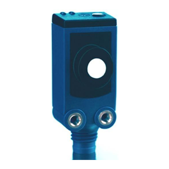
Product description
The sks sensor offers a non-contact-
measurement of the distance to an
object which must be positioned
within the sensor's detection zone.
The switched output is set in depen-
dance of the adjusted detect distan-
ce.
Via the push-button, the distance
and operating mode can be adjusted
(Teach-in). Two LEDs indicate operati-
on and the state of the switched
output. The output function is chan-
geable from NOC to NCC.
Operating manual
IO-Link
sks-15/CF/A
The sks sensor is IO-Link-capable in
accordance with IO-Link specification
Ultrasonic proximity switch
V1.1 and supports Smart Sensor Pro-
with one switching output and
file like Digital Measuring Sensor.
IO-Link interface
Safety notes
■ Read operating instructions pior to
Sensor adjustment with Teach-in procedure
1
Set detect point
Set detect point + 8%
- method A
- method B
Place object at position ➀
Place object at position ➀
Press push-button for about
Press push-button for about
3 s until LEDs flash
3 s until LEDs flash
simultaneously
simultaneously
both LEDs:
flash
both LEDs:
flash
mutually
mutually
Press push-button for
Press push-button for
about 3 s until both LEDs
about 1 s
flash mutually again
start-up.
■ Connection, installation and ad-
justment works may only be
carried out by expert personnel
■ No safety component according to
EU Machinery Directive
Proper use
sks ultrasonic sensors are used for
non-contact detection of objects.
Mounting
■ Mount the sensor at installation
site, Maximum torque: 0.5 Nm
■ Connect a connection cable to the
M8 device plug
Start-Up
■ Connect the power supply
■ Carry out the adjustment in accor-
ding with the diagram
1
2
1
85 %
Set two way reflective
Set window mode
barrier
Place object at position ➀
Place reflector at position ➀
Press push-button for about
Press push-button for about
3 s until LEDs flash
3 s until LEDs flash
simultaneously
simultaneously
both LEDs:
flash
both LEDs:
flash
mutually
mutually
Place object at position ➁
Press push-button for
Press push-button for
about 1 s
about 10 s
Normal operating mode
Set switched output
Factory setting
■ Operating with one detect point
■ Switched output on NOC
■ Detect points at operating range
■ Filter F01
■ Filter strength P00
2
4
1
3
colour
1
+U
brown
B
3
-U
blue
B
4
F
black
2
-*
white
Fig. 1: Pin assignment with view of the sensor
plug and color coding of the microsonic
connection cables
* Do not connect
Operating modes
Three operating modes are available
for the switches output:
Enable/disable Teach-in
Set NOC/NCC
push-button
Switch off power supply
While pressing the push-
button switch on power
Keep push-button pressed
Press button for about 13 s
for about 3 s until both
until LEDs flash mutually
LEDs flash simultaneously
green LED:
flashes
green LED:
yellow LED:
on: NOC
yellow LED:
off: NCC
To change output characte-
To enable/disable Teach-in
ristic press push-button
press push-button
for about 1 s
for about 1 s
Wait for 10 s
Wait for 10 s
■ Operation with one switching point
The switched output is set if the ob-
ject falls below the set detect point.
■ Window mode
The switched output is set if the object
is outside the set window margins.
■ Two-way reflective barrier
The switched output is set if the ob-
ject is located between the sensor
and reflector.
Checking operation mode
■ In normal mode shortly press the
push-button.
The green LED stops shining for one
second, then it will show the current
operating mode:
1 x flashing = operation with one
switching point
2 x flashing = window mode
3 x flashing = reflective barrier
Reset to factory setting
Switch off power supply
While pressing the push-
button switch on power
supply
supply
Keep push-button pressed
for about 13 s until only
one LED flashes
flashes
on: push-button
enabled
off: push-button
disabled
Normal operating mode
Further settings
After a break of three seconds, the
green LED shows the output func-
tion:
1 x flashing = NOC
2 x flashing = NCC
Maintenance
microsonic sensors are maintenance-
free. In case of excess caked-on dirt
we recommend cleaning the white
sensor surface.
Notes
■ Every time the power supply is swit-
ched on, the sensor detects its actu-
al operating temperature and trans-
mits it to the internal temperature
compensation. The adjusted value is
taken over after 45 seconds.
■ If the sensor was switched off for
at least 30 minutes and after po-
wer on the the switched output is
not set for 30 minutes a new ad-
justment of the internal tempera-
ture compensation to the actual
mounting conditions takes place.
■ The sks sensor has a blind zone
whithin which distance measure-
ments are not possible.
■ In the normal operating mode, an
illuminated yellow LED signals the
switched
output
is
switched
through.
■ In the »Set detect point – method A«
Teach-in procedure the actual dis-
tance to the object is taught to the
sensor as the detect point. If the ob-
ject moves towards the sensor (e.g.
with level control) then the taught
distance is the level at which the sen-
sor has to switch the output.
■ If the object to be scanned moves
into the detection area from the
side, the »Set detect point +8 % –
method B« Teach-in procedure
should be used. In this way the
switching distance is set 8 %
further than the actual measured
distance to the object. This ensu-
res a reliable switching distance
even if the height of the objects
varies slightly, see fig. 2.
■ In the »Two-way reflective barrier«
operating mode, the object has to
be within the range of 0-85 % of
the set distance.
Advertisement
Table of Contents

Related Manuals for Microsonic sks-15/CF/A


Summary of Contents for Microsonic sks-15/CF/A
- Page 1 Fig. 1: Pin assignment with view of the sensor sks-15/CF/A The sks sensor is IO-Link-capable in second, then it will show the current mits it to the internal temperature plug and color coding of the microsonic Start-Up accordance with IO-Link specification operating mode: compensation. The adjusted value is connection cables ■...
- Page 2 2014/30/EU microsonic GmbH / Phoenixseestraße 7 / 44263 Dortmund / Germany / T +49 231 9 151-0 / F +49 231 975151-51 / E info@microsonic.de / W microsonic.de The content of this document is subject to technical changes. Specifications in this document are presented in a descriptive way only. They do not warrant any product features.
Need help?
Do you have a question about the sks-15/CF/A and is the answer not in the manual?
Questions and answers