Advertisement
Quick Links
PLEASE READ THESE INSTRUCTIONS CAREFULLY BEFORE
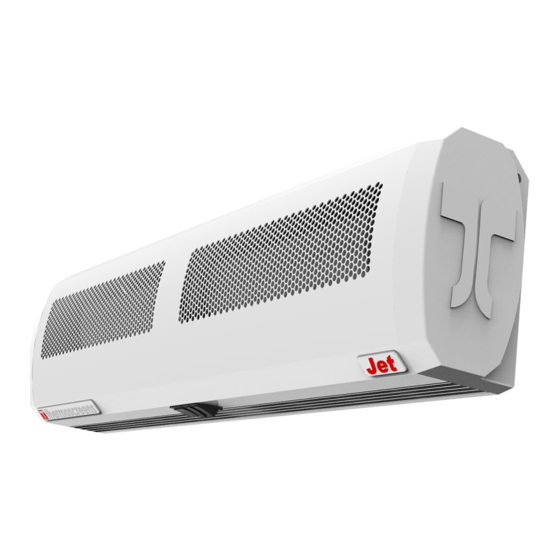
Figure 1: Jet Range General Assembly Drawing
CONTENTS
Remove from carton and check contents include:
•
Thermoscreens Jet heater unit
•
Mounting bracket
•
Cable gland (supplied loose)
For warranty purposes please retain your receipt as proof of
purchase.
INSTALLATION
The Jet heater is designed for surface mounting horizontally
above a door opening at a height of 1.8m minimum to 2.3m
maximum (from floor level to the underside of the appliance).
Multiple Jet heaters mounted side by side may be used for
wider doorways. The heater must be mounted internally
within a building and can be either wall or ceiling mounted.
Figure 2: Wall or Ceiling Mounting Options
Before fitting heater obtain suitable screws and wall plugs,
taking into account wall or ceiling type and unit weight (see
Table 1). The heater must not be located immediately below
a socket outlet. Do not cover or obstruct the air inlet or outlet
grilles as this can cause overheating and may cause a risk of
fire. Do not install heater in environments containing
flammable or explosive material.
Using the mounting bracket as a template determine optimum
location for the heater, place bracket on the wall or ceiling and
mark position of the two fixing holes (refer to 'B' in Figure 1).
Drill wall or ceiling accordingly and securely fix mounting
bracket into position.
4001260-4 IO
INSTALLATION AND RETAIN FOR FUTURE REFERENCE
JET 3, 4.5 & 6 Over Door
Installation, Operation and Maintenance Instructions
Model
JET 3
JET 4.5
JET 6
Table 1: Jet Over Door Heater Range
Figure 3: Mounting Bracket Alignment
Align and position mounting bracket into the two slots on the
rear plate of the heater (refer to Figure 3).
Ensure the serrated washer, at each end of the heater, is
positioned between the mounting bracket and the internal
hanging bracket (see Figure 4). Tilt and point heater into the
preferred direction and firmly tighten both fixing screws.
Using a Pozi No. 2 screwdriver the fixing screws are tightened
via access hole in each end cap.
Figure 4: Cross Sectional View of Mounting Bracket
ELECTRICAL CONNECTION
All electrical wiring and connections must be carried out by a
competent qualified electrician in accordance with the latest
edition of the IEE wiring regulations and/or local statutory
regulations.
1
Heaters.
Heat
Electrical
Weight
Output
Input (W)
(kg)
(kW)
3030
4.5
3.0/1.5
4540
5.5
4.5/2.25
6055
5.5
6.0/3.0
Advertisement

Related Manuals for Thermoscreens JET 3


Summary of Contents for Thermoscreens JET 3
- Page 1 JET 3, 4.5 & 6 Over Door Heaters. Installation, Operation and Maintenance Instructions PLEASE READ THESE INSTRUCTIONS CAREFULLY BEFORE INSTALLATION AND RETAIN FOR FUTURE REFERENCE Heat Electrical Weight Model Output Input (W) (kg) (kW) JET 3 3030 3.0/1.5 JET 4.5 4540 4.5/2.25...
- Page 2 WARRANTY If any problems are encountered, please contact your installer or supplier. Failing this please contact the Thermoscreens warranty department. All units are covered by a one year warranty. Subject to availability we undertake to repair or exchange this product.
Need help?
Do you have a question about the JET 3 and is the answer not in the manual?
Questions and answers