Table of Contents
Advertisement
Quick Links
1
INTRODUCTION
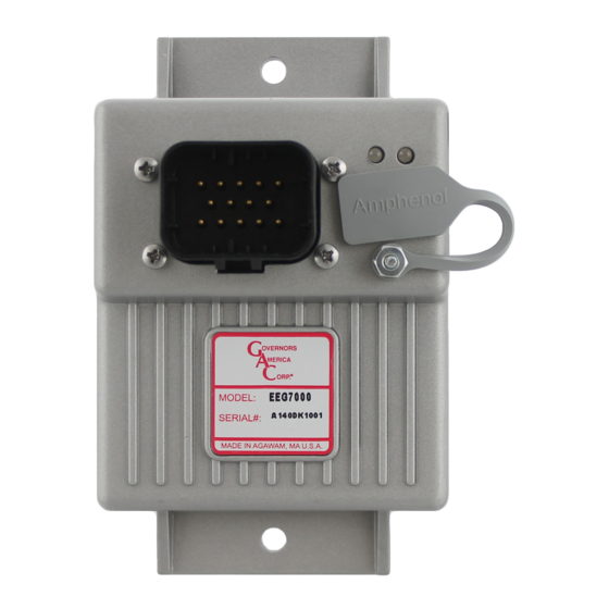
GAC's EEG7000 electronic digital speed controller is designed to regulate engine speed on
diesel and gaseous fueled engines. When paired with a GAC actuator the EEG7000 is a suit-
able upgrade for any mechanical governor system that needs flexibility, precision, and accurate
control of governed speed.
The EEG7000 is designed for industrial engine applications including generator sets, me-
chanical drives, pumps, compressors and off-road mobile equipment. The
adds the ability to monitor and set parameters from your PC. With CAN J1939 capability it
has the ability to accept TSC1 messages over USB as a mini engine control module (ECM).
It can be controlled directly over J1939 with aftermarket displays such as ComAp, Dynagen,
and Murphy – a solution for every application.
Mini-ECU, J1939 TSC1 Control capable with Diagnostic Messages (DM)
Š
Isochronous, variable, or customizable droop governing
Š
3 fixed speeds or variable speeds with Direct 0 – 5 V DC, 5 kΩ, or 4 – 20 mA Input
Š
Built-in USB port for easy configuration with free software
Š
Black smoke reduction, speed ramp control, load sharing/synchronizing option,
Š
Cummins EFC-capable
Built-in speed switch output for crank or overspeed
Š
Battery voltage, engine hour meter and service timer
Š
Fully sealed, IP67
Š
Multi- V DC
Š
Gaseous or Diesel
Š
Built-In Configurable Speed Switch Output
Š
2
EEG7000 SPECIFICATIONS
Performance
Isochronous Operation
Speed Range
Droop Range
Speed Ramp Time
Acceleration. Adj. Range
Deceleration. Adj. Range
Starting Fuel Adjustment
Actuator Ramp Rate
Actuator Begin Point
Overspeed Set Point
Crank Termination Set Point
Speed Switch Adjustment Range
Speed 1
Speed 2 & 3
Reverse Power Protection
Transient Voltage Protection
Load Share / Synchronization Input
Speed Sensor Signal Input
Speed Switch (SSW)
EEG7000 with GAConfig Tool
Electronic Digital Speed Controller
± 0.25 %
100 - 12 kHz
0.1 - 25 % regulation
25 to 2000 RPM/s
25 to 2000 RPM/s
1 to 100 %
0 to 100 %
400 to 6000 RPM
100 to 1000 RPM
1000 - 100000 Hz
0 to 6000 RPM
150 to 6000 RPM
Yes
60 V DC
0 - 10 V DC
(5 V Nominal, Selectable
Polarity, 145 Hz / V Sensitivity)
1.0 - 60.0 V RMS
Rated to 2 A DC
GAConfig Tool
environmental
Ambient Temperature
Relative Humidity
Vibration
Shock
Testing
All Surface Finishes
electrical
Power Supply
Continuous Supply Voltage
Polarity
Power Consumption
Actuator Current
comPliance / StanDarDS
Agency
Communications
PHYSical
Dimension
Weight
Mounting
1
EEG7000 Electronic Digital Governor with GAConfig Tool 2021-D4 PIB1009
Governors America Corp. © 2021 Copyright All Rights Reserved
-40 to 85 °C [-40 to 180 °F]
up to 90 % non-condensing at 38 °C
4 g, 20 - 1000 Hz
Per J1455
100 % Functional Testing
Fungus Proof and Corrosion Resistant
12 - 24 V DC Battery Systems
6.5 to 32 V DC
Negative Ground (Case Isolated)
100 mA (No Actuator Current)
6 A Continuous, 8 A Peak
CE and RoHS Requirements
USB, RS-232-C, SAE J1939
See Section 3, Installation,
8 ozf [227 gf]
Any position, Vertical preferred
Advertisement
Table of Contents

Related Manuals for GAC EEG7000


Summary of Contents for GAC EEG7000
- Page 1 GAC’s EEG7000 electronic digital speed controller is designed to regulate engine speed on diesel and gaseous fueled engines. When paired with a GAC actuator the EEG7000 is a suit- able upgrade for any mechanical governor system that needs flexibility, precision, and accurate control of governed speed.
-
Page 2: Led Definitions
25 kHz/s • Engine speed exceeds overspeed • User commanded engine shutdown • Incompatible hardware • Loss of magnetic pickup signal EEG7000 Electronic Digital Governor with GAConfig Tool 2021-D4 PIB1009 Governors America Corp. © 2021 Copyright All Rights Reserved... -
Page 3: Pin Definition
EEG7000 WIRING OVERVIEW 14-pin AMPSEAL requires GAC mating connector kit EC1502 or cable harness CH1520. Use a crimping tool to connect the connector and harness. Definition GaUGe noteS WirinG recommenDationS Actuator (+) Polarity not required for actuator Actuator (-) Use the GAC mating connector EC1502 or ... - Page 4 The magnetic speed sensor voltage should be at least 1 V RMS while cranking. During operation, 5 to10 V RMS is recommend- Š If the EEG7000 detects no input from the magnetic pickup, the EEG sets the actuator to 0 V DC and the speed to 0 RPM. If the Š...
- Page 5 PinS 5 anD 6 - SPeeD Select The EEG7000 has two inputs which, in various combinations, allow the user to use three fixed speed settings or the variable speed set- ting. This is accomplished by tying inputs to ground or leaving them open. Fixed Speed 1 can be set to idle as required.
- Page 6 Variable Speed Analog 1 Mode in the GAConfig Tool must be set to 0-5 V DC or 4-20 mA to use this function. Setting variable speed requires a potentiometer, available from GAC. A potentiometer calibration within the GAConfig Tool characterizes the selected potentiometer.
- Page 7 This PC tool provides a menu-driven user-friendly interface to update settings, and speed diagnostics and troubleshooting. The tool also allows you to set up multiple scenarios and save them for use later or for sharing with other sites using the EEG7000.
- Page 8 EEG7000 speed controller uses the GAConfig Tool to set parameters on the EEG7000, adjust performance settings, and view results. Parameters are grouped by functionality at the Main menu. Parameters are grouped by functionality at the Main menu. Initial setup is completed from Engine Tuning on the main menu.
-
Page 9: Output Configuration
The adjustments menu includes all the parameter settings for the Š Acknowledge error messages EEG7000 available in the GAConfig Tool. This menu allows you to Š Map routing between the EEG7000 and the J1939 system set all the parameter settings from one place. Parameters are on the Š... -
Page 10: Getting Started
GETTING STARTED The EEG7000 can be set up and used straight out of the box, with an actuator attached, using default settings. This section details the initial installation and setup using the default settings. Wiring between the engine and the EEG7000 is required, and reviewing this document and default settings is advised. - Page 11 Status of the current variable speed input position. Analog 1 Actual 0 - 100 % Setting % RPM and 100 % RPM EEG7000 Electronic Digital Governor with GAConfig Tool 2021-D4 PIB1009 Governors America Corp. © 2021 Copyright All Rights Reserved...
- Page 12 4 - 20mA Input To Pin 9 Conversion Formulas: Hertz = (RPM x #Teeth) MAG PICKUP note RPM = (Hertz x 60) MAG PICKUP #Teeth EEG7000 Electronic Digital Governor with GAConfig Tool 2021-D4 PIB1009 Governors America Corp. © 2021 Copyright All Rights Reserved...
- Page 13 RPM. Select LATCHING (On) to the SSW output state to fixed until power to the EEG7000 is cycled. When the box is not checked the output state automatically resets to the Limit/Threshold RPM to 0 RPM after power cycle to the system.
- Page 14 To complete a Factory Restore, first export your current settings and save to a local computer to allow you to compare settings at a later date. EEG7000 Electronic Digital Governor with GAConfig Tool 2021-D4 PIB1009 Governors America Corp. © 2021 Copyright All Rights Reserved...
- Page 15 Light Force Governing On-Off Light Force Governor improves resolution when controlling small actuators and low current including GAC T1 ATB, ALR/ALN, 100/103/104 series and normally closed actua- tors. This feature can only be changed when the engine is not running. Speed Anticipation...
- Page 16 Force DM3 Button Clears all J1939 previously active faults as if a DM3 command was received. Items in Gray are display only. EEG7000 Electronic Digital Governor with GAConfig Tool 2021-D4 PIB1009 Governors America Corp. © 2021 Copyright All Rights Reserved...
- Page 17 CAN SETTINGS AND DIAGNOSTICS The EEG7000 is J1939 compatible. After initial configuration the CAN data is available on the J1939 Diagnostics Messages view on the GAConfig tool, or using a compatible controller. Sample PGN transmit and receive codes are shown in this section. This docu- ment does not instruct you on using J1939 and CAN.
- Page 18 Data Incorrect (2) Warning / Solid Yellow Revert to selected speed Service Due 916 (Service Delay) Data Incorrect (2) Protect / Solid Yellow None EEG7000 Electronic Digital Governor with GAConfig Tool 2021-D4 PIB1009 Governors America Corp. © 2021 Copyright All Rights Reserved...
- Page 19 Best practice is to export engine settings information on a regular basis, at a minimum, monthly. Name the file with dates and intended use as part of the file name. These files can also be shared with the GAC support team to aid in producing the best results.
-
Page 20: Voltage Testing
Open the GAConfig tool. Click Connect. The Select Serial Port window displays. Click Advanced Configuration arrow. Select the number of the com port the EEG7000 is plugged into. If no com ports display call your GAC representative. Check to make sure your baud rate is set to 19200 and all other settings are as show in this example. - Page 21 Speed set too low Questions? Contact GAC for assistance GAC@governors-america.com or call: 1-413-233-1888 EEG7000 Electronic Digital Governor with GAConfig Tool 2021-D4 PIB1009 Governors America Corp. © 2021 Copyright All Rights Reserved...
Need help?
Do you have a question about the EEG7000 and is the answer not in the manual?
Questions and answers