
Related Manuals for Proces-Data PD 340

Summary of Contents for Proces-Data PD 340
- Page 1 502 010 05 Flow Transmitter PD 340 Manual PROCES-DATA A/S NAVERVEJ 8-10, DK-8600 SILKEBORG • Tel. +45-87 200 300 • Fax +45-87 200 301 • info@proces-data.com • www.proces-data.com...
- Page 2 502 010 05 © Copyright by PROCES-DATA A/S. All rights reserved. PROCES-DATA A/S reserves the right to make any changes without prior notice. ® ® ® P-NET , Soft-Wiring and Process-Pascal are registered trademarks.
-
Page 3: Table Of Contents
Flowmeter-Display, PD 4000/340 .................16 Meter selection and Installation..................17 Selecting the correct meter size................17 Installation and Care of Transmitter ..............18 Electrical connections ....................20 Power supply ......................20 Output1 .........................20 Digital output signals.....................21 5.3.1 Output2 ......................21 5.3.2 Output3 ......................22 Manual Flow Transmitter, PD 340 3/55... - Page 4 Measurement of temperature ................50 11.5 Environment ......................50 11.6 Approvals......................50 11.7 Dimensions ......................51 11.8 Maximum flow rates and weight................51 11.9 Material.........................51 11.10 Connections......................51 12 Appendix 1 ........................52 12.1 Memory types .......................52 13 Appendix 2 ........................53 14 Index ..........................54 4/55 Flow Transmitter, PD 340 Manual...
-
Page 5: General Information
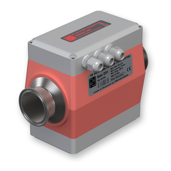
502 010 05 1 General information. Introduction The PD 340 Flow Transmitter is a precision meter for the volumetric measurement of liq- uids that are electrically conducting. The rugged construction of the transmitter makes it suitable for installations where solid par- ticulates make up part of the liquid for measurement. -
Page 6: Construction
502 010 05 Construction The PD 340 Flow Transmitter consists of three parts: • Meterhead • Electronic module • Terminal box The electronic module and the terminal box are the same for all sizes of transmitter. The Meterhead consists of a stainless metering pipe with clamp connections. Two magnet coils are mounted external to the metering pipe. - Page 7 Control valve/ COUNTER 24 V battery Frequency controller (Pump)/ Instrument Mains supply 24 V DISPLAY FOR Transformer FLOW TRANSMITTER FLOW TEMP. VOL.1 SETP. T.C. VOL.2 FLOW PD 210 PD 210 Figure 1: System diagram Manual Flow Transmitter, PD 340 7/55...
-
Page 8: Operating Principles
(see details in the next section, Reducing the influence of varying flow profiles). Practical tests with the PD 340 confirm that it is not necessary to recalibrate the meter when changing product, such as from water to milk. This would normally be necessary when using magnetic flowmeters that have traditional round measuring chambers. -
Page 9: Reducing The Influence Of Varying Flow Profiles
Measures over The average measurement is achieved in a PD 340 by using a the entire cross square measurement chamber, where each of the two electrodes are section of the designed to measure across the complete cross section of flow. -
Page 10: Linearizing Function
During the flow calibration at the factory, the linearizing curve is calculated and downloaded to the electronic module. For this reason, all new PD 340 Flow Transmitters will hold the data needed by the linearizing function, when they are delivered as complete meters, i.e. -
Page 11: Function Description
The required volume is keyed into a setpoint regis- ter. A digital input on the Flow Transmitter may be used to start the batch control. A digital output, Output2, opens the dosing valve or starts a pump. When the setpoint volume is Manual Flow Transmitter, PD 340 11/55... -
Page 12: Flow Control
Error free measurement signal. The output signal is ON if no error is present. • The output may be controlled directly via P-NET. (See configuration of function selector Code2) Further details for connecting Output2 can be found in section 5.3.1 Output2. 12/55 Flow Transmitter, PD 340 Manual... -
Page 13: Output3
Fur- thermore the PD 210 display unit may be used to change setpoint values and to perform a complete configuration of the Flow Transmitter (see description in section 3). Manual Flow Transmitter, PD 340 13/55... -
Page 14: Display
502 010 05 3 Display Various options are available for displaying information from the PD 340 Flow Transmitter. The Flow Transmitter may be controlled and supervised via the P-NET interface (requires the extended version), and all data may then be accessed. Another solution is to connect a local PD 210 display unit to the Flow Transmitter. -
Page 15: Changing Register Contents
M3 screw for connections Note: Please observe that the M3 mounting screw holes are only 4 mm. deep. 14.6 Do NOT screw down beyond this length. This may damage the dis- play unit. 127.0 Manual Flow Transmitter, PD 340 15/55... -
Page 16: Flowmeter-Display, Pd 4000/340
Flowmeter-Display, PD 4000/340 The Flowmeter-Display is based on a PD 4000 P-NET Controller and is designed to display data from PD 340 Flow Transmitters. Furthermore it is possible to change data and to select various functions in the Flow Transmitters. -
Page 17: Meter Selection And Installation
This applies to any flow transmitter on the market. How- ever, it is possible to use the PD 340 even at very low flow rates, whilst still obtaining high accuracy. Flow measurement down to 1 % of maximum flow rate for the Flow Transmitter is... -
Page 18: Installation And Care Of Transmitter
Using the transmitter under these condi- tions may cause damage, which will not be covered under the product guarantee. 18/55 Flow Transmitter, PD 340 Manual... - Page 19 The Flow Transmitter supply should always be connected, as heat developed in the elec- tronic module prevents any condensation, which could damage the transmitter. The transmit- ter should therefore be powered up as soon as possible after mounting. Manual Flow Transmitter, PD 340 19/55...
-
Page 20: Electrical Connections
The output is protected with a zener diode and a current-limiting resistor in the same way as the pulse outputs. Furthermore, the output is isolated from the internal elec- tronics by a transformer. The output is not isolated from the power source supplying the transmitter. 20/55 Flow Transmitter, PD 340 Manual... -
Page 21: Digital Output Signals
Counter specification: FLOW TRANSMITTER COUNTER Supply voltage: 20-40 V DC Power consumption: Max. 2.5 W Output 1 Counting frequency: Min. 10 Hz ON-time: Typ. 40 ms Output 2 OFF-time: Min. 60 ms 551 106 01 Manual Flow Transmitter, PD 340 21/55... -
Page 22: Output3
12 V at terminals 17 and 18 in the Flow Transmitter plus the voltage drop across the Min. 12 V Max. 50 V load and cable. The necessary supply voltage must be calculated for max. current, 20 mA. 551 108 01 22/55 Flow Transmitter, PD 340 Manual... - Page 23 FREQUENCY CONTROLLER (PUMP)/ INSTRUMENT Output 1 Output 3 551 110 01 Supplied by an external power supply FLOW TRANSMITTER POWER CONTROL VALVE/ FREQUENCY CONTROLLER (PUMP)/ 24-50 V DC INSTRUMENT Output 3 551 111 01 Manual Flow Transmitter, PD 340 23/55...
-
Page 24: Input Signal
P-NET is standardised internationally (IEC 61158 Type 4). Up to 125 units can be connected to the fieldbus, where a device may be a PD 340 Flow Transmitter, a Flowmeter Display or another P-NET interface module. The P-NET interface is galvanically isolated. The fieldbus cable is a twisted pair cable with shield, and the shield is used as a potential equalizer be- tween the driver/receiver circuits in the nodes connected to the fieldbus. - Page 25 Shielded twisted pair cable with minimum .22 mm² area conduc- tors and characteristic impedance of 100-120 ohm. For example TWINAX IBM part No. 7362211 with 105+/-5 ohm, 51 pF/m. Cable length: Max. 1200 m (EIA RS 485). Manual Flow Transmitter, PD 340 25/55...
-
Page 26: Variable Description
502 010 05 6 Variable description PD 340 Flow Transmitter holds a number of variables and functions, which all may be ac- cessed via P-NET and some via the PD 210 display unit. SoftWire Table The variables in the PD 340 Flow Transmitter are located at logical addresses called Soft- Wire numbers. - Page 27 P-NET SWNo 0: SerialNo PD 210 display: not accessible This register contains a production serial number, which is set by PROCES-DATA and cannot be changed. This serial number is printed on the electronic module. The serial number is used for service purposes and as a 'key' to set the P-NET node ad- dress for the Flow Transmitter.
- Page 28 Temperature > 130 ° C / 266 ° F Overrun, volume counter 2 Overrun, volume counter 1 Input active Flow >> max / metering pipe empty Flow > max Overflow, Output2 Overflow, Output3 No error 28/55 Flow Transmitter, PD 340 Manual...
-
Page 29: Process Variables
10 sec. Reverse flow (relative to the arrow on the meter head) can be set to 0, as well as Flow rates smaller than 0.2% of max. flow can be set to 0 (selected in Code3). Manual Flow Transmitter, PD 340 29/55... - Page 30 Metersize. The Code2 register, digit 4 should be set to 1 in order to select Flow as data for volume counters. Note: Using this kind of temperature compensation will only give the correct result when the liquid is at the fixed temperature. 30/55 Flow Transmitter, PD 340 Manual...
- Page 31 Furthermore it is possible to clear Volume2 by means of Input1 or Batchstart. P-NET SWNo. 17: Setpoint PD 210 display key: SETP. The Setpoint register has several functions depending on the selected options for the PI- regulator and Batch control / Limit switch: Manual Flow Transmitter, PD 340 31/55...
-
Page 32: Configuration And Calibration Parameters
I-component of the regulator is disabled and set to zero. See also the application example Flow control. Please consult the specialist literature on the subject of process control for further informa- tion on how to set the regulator parameters for particular purposes. 32/55 Flow Transmitter, PD 340 Manual... - Page 33 PD 210 display address: E4, Meternumber The meter head serial number may be retrieved from this register. This number is set by PROCES-DATA and is used for service purposes only. The serial number is printed on the side of the Flow Transmitter meter head.
- Page 34 Example : In MeterSize the size of the transmitter is specified to be 20 m /h. On Output2, 1 pulse is required for each 0.01 m (10 litres). Digit 3 in Code1 is set to 2 (2 digits after the decimal point). 34/55 Flow Transmitter, PD 340 Manual...
- Page 35 Temp Pulse output, 0 Available Limit switch Available - 1000 Hz Volume1 3-phase output Error code=0 Volume2 mode 1 3-phase output mode 2 Sign for 3-phase output Instantflow Instantflow TEST Instantflow Output3 mode 3 Manual Flow Transmitter, PD 340 35/55...
- Page 36 When set to measure in one direction only, flow in the opposite direction to the arrow is ignored. 36/55 Flow Transmitter, PD 340 Manual...
-
Page 37: Standard Settings
0.1 litre/pulse (C51, C63 and C 76) Extended version : Output2: 1 litre/pulse (C 25 and C 38) 10 litre/pulse (C 51, C 63 and C 76) Output3: 20 mA at max flow rate Manual Flow Transmitter, PD 340 37/55... -
Page 38: 3-Phase Output Signals
502 010 05 7 3-phase output signals The PD 340 Flow Transmitter - extended version, can be configured to drive 3-phased out- put signals. The configuration makes the Flow Transmitter act like a mechanical flowmeter. The 3-phase output signals may be used in three different modes. Below is a brief overview prior to more comprehensive explanations later in this section: •... -
Page 39: 3-Phase Counter Without Separate Error Signal
See the first of the signal diagrams below. In the second diagram, a backward flow alters the sequence of the two pulse signals. Apart from the phase sequence, the function- ality for backward flow is the same as for forward flow. Manual Flow Transmitter, PD 340 39/55... -
Page 40: Counter With Up/Down Signal And Separate Error Signal
The flow direction is indicated by the up/down signal and the pulse frequency indicates the flow rate. An error in the Flow Transmitter will open all 3 output signals (high-impedance state). See the signal diagram below. 40/55 Flow Transmitter, PD 340 Manual... - Page 41 X * 8 * * 0 0 0, where X can have the mode values: 6, 7 and 8. The * indicates that these digits should be configured according to the actual application and working conditions for the Flow Transmitter. Manual Flow Transmitter, PD 340 41/55...
-
Page 42: Applications
PD 210 551 114 01 A centrifugal pump, a PD 340 Flow Transmitter, and a modulating valve with an I/P con- verter can form an accurate FLOW CONTROL SYSTEM. Such a system is more accurate, and also normally less expensive than systems using a positive pump with variable speed. - Page 43 The min. and max. flow rate, the flow/pressure curves of the pump, and the pressure drop in the pipe work at the specified flow rate. It is normally recom- mended to ask the supplier of the modulating valve to select the size. Manual Flow Transmitter, PD 340 43/55...
-
Page 44: Batch Control Using The Pd 210 Display
The requested volume is keyed into "SETPOINT" on the PD 210. Input1 on the PD 340 is used to start the batch control. Output2 controls the dosing valve or pump. The Volume2 counter shows the dosed volume. - Page 45 Input 1 Input 1 24 v Output 3 4-20 mA Display PD 210 PD 210 Output 1 24-32 V Relay 24 V / 50 mA Output 2 Power 24 V AC/DC Input 551 119 01 Manual Flow Transmitter, PD 340 45/55...
-
Page 46: Fault Finding
9 Fault finding Error detection The PD 340 Flow Transmitter is equipped with a comprehensive self testing system, which is able to indicate faults arising from improper use of the transmitter, or faults arising whilst the transmitter is in use. -
Page 47: Flow Transmitter Without Display Unit
Check that the flow direction is correct. If the transmitter gives a false read-out • Check if there is any air in the liquid. • Check that the conductivity of the liquid lies within the specified range. Manual Flow Transmitter, PD 340 47/55... -
Page 48: List Of Spare Parts
502 010 05 10 List of spare parts The following spare parts are available for PD 340. Meterhead without electronic module and terminal box: • PD 340 C 25 • PD 340 C 38 • PD 340 C 51 •... -
Page 49: Specifications
The transmitter should always have the supply connected to prevent condensation in the electronics. Power supply AC (50/60 Hz) or DC: nom. 24.0 V min. 20.0 V max. 28.0 V Current at power up: max. 650 mA Manual Flow Transmitter, PD 340 49/55... -
Page 50: Liquid
Approvals Compliance with EMC-directive no.: 89/336/ECC Generic standards for emission: Residential, commercial and light industry DS/EN 61000-6-3 Industry DS/EN 61000-6-4 Generic standards for immunity: Residential, commercial and light industry DS/EN 61000-6-1 Industry DS/EN 61000-6-2 50/55 Flow Transmitter, PD 340 Manual... -
Page 51: Dimensions
11.9 Material Electrodes: Stainless steel AISI 316. Metering pipe: Stainless steel AISI 316. Coating inside metering pipe: FEP Teflon. Housing: PPO Noryle. 11.10 Connections Clamp pipe coupling DS/ISO 2852. Manual Flow Transmitter, PD 340 51/55... -
Page 52: Memory Types
12.1 Memory types The PD 340 stores data in different types of memory depending on the value of a control variable following a reset or a power failure, and the state of the write protection. Some variables are stored in both non-volatile memory and in volatile memory. The state of the module's Program enable switch determines whether the contents are changed in both types of memory or only in the volatile type. - Page 53 502 010 05 13 Appendix 2 Figure 7: Software diagram Manual Flow Transmitter, PD 340 53/55...
-
Page 54: Index
Liquid, 50 DeviceType, 26, 27 Local display, 14 Dimensions, 51 Display, 14 Display resolution, 34 Manual operation, 31 Display unit, 13, 14, 24, 31, 34, 35, 36, 46 Material, 51 Dosing, 44 Measuring range, 17 54/55 Flow Transmitter, PD 340 Manual... - Page 55 Regulator, 32 Variable description, 26 Regulator function, 33 Vibration, 19, 51 Reset, 28 Volume counter, 11, 31 Resolution, 35 Volume1, 26, 31, 35 Reverse flow, 29, 32 Volume2, 26, 31, 35 Volumetric unit, 32 Manual Flow Transmitter, PD 340 55/55...
Need help?
Do you have a question about the PD 340 and is the answer not in the manual?
Questions and answers