Table of Contents
Advertisement
Quick Links
Advertisement
Table of Contents

Related Manuals for HPRT FC53-Li


Summary of Contents for HPRT FC53-Li
- Page 1 Thermal Transfer Overprinter FC53-Li/FC53-Lc/FC53-Ri/FC53-Rc User Manual...
-
Page 2: Table Of Contents
Content SAFETY INSTRUCTIONS............................5 1. PRODUCT INTRODUCTION..........................8 1.1 Features..............................8 1.2 Appearance and Components........................9 1.3 Type of Printer............................11 1.4 Device Setting File..........................12 1.5 Retrieving and Downloading Jobs......................13 1.6 LED Indicator Definition......................... 16 1.7 Specifications............................17 2. INTERFACE................................ 20 2.1 Type of Screen............................20 2.1.1 Home Screen........................... - Page 3 5. MAINTENANCE..............................70 5.1 Clean and Maintenance......................... 70 5.2 Maintenance Plan..........................70 5.2.1 Quick/Regular Checks........................70 5.2.2 Regular Monthly Checks......................... 71 5.2.3 Maintaining the Print Head......................71 5.3 Cleaning the Print Head......................... 72 5.4 Replace Print Head..........................73 5.4.1 Remove the Damaged Print Head....................73 6.
-
Page 4: Safety Instructions
FC53-Li/FC53-Lc/FC53-Ri/FC53-Rc User Manual Safety Instructions Before operating and using the printer, please carefully read the following safety regulations in order to prevent any hazard or material damage. 1. Safety warning Warning - This must be complied with in order to avoid any damage to the human body and the equipment. - Page 5 FC53-Li/FC53-Lc/FC53-Ri/FC53-Rc User Manual 3) Use the original accessories only and do not try to disassemble, repair or remodel it by yourself. • Call your dealer when you need these services. • Do not touch the blade of auto cutter. 4) Do not let water or other foreign objects drop into the printer.
- Page 6 FC53-Li/FC53-Lc/FC53-Ri/FC53-Rc User Manual 4. WEEE (Waste Electrical and Electric Equipment) This mark shown on the product or its literature indicates that the corresponding item should not be discarded at the end of its working life with others household waste. To prevent possible harm to the environment or human health from uncontrolled waste disposal, please separate marked items from other types of waste and recycle them responsibly to promote the sustained reuse of material resources.
-
Page 7: Product Introduction
FC53-Li/FC53-Lc/FC53-Ri/FC53-Rc User Manual 1. Product Introduction 1.1 Features This product has the following characteristics: • Separate module design for coding mechanism and control panel Coder: All metal structure, strong and durable Control Panel: Color touch screen panel with friendly UI interface •... -
Page 8: Appearance And Components
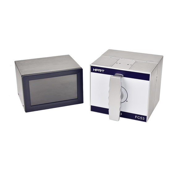
FC53-Li/FC53-Lc/FC53-Ri/FC53-Rc User Manual 1.2 Appearance and Components FC53-Li/FC53-Lc/FC53-Ri/FC53-Rc consists of a printing device and a control device (equipped with an operation interface control panel). Controller user interface Printer Ribbon cassette Print head module Rev.2.0... - Page 9 FC53-Li/FC53-Lc/FC53-Ri/FC53-Rc User Manual Main Components The main components of FC53-Li/FC53-Lc/FC53-Ri/FC53-Rc are as follows: Printer body, including drive system and thermal transfer print head. Ribbon cassette of printer body, with ribbon supply shaft and old ribbon reel. Controller device including main operation printed circuit board and user interface.
-
Page 10: Type Of Printer
This model is used with intermittent packaging equipment and will print with the materials fixed. The FC53-Li/FC53-Ri printer has a print area of 53 mm x 75 mm in this mode and a print speed of 40 to 600 mm / s. -
Page 11: Device Setting File
settings file. After the job is downloaded to FC53-Li/FC53-Lc/FC53-Ri/FC53-Rc, the data is stored as an .xml file and contains a .prt file and a .param file. The job name is usually the same as the product code, and can be different if necessary. -
Page 12: Retrieving And Downloading Jobs
Once the required image is loaded on the USB flash drive, the relevant image can be downloaded to the local database of FC53-Li/FC53-Lc/FC53-Ri/FC53-Rc. 1. Insert the pre-loaded USB flash drive into the USB connector on the back of the controller. - Page 13 FC53-Li/FC53-Lc/FC53-Ri/FC53-Rc User Manual 2. In the Menu screen, select File Management, and then select Copy File. Rev.2.0...
- Page 14 FC53-Li/FC53-Lc/FC53-Ri/FC53-Rc User Manual 3. Select "Copy the file from USB drive". Rev.2.0...
-
Page 15: Led Indicator Definition
FC53-Li/FC53-Lc/FC53-Ri/FC53-Rc User Manual 1.6 LED Indicator Definition LED status and color Printer status Possible Causes Light off Shutdown or without power supply Shutdown or without power supply Green light stays on Functional and in standby mode Functional and in standby mode... -
Page 16: Specifications
FC53-Li/FC53-Lc/FC53-Ri/FC53-Rc User Manual 1.7 Specifications (1/3) Items Specifications FC53-Li (Left, Intermittent),FC53-Lc (Left, Continuous), FC53-Ri (Right, Intermittent), Model Name FC53-Rc (Right, Continuous) Structure All-metal structure Print Mode Thermal transfer printing Print Width (Max.) 53 mm (300dpi) Print Area 53mm*75mm (Intermittent), 53mm*100mm (Continuous) - Page 17 FC53-Li/FC53-Lc/FC53-Ri/FC53-Rc User Manual (2/3) Items Specifications Bitmap fonts: 6, 8, 10, 12, 14, 18, 24, 30, 16x26 and OCR A & B Bitmap fonts: 90 °, 180 °, 270 ° can be rotated, single characters can be rotated Built-in Font 90 °, 180 °, 270 °...
- Page 18 FC53-Li/FC53-Lc/FC53-Ri/FC53-Rc User Manual (3/3) Items Specifications USB Interface STD, 1 port, type B connector, USB device 2.0 USB Main STD, 1USB disk connection port Interface USB Host 2.0, automatic detection and setting of connections STD 1 port, female D-SUB 9-pin connector...
-
Page 19: Interface
FC53-Li/FC53-Lc/FC53-Ri/FC53-Rc User Manual 2. Interface 2.1 Type of Screen The FC53-Li/FC53-Lc/FC53-Ri/FC53-Rc user interface supports a variety of screen types. The screen interface is generally divided into a central home screen and option buttons arranged vertically on both sides. The rightmost column is the "Pause" key and the "Start" key. - Page 20 FC53-Li/FC53-Lc/FC53-Ri/FC53-Rc User Manual Screen Type Description: Type of Screen Description Home screen Home screen where the user first started To navigate between different menu options or screen Menu screen types Diagnostic screen To display real-time dynamic data Fault and warning...
-
Page 21: Home Screen
FC53-Li/FC53-Lc/FC53-Ri/FC53-Rc User Manual 2.1.1 Home Screen The home screen is the screen from which the user started to operate. This screen can be the “Ready” screen or the “Printing” screen. Various menus are accessible through the screens of both versions. -
Page 22: Menu Screen
FC53-Li/FC53-Lc/FC53-Ri/FC53-Rc User Manual 2.1.2 Menu Screen Navigate the menu by selecting the desired option button. When you enter a menu, the top item in the list is highlighted. You can select the green back arrow at the bottom left of the screen to return to the previous screen. -
Page 23: Diagnostic Screen
FC53-Li/FC53-Lc/FC53-Ri/FC53-Rc User Manual 2.1.3 Diagnostic Screen The Diagnostic screen displays current status and dynamically changing data to help troubleshoot problems. The information displayed is read-only and cannot be changed. This screen allows you to access the following information: -Input status (current substrate speed) -
Page 24: Fault And Warning Screen
FC53-Li/FC53-Lc/FC53-Ri/FC53-Rc User Manual 2.1.4 Fault and Warning Screen These screens inform you of current or potential problems. A description of the problem appears on the screen. When a fault occurs, a warning message is displayed on the home screen. For example:... -
Page 25: Operation
FC53-Li/FC53-Lc/FC53-Ri/FC53-Rc User Manual 3. Operation 3.1 Turn On the Printer 1. Press the power button on the back of the controller to turn on the controller. After powering on, the printer performs a self-test. 2. The controller home screen displays Ready. Press the "Start" key to start printing. -
Page 26: Stop The Printer
FC53-Li/FC53-Lc/FC53-Ri/FC53-Rc User Manual 3.2 Stop the Printer Press the "Pause" key to stop the printer. Rev.2.0... -
Page 27: Print Adjustment Screen
FC53-Li/FC53-Lc/FC53-Ri/FC53-Rc User Manual 3.3 Print Adjustment Screen Select "Print Adjustment" on the main screen to adjust the print darkness and print position. Rev.2.0... -
Page 28: Remove The Ribbon Cassette
FC53-Li/FC53-Lc/FC53-Ri/FC53-Rc User Manual 3.4 Remove the Ribbon Cassette 1. Rotate the locking lever on the cassette to the open position. ( ) 2. Use the handle to remove the ribbon cassette. 3. Remove the waste ribbon from the ribbon cassette. -
Page 29: Load Or Replace The Ribbon
FC53-Li/FC53-Lc/FC53-Ri/FC53-Rc User Manual 3.5 Load or Replace the Ribbon 3.5.1 Remove Waste Ribbon from the Waste Take-up Core 1. Pull the waste ribbon up using the tray located under the waste ribbon. 2. Push the tray back to its original position. -
Page 30: Load A New Ribbon
FC53-Li/FC53-Lc/FC53-Ri/FC53-Rc User Manual 3.5.2 Load a New Ribbon 1. Load the new ribbon in accordance with the ribbon loading instruction label (The label is attached to the ribbon cassette). 2. Pull out the ribbon and wrap it around the waste take-up core as indicated 3. -
Page 31: Reconnect A Broken Ribbon
FC53-Li/FC53-Lc/FC53-Ri/FC53-Rc User Manual 3.6.1 Reconnect a Broken Ribbon When a ribbon break occurs, the following steps should be performed: 1. Do not knot to reconnect the ribbon. 2. Wind the remaining waste ribbon around the waste take-up core. 3. Pull out some unused ribbon from the ribbon supply and wind it around the waste ribbon reel. -
Page 32: Replace The Ribbon Cassette
4. When the ribbon cassette returns to its original position and the key switch is turned to READY ( I ) , the FC53-Li/FC53-Lc/FC53-Ri/FC53-Rc will automatically drive the print head to remove all creases and calibrate the ribbon feed sensor. -
Page 33: Printing Principle
The heat of the printing point will melt the ink, and the pressure between the print head and the substrate will transfer the ink to the substrate. FC53-Li/FC53-Lc/FC53-Ri/FC53-Rc equipment uses the principle of stepper motor to drive the print head / brake movement and ribbon feeding. -
Page 34: Working Principle
The FC53-Li/FC53-Ri intermittent printer uses a thermal print head and thermal ink ribbon to print information onto the material held against a flat print platen. -
Page 35: Printer Configuration
FC53-Li/FC53-Lc/FC53-Ri/FC53-Rc User Manual 4. Printer Configuration 4.1 Access Menu Select "Menu" on the home screen. The main menu screen is displayed. The following options are accessible as needed: Rev.2.0... -
Page 36: Menu Structure
FC53-Li/FC53-Lc/FC53-Ri/FC53-Rc User Manual 4.2 Menu Structure Edit Print Button Stop Button Clear Database Fault&Warning Menu Function Item (Home) screen) Select Task Count Information Consumables Print History Version Information Print Darkness Print Horizontal Offset Adjustment Vertical Offset Task Search Rotation Package Length... - Page 37 FC53-Li/FC53-Lc/FC53-Ri/FC53-Rc User Manual Print Function Print Setting Print Quality Device Setting Setting Print Position Service Ribbon Version Log Record Information Input Status Warning Fault Lamp Diagnosis Temperature Print Head Diagnosis Ribbon Test Internal Manual Control Ribbon Test Menu Copy File...
-
Page 38: Setting Menu
FC53-Li/FC53-Lc/FC53-Ri/FC53-Rc User Manual 4.3 Setting Menu 1. Select "Setting" on the menu screen. 2. Enter the device setting. Note: Most of the above settings should be configured immediately after installation. Other settings (such as print darkness) may need to be adjusted periodically. -
Page 39: Device Setting
2) The minimum printing speed is the lower limit of the substrate speed during printing. The setting range is 40-200mm/s, and the setting accuracy is 1mm/s. FC53-Li/FC53-Ri Intermittent Printer: You can set print speed, mirror mode and ribbon saving mode. - Page 40 FC53-Li/FC53-Lc/FC53-Ri/FC53-Rc User Manual 3) Set the specified task date: Home-> Click " "-> Enter "Template Editor"-> Click "Properties"-> Edit "Time Selection"-> Click "Finish" Rev.2.0...
- Page 41 Missing print operation setting: continue / discard Ribbon advance distance: range 0.5 ~ 10.0 mm FC53-Li/FC53-Ri Intermittent Printer: You can set defibrillation time, print delay, missing print threshold, missing print operation, and ribbon advance distance. the setting range of defibrillation time and print delay is 0-5000ms.
- Page 42 Print darkness adjustment: minimum = -25%; maximum = 25% Contrast 4: 60% ~ 99% Contrast 5: 50% ~ 140% TPH press down distance: 5mm ~ 50mm TPH raised distance: 0.5mm ~ 10mm FC53-Li/FC53-Ri Intermittent Printer: You can set and adjust the print darkness, and set the contrast. Rev.2.0...
- Page 43 FC53-Li/FC53-Lc/FC53-Ri/FC53-Rc User Manual Printing Position: You can set horizontal offset, maximum offset range, minimum offset range, and vertical offset. Note: Horizontal offset setting: minimum = 0 mm; maximum = 50 mm Maximum / minimum offset range setting: minimum = -5mm; maximum = 5mm Vertical offset setting: minimum = 0 mm;...
- Page 44 FC53-Li/FC53-Lc/FC53-Ri/FC53-Rc User Manual Ribbon Monitor: You can set the detection of insufficient ribbon, the threshold and the operation. Note: Insufficient ribbon detection: Yes/No. Insufficient ribbon threshold setting: minimum = 10 meters; maximum = 400 meters Insufficient ribbon operation: Continue/discard ...
-
Page 45: Diagnosis
FC53-Li/FC53-Lc/FC53-Ri/FC53-Rc User Manual 4.4 Diagnosis Select "Diagnosis" on the menu screen to view various information about the status of the printer. Diagnosis 4.4.1 Select "Diagnosis" to query the input status, temperature, ribbon, and internal information. Input status: Display the current substrate speed. - Page 46 FC53-Li/FC53-Lc/FC53-Ri/FC53-Rc User Manual Ribbon: Display the diameter of the currently supplied ribbon and rewinding ribbon. Internal: Display the position of the tension controller, the status of the ribbon cassette switch, the number of connection errors between the controller and printer, the voltage of the print head and the resistance of the print head.
-
Page 47: Manual Control
FC53-Li/FC53-Lc/FC53-Ri/FC53-Rc User Manual 4.4.2 Manual Control Select "Manual Control" to query information about ribbon test and TPH test. Ribbon Test: You can choose to start or stop the ribbon feed. The images selected for the print head test include ASCII code, self-test page, slash, black block, density test and barcode. -
Page 48: Tph Test
FC53-Li/FC53-Lc/FC53-Ri/FC53-Rc User Manual 4.4.3 TPH Test Select “ Diagnosis”---"TPH Test", the following dialog box appears, if you need to detect, click "√". 4.5 Service Select "Service" on the menu screen to set the upgrade from a USB flash drive. Note: After clicking to upgrade from a USB flash drive, search for all the upgrade files in the .upd file format on the USB flash drive and select any file (different from the current... -
Page 49: Version Information
FC53-Li/FC53-Lc/FC53-Ri/FC53-Rc User Manual 4.6 Version Information Select "Version" on the menu screen to view the current hardware and software version. Rev.2.0... -
Page 50: File Operation
FC53-Li/FC53-Lc/FC53-Ri/FC53-Rc User Manual 4.7 File Operation Select "File Operation" on the menu screen, you can access the following options: copy file, delete file, file statistics, clear print database, copy the log to the USB drive and pull error log. Copy File: You can copy files to the USB drive or copy files from the USB drive to the printer system. - Page 51 FC53-Li/FC53-Lc/FC53-Ri/FC53-Rc User Manual Delete File: You can choose different types of files to delete. Clear print database: delete all files in the database. Rev.2.0...
- Page 52 FC53-Li/FC53-Lc/FC53-Ri/FC53-Rc User Manual File Statistics: You can view the current total storage capacity and available storage capacity. Rev.2.0...
-
Page 53: Admin Mode
FC53-Li/FC53-Lc/FC53-Ri/FC53-Rc User Manual 4.8 Admin mode Select "Administrator Mode" on the menu screen and enter the password (the default password is 123456) to enter the administrator mode. After entering the administrator mode, according to user requirements, click the orange button on the right side of the page (as shown below) to change the password. - Page 54 FC53-Li/FC53-Lc/FC53-Ri/FC53-Rc User Manual In "Administrator Mode", you can access the following options: synchronizer setting, ribbon setting, system clock adjustment, restore factory setting, IP setting. ● Synchronizer Setting(Only support continuous printers ): You can set the FC53-Lc/FC53-Rc type, direction, resolution, and diameter of the synchronizer.
- Page 55 FC53-Li/FC53-Lc/FC53-Ri/FC53-Rc User Manual Ribbon Setting: You can set the ribbon model, ribbon width, ribbon length, and ribbon thickness. ● System Clock Adjustment: You can set the date and time of the device's internal clock. Rev.2.0...
- Page 56 FC53-Li/FC53-Lc/FC53-Ri/FC53-Rc User Manual Rev.2.0...
- Page 57 FC53-Li/FC53-Lc/FC53-Ri/FC53-Rc User Manual Restore Factory Setting: Click “Restore the factory setting”, a pop-up dialog box “Whether to clear the local cache” is displayed. Click “√” to set successfully. Rev.2.0...
- Page 58 FC53-Li/FC53-Lc/FC53-Ri/FC53-Rc User Manual IP Setting Click "DHCP", the system will automatically read the IP information; if you click "Static IP", the user will set the IP address and other information according to the network environment. Rev.2.0...
- Page 59 FC53-Li/FC53-Lc/FC53-Ri/FC53-Rc User Manual Pamel Upgrade:You can upgrade the pamel. Extra Function:You can perform the “Import TPH_Extension” function. System Upgrade:You can upgrade the system. Rev.2.0...
-
Page 60: Select Task
FC53-Li/FC53-Lc/FC53-Ri/FC53-Rc User Manual 4.9 Select Task 1. Choose “Select Task” on the home screen. 2. Select the file you want to print. Rev.2.0... -
Page 61: Information
FC53-Li/FC53-Lc/FC53-Ri/FC53-Rc User Manual 3. Select "√" to set the file as the default job. 4.10 Information 1. Choose “Information” on the home screen. Rev.2.0... - Page 62 FC53-Li/FC53-Lc/FC53-Ri/FC53-Rc User Manual 2. Enter the "Information" screen to query the count, material usage, print history and task info. Count: You can view information such as normal print qty, missing print qty, and give up print qty. Rev.2.0...
- Page 63 FC53-Li/FC53-Lc/FC53-Ri/FC53-Rc User Manual Consumables consumption: You can check the remaining ribbon, the remaining printing, the remaining time of the ribbon, TPH print length, and total print length. Print history: Query the print history. Rev.2.0...
-
Page 64: Print Adjustment
FC53-Li/FC53-Lc/FC53-Ri/FC53-Rc User Manual Task Info: Query the editor version. 4.11 Print Adjustment 1. Choose “Print Adjustment” on the home screen. Rev.2.0... - Page 65 FC53-Li/FC53-Lc/FC53-Ri/FC53-Rc User Manual 2. Enter the "Print Adjustment" screen, you can adjust the print darkness, print position and package length. Print Darkness: You can set the print darkness, and the selection range is 80% -125%. Print Darkness Print Darkness...
- Page 66 FC53-Li/FC53-Lc/FC53-Ri/FC53-Rc User Manual Vertical Offset: The vertical offset distance can be set, and the selection range is 0- 600mm (continuous printerFC53-Lc/FC53-Rc ), 0-750mm(for intermittent printer FC53- Li/FC53-Ri). Rev.2.0...
- Page 67 FC53-Li/FC53-Lc/FC53-Ri/FC53-Rc User Manual Horizontal Offset: You can set the horizontal offset distance, the selection range is 0- 50mm. Print Rotation: 0 ° / 90 ° / 180 ° / 270 ° can be set. Rev.2.0...
- Page 68 FC53-Li/FC53-Lc/FC53-Ri/FC53-Rc User Manual Package Length: The package length can be set, and the selection range is 30 mm-1600 Rev.2.0...
-
Page 69: Maintenance
FC53-Li/FC53-Lc/FC53-Ri/FC53-Rc User Manual 5. Maintenance 5.1 Clean and Maintenance To ensure the normal operation of FC53-Li/FC53-Lc/FC53-Ri/FC53-Rc, the entire unit should be cleaned regularly. Special attention should be paid to the inside of the printer body, especially if food residues are able to fall into the printer unit. -
Page 70: Regular Monthly Checks
FC53-Li/FC53-Lc/FC53-Ri/FC53-Rc User Manual Check for abrasion or internal debris. 5.2.2 Regular Monthly Checks Check the condition of the peel roller: Remove the roller, and then check if there is any wear inside. Replace if necessary. Check the condition of the ribbon guide rollers: Check whether the bearing is smooth. -
Page 71: Cleaning The Print Head
To minimize the wear of the print head, the smallest air pressure is usually used to provide acceptable print quality. For the particular FC53-Li/FC53-Lc/FC53-Ri/FC53-Rc used, never exceed the recommended maximum air pressure. Use the minimum darkness setting that provides the required print quality. -
Page 72: Replace Print Head
FC53-Li/FC53-Lc/FC53-Ri/FC53-Rc User Manual 5.4 Replace Print Head 5.4.1 Remove the Damaged Print Head 1. Remove the 3*6mm screw. 2. Remove the two screws sized 3*6mm at the bottom. Rev.2.0... -
Page 73: Interface Function Definition/ Signal Function Definition
FC53-Li/FC53-Lc/FC53-Ri/FC53-Rc User Manual 6. Interface Function Definition/ Signal Function Definition 6.1 Controller Interfaces ① Interface Type 1. USB-B type interface 2. RJ-45 Ethernet interface 3. USB-A type interface 4. RS-232 DB9 serial communication interface 5. External input / output DB15 control connector interface 6. - Page 74 FC53-Li/FC53-Lc/FC53-Ri/FC53-Rc User Manual DB15 Pin Signal Definition Definition Type DC +24V POWER “Start Print” signal input, provided by PNP sensor INPUT (proximity switch) or + 24V switch; GND (0V working ground of the system); POWER User can customize digital input 1 provided by PNP INPUT sensor (proximity switch) or + 24V switch;...
-
Page 75: Printer Interfaces
FC53-Li/FC53-Lc/FC53-Ri/FC53-Rc User Manual 6.2 Printer Interfaces ① Port Function 1. DC+24V connection port, connect the controller through power cable 2. Rotary encoder DB9 input port 3. Waterproof RJ-45 10M/100M Ethernet port with 100Mbps transmission bandwidth 4. TTO print air inlet 5. -
Page 76: Appendix Platen Roller Technical Index
FC53-Li/FC53-Lc/FC53-Ri/FC53-Rc User Manual Appendix Platen Roller Technical Index There are three main technical requirements for platen rollers: 1. Material requirements: aluminum alloy + KE-941 black 2. Technical requirements: 1) Need to be ground 2) End face is flat 3) Without beveling C0.2, deburring 4) The dimension with * must be controlled 5) On-axis hardness: 47°...
Need help?
Do you have a question about the FC53-Li and is the answer not in the manual?
Questions and answers