
Related Manuals for ABB Sensyflow FMT200-D


Summary of Contents for ABB Sensyflow FMT200-D
- Page 1 Operating Instruction Thermal Mass Flowmeter 42/14-37-EN Sensyflow FMT200-D for biogas and compressed air applications...
- Page 2 Fax: +49 621 381 931-29031 automation.service@de.abb.com © Copyright 2010 by ABB Automation Products GmbH Subject to changes without notice This document is protected by copyright. It assists the user in safe and efficient operation of the device. The contents of this document, whether whole or in part, may not be copied or reproduced without prior approval by the copyright holder.
-
Page 3: Table Of Contents
Recommended steadying lengths according to DIN EN ISO 5167-1 ............13 Verifying the conditions ..........................14 Selecting the installation site ........................14 Installing the flowmeter sensor and pipe components .................15 Weld-on adapter for Sensyflow FMT200-D....................16 Electrical connections ..........................18 Commissioning ............................19 Checking the installation ..........................19 Connecting the power supply........................19... -
Page 4: Safety
These devices are not permitted for use in zone 0 or zone 1 potentially explosive atmospheres. The device is designed for use exclusively within the values stated on the name plate and in the technical specifications (see the section titled "Specifications"). Sensyflow FMT200-D 42/14-37-EN... -
Page 5: General Information
Defective gaskets or O-rings must be removed from use and must be replaced as a matter of urgency. • The subsequent mechanical labeling or machining of pipe components and flowmeter sensors can result in damage and is prohibited. Exception: Cutting to length and welding onto the pipeline in the case of weld-on adapters. 42/14-37-EN Sensyflow FMT200-D... -
Page 6: Installing / Disassembling Pipe Components
Prior to using corrosive and abrasive materials for measurement purposes, the operator must check the level of resistance of all parts coming into contact with the materials to be measured. ABB Automation Products GmbH will gladly support you in selecting the materials, but cannot accept any liability in doing so. -
Page 7: Plates And Symbols
Failure to observe this safety information may result in damage to or destruction of the product and/or other system components. IMPORTANT (NOTICE) This symbol indicates operator tips, particularly useful information, or important information about the product or its further uses. It does not indicate a dangerous or damaging situation. 42/14-37-EN Sensyflow FMT200-D... -
Page 8: Name Plates
Safety Name plates Sensyflow FMT200-D Hilfsenergie 24 V AC, 48-62 Hz/24 V DC, 15 W LR 113631-1 Made in Germany ABB Automation, 63755 Alzenau F-Nr.: G01037 Fig. 1 1 Device manufacturer 5 Permissible supply power, frequency 2 Labeling, e.g., for CSA approval... -
Page 9: Returning Devices
Please Please contact Customer Center Service acc. to page 2 for nearest service location. Integrated management system ABB Automation Products GmbH operates an integrated management system, consisting of: • Quality management system to ISO 9001:2008 •... -
Page 10: Disposal
If it is not possible to dispose of old equipment properly, ABB Service can accept and dispose of returns for a fee. 1.10.2 RoHS Directive 2002/95/EC With the Electrical and Electronic Equipment Act (ElektroG) in Germany, the European Directives 2002/96/EC (WEEE) and 2002/95/EC (RoHS) are translated into national law. -
Page 11: Design And Function
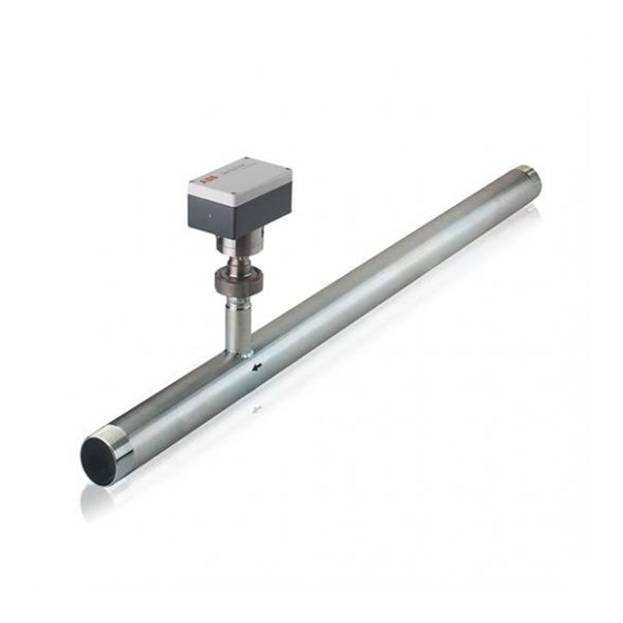
Pipe component with flange connection Weld-on adapter Fig. 2 Flowmeter sensor Sensyflow FMT200-D Lock nut The mass flowmeter works according to the thermal measuring principle of a hot-film anemometer. Heat is drawn out of a heated body by a gas circulating around it. This flow- dependent cooling is utilized as a measuring effect. -
Page 12: Pipe Components
In addition, a flow-linearized analog signal of 0/4…20 mA (electrically isolated) is directly provided. No special supply/evaluation device is required. The flowmeter sensor is installed in the pipe component as a plug-in unit with a centering pin in a defined manner. See chapter 8 Specifications. Sensyflow FMT200-D 42/14-37-EN... -
Page 13: Mounting
3 x D. The reduction of the For gases with extremely low density (hydrogen, helium) the stead- minimum inlet run length, however, will impact on the achievable ying lengths must be doubled. accuracy. Change from one to two columns 42/14-37-EN Sensyflow FMT200-D... -
Page 14: Verifying The Conditions
Components affecting the flow like valves or shut-off devices should be installed on the outlet side, i. e. downstream of the measuring point. • When using a weld-on adapter to install the flowmeter sensor, observe chapter 9.2. Make sure that all installed devices can be accessed easily. Sensyflow FMT200-D 42/14-37-EN... -
Page 15: Installing The Flowmeter Sensor And Pipe Components
When using flange-type pipe components all flange screws must be installed properly. • Connecting threads are to be connected with the pipelines of the system using suitable sealant. All screw connections are to be checked for tightness. 42/14-37-EN Sensyflow FMT200-D... -
Page 16: Weld-On Adapter For Sensyflow Fmt200-D
Mounting Weld-on adapter for Sensyflow FMT200-D Length of weld-on adapter at delivery: L = 117 mm (4.6"). For outer pipe diameter 100 ... 150 mm (4 ... 6“) Prior to welding the weld-on adapter must be shortened to the appropriate length so that it has the length L after welding. This results in a measuring position in the middle of the pipeline. - Page 17 Mounting Centering pin Flow direction G01036 Fig. 5: Weld-on adapter mounted to pipeline, centering pin right (outflow side) 42/14-37-EN Sensyflow FMT200-D...
-
Page 18: Electrical Connections
If the shielding is routed directly into the housing, it will not have the desired effect (shielding effect will be lost). 5. Attach the connection head cover and screw it tight. 6. Check that the gasket is seated properly. Sensyflow FMT200-D 42/14-37-EN... -
Page 19: Commissioning
This can result in severe injuries or death. Only switch on the supply power when the housing cover is closed. Switching on the supply power Once the supply power has been switched on, the device starts to run automatically. 42/14-37-EN Sensyflow FMT200-D... -
Page 20: Parameterization
0 ... 20 mA Minimum 4 ... 20 mA These settings can be modified using the LC interface and the corresponding configuration software. Other error messages can be read out via the "status" function ("check function", section 6). Sensyflow FMT200-D 42/14-37-EN... -
Page 21: Specifications
< 1 kPa (10 mbar [0.145 psi]) at full scale decreasing quadratically for smaller flow rates Parameterize The output signal of the Sensyflow FMT200-D flowmeter can be Ambient conditions toggled between 0 … 20 mA and 4 … 20 mA. Additionally, a... -
Page 22: Dimensions
R1 1/2“: 48.3 x 3.2 150 (5.91“) 50 (2“) 1080 (42.52“) 810 (31.89“) 53.9 (2.12“) R2“: 60.3 x 3.2 165 (6.50“) 80 (3“) 1600 (62.99“) 1200 (47.24“) 79.9 (3.15“) R3“: 88.9 x 4.5 200 (7.87“) Dimensions in mm (inch) Sensyflow FMT200-D 42/14-37-EN... -
Page 23: Weld-On Adapter For Sensyflow Fmt200-D
Dimensions Weld-on adapter for Sensyflow FMT200-D Rd52 x 1/6” Ø 34 (1,34”) G01022 Flow direction → Fig. 8: Weld-on adapter DIN 11851 with lock nut. Dimensions in mm (inch) Centering pin Length of weld-on adapter at delivery: L = 177 mm (4.6"). -
Page 24: Appendix
3 months). You should also line the box with a layer of union paper. All devices returned to the manufacturer must be accompanied by a completed and signed decontamination certificate (see Appendix). Without this, ABB will not be able to process the return. -
Page 25: Declaration Of Conformity
Appendix 10.4 Declaration of conformity 42/14-37-EN Sensyflow FMT200-D... - Page 26 Appendix Sensyflow FMT200-D 42/14-37-EN...
- Page 27 Appendix 42/14-37-EN Sensyflow FMT200-D...
- Page 28 Radioactive Which substances have come into contact with the device? We hereby state that the devices / components shipped have been cleaned and are free from any dangerous or poisonous substances. Town/city, date Signature and company stamp Sensyflow FMT200-D 42/14-37-EN...
-
Page 29: Index
Installing / Disassembling the flowmeter sensor..6 Verifying the conditions..........14 Installing the flowmeter sensor and pipe components ................15 Warranty ..............6 Integrated management system ........9 Warranty provisions ...........6 Intended use ..............4 Weld-on adapter for Sensyflow FMT200-D ..16, 23 Change from one to two columns 42/14-37-EN Sensyflow FMT200-D... - Page 30 ABB has Sales & Customer Support expertise in over 100 The Company’s policy is one of continuous product countries worldwide. improvement and the right is reserved to modify the information contained herein without notice. www.abb.com/flow Printed in the Fed. Rep. of Germany (09.2010) ©...
Need help?
Do you have a question about the Sensyflow FMT200-D and is the answer not in the manual?
Questions and answers