
Related Manuals for Cloos QINEO NexT


Summary of Contents for Cloos QINEO NexT
- Page 1 OPERATING INSTRUCTIONS QINEO NexT • Master • Premium • AC/DC -En- This is a translation of the original operating instructions. BA QN-NX - 04/20 - Rev.3.41 Keep for future use...
- Page 2 Carl Cloos Schweisstechnik GmbH Carl-Cloos-Strasse 1 35708 Haiger GERMANY Telephone +49 (0)2773 85-0 Telefax +49 (0)2773 85-275 E-mail info@cloos.de www.cloos.de...
- Page 3 CARL CLOOS Schweisstechnik GmbH Carl-Cloos-Strasse 1 35708 Haiger/Germany Tel. +49 (0)2773/85-0 Fax. +49 (0)2773/85-275 mail: info@cloos.de www.cloos.de EU declaration of conformity No. CMM0917QNNX_01 Product description: MIG/MAG welding machine Model name: QINEO NexT, WD Serial number: Refer to the nameplate on the back of the device...
-
Page 5: Table Of Contents
Safety precautions in daily operation .............24 Environmental circumstances ................ 25 Storage ..........................25 Transport ........................26 Qualification of users ..................26 Block 2 Basic information Qineo NexT Power source views ................... 28 Product description ..................30 Transport ......................30 Commissioning ....................30 Shutdown / Recycling .................. - Page 6 CleanStart.......................44 Blow through ......................44 Threading (only in connection with MoTion Equipment) ....44 Wire forward ......................44 Wire backward .....................44 Gas manually ......................44 Start manually .....................45 Off / Re-start ......................45 MAIN - Programming ...................45 Parameters in the operating modes 2-cycle and 4-cycle ....46 Parameters in the operating mode Super-4-cycle .......47 Parameters in operating mode Spot Welding / Interval ....48 MAIN - Programming - Setting ranges ............49...
- Page 7 10.3 Diagnostics - Control ..................82 10.3.1 Diagnostics - Control - Ethernet ..............83 10.3.2 Diagnostics - Control - I / O (inputs and outputs) .......83 10.3.3 Diagnostics VBC module ..................85 10.3.4 Diagnostics - Control - LED ................86 10.3.5 Diagnostics - Control - Tandem ..............87 10.4 Diagnostics - Process control .................87 10.4.1...
- Page 8 Description of the additional functions ..........117 DuoPulse ......................117 CleanStart......................117 QWD ........................117 Functions - System logbook ................ 118 Functions - Diagnostics ................. 118 3.5.1 Diagnostics - Software versions ..............118 3.5.2 Diagnostics - Power unit ................118 3.5.3 Diagnostics - Cooling module ..............
- Page 9 5.10.2 User management and PAK ................ 142 5.11 PC adaptation ....................146 5.12 Options ......................... 146 5.13 Activation code ....................147 5.14 Time ........................147 5.15 Off / Re-start ....................... 147 5.16 Torch remote control ..................147 Block 4 Additional information RC Plus (Remote Control) ................
- Page 10 8.3.1 QWD-M4 ......................183 8.3.2 QWD-P5 / QWD-M5 ..................184 Inserting the welding wire ................185 8.4.1 QWD-M4 ......................185 8.4.2 QWD-P5 / QWD-M5 ..................186 Adjustment of the pressure clamps ............187 Maintenance ....................188 Error list ......................189 Disposal and Recycling ................
-
Page 11: Block 1 Operational Safety
Block 1 Operational Safety... -
Page 12: Foreword
Foreword 1. Foreword Dear customer, You have decided to purchase a CLOOS shielding gas welding machine from the QINEO series. This is a brand-name product which will meet your highest quality requirements. Messrs. CLOOS Schweisstechnik GmbH are a company certified to DIN ISO 9001 and who put great emphasis on development, manufacture and quality of their products. -
Page 13: Safety Symbols In This Document
2. Safety symbols in this document INFO! INFO! Practical tips and other useful information! ATTENTION! ATTENTION! The signal word indicates a hazard without risk of a physical impairment, which, if not avoided, can lead to property damage. CAUTION! CAUTION! Describes a probably dangerous situation which may result in minor injury or damage to property. -
Page 14: Safety Specifications For Mig/Mag Welding Machines
Safety specifications for MIG/MAG welding machines 3. Safety specifications for MIG/MAG welding machines Connection, service and repair works must only be carried out by qualified WARNING! personnel who have the appropriate professional training and sufficient experience and knowledge of the power source and who are able to perform the required works in accordance with the relevant safety specifications. -
Page 15: Application As Directed
3.2 Application as directed The welding machine is exclusively intended for application as directed. The welding machine must only be used for welding processes and working ranges scheduled on the power sign. Every other use is regarded as not directed. The manufacturer is not liable for damages occurred hereof. - Page 16 Safety specifications for MIG/MAG welding machines 3.3.2. High frequency electromagnetic compatibility EMC machine classification in accordance with standard EN 60974-10 (see type plate or the specification of technical data). Class B machines meet the EMC requirements in industrial and residential areas, including residential areas connected to the public low voltage supply network.
- Page 17 3.3.4. Gases and vapours • All metal vapours are harmful to health! CAUTION! • Be careful with alloys which contain lead, cadmium, copper, zinc, nickel, chrome and beryllium. • Chloric cleaning and degreasing agents can lead to the formation of the WARNING! toxic gas phosgene due to the decomposition in the arc (risk of suffoca- tion!).
-
Page 18: Electrical Danger Due To Mains Current And Welding Current
Safety specifications for MIG/MAG welding machines 3.3.6. Noise • Noise may cause permanent damage to your hearing. During welding the admissible noise level might be exceeded under unfavourable conditions. • Please make sure that the admissible maximum values are not exceeded (Security Administrator). - Page 19 Connection to ungrounded networks (e.g. IT networks) or asymmetrically ATTENTION! grounded networks is only permitted with an appropriate isolating transformer Position Designation Colour Phase conductor 1 brown Phase conductor 2 black Phase conductor 3 grey Earth conductor blue Protective conductor green-yellow CAUTION! The terminal voltage of the power source can be up to 113 V DC or 48 V AC !
- Page 20 Safety specifications for MIG/MAG welding machines Depending on the process used, it may happen that there is an addition of the two open circuit voltages between the welding electrodes of two power sources. There is possibly the risk of danger to life if both potentials are touched at the same time, see Figure 3.
- Page 21 The side panels and covers of the QINEO series are earthed by means of ATTENTION! screws and toothed conical spring washers. The conical spring washers guarantee an electro-conductive connection between the side panel/cover and the housing. Please make sure that the conical spring washers are correctly re-installed after a removal and reinstallation of the side panels and cover.
- Page 22 Safety specifications for MIG/MAG welding machines Figure 5. with grounded electronic tools 1 = Welding power source, 2 = Electric tool, 3 = Workpiece 1, 4 = Workpiece 2 The welding current flows via the protective conductors of the two electric CAUTION! tools, if by mistake welding takes place on tool 4 without having changed connections (earth) of the welding current return line from workpiece 3 to...
-
Page 23: Particular Dangers When Mig/Mag Welding
3.5 Particular dangers when MIG/MAG welding In daily welding practice there are particular danger spots for the user because of the power source configuration and the MIG/MAG welding process. WARNING! Keep hands, hair, clothes and tools away from moving parts such as: •... -
Page 24: Safety Precautions In Daily Operation
• Only use the original coolant of the manufacturer if liquid cooled power sources are concerned. • Only the original coolant is suitable for the CLOOS power sources because of its properties such as electric conductivity, antifreeze compound, mate- rial compatibility, protection against corrosion and inflammability. -
Page 25: Environmental Circumstances
If the air entrance ports of the power source are provided with air filter mats, ATTENTION! it should be considered that the duty cycle of the power sources reduces in dependence of the increasing degree of soiling of the air filter mat. The cleaning interval for the air filter mat must be determined as experience shows because the pollution of the filter mat depends on the ambient conditions. -
Page 26: Transport
Only persons who have been trained and instructed on the machines in the QINEO series and who have the required qualifications are permitted to carry out work on CLOOS shielding arc welding machines. The manufacturer is not liable for damage to property or persons caused by INFO! unqualified personnel. -
Page 27: Block 2 Basic Information Qineo Next
Block 2 Basic information Qineo NexT... -
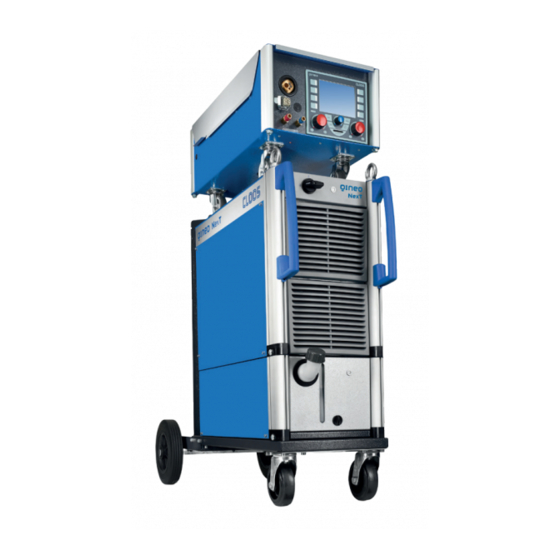
Page 28: Power Source Views
1. Power source views Figure 6. Front view QINEO NexT (left) and QINEO NexT AC (right) Main switch Status LED welding power source Status LED cooling unit Level indicator Coolant filler neck... - Page 29 Mains connection Welding current positive cable Welding current negative cable Coolant return (red) Coolant flow (blue) Coolant drain cock Coolant overflow (under- neath the cooling module) Cooling module lock Figure 7. Rear view QINEO NexT (left) and QINEO NexT AC (right)
-
Page 30: Product Description
2. Product description QINEO NexT 452, 602 The machines in the Qineo NexT series are robust, infinitely adjustable MIG/MAG pulsed arc welding power sources. The power sources work on the basis of pre-programmed synergy characteristic curves. An operation without synergy characteristic curves is possible as well. - Page 31 coolant hoses must not be exchanged. Otherwise this would result in an insufficient cooling of the welding torch. The flow is marked blue! Fill coolant. All water-cooled machines are supplied with a 5 litre container of ready-to-use mixture. The ground cable is connected to the current connector and locked by turn- INFO! ing to the right.
- Page 32 The coolant can be filled in the cooling system after having connected the welding torch. Always use a coolant approved by CLOOS! It is not allowed to use chlorinat- CAUTION! ed or mineral water because of its electrical conductivity.
-
Page 33: Shutdown / Recycling
CLOOS Schweisstechnik participates on an authorised Waste Disposal and Recycling System and is recorded under number WEEE - Reg. No. DE 83919745 in the Register of Old Electronic Appliances. Returns can be made to CLOOS directly or to any CLOOS sales partner throughout Europe. -
Page 34: Technical Data
Type: QINEO NexT 6. Technical data NexT 452 Type: QINEO NexT NexT 452 AC Ambient conditions Operating temperature °C -10°C…+40°C Storage temperature °C -25°C…+55°C 50% at 40°C Humidity 90% at 20°C Free of unusual dust Ambient air Free of aggressive media Welding range 25A/15V-450A/36.5V... -
Page 35: Block 3 Premium Operating Module
Block 3 PREMIUM operating module Contents Main menu ....................38 MAIN - Synergy ..................38 MAIN - Operating modes ............... 39 2-cycle ..........................39 4-cycle ..........................39 Super-4-cycle ......................40 Spot welding ......................40 External ........................40 MAIN - process ..................41 Electrode ........................41 TIG ..........................41 Speed Weld ........................41 Vari Weld ........................41 Control Weld ......................41... - Page 36 9.1.7 Config - General - QWD ....................64 9.1.7.1 Config - General - QWD - QWD-B ................65 9.1.7.2 Config - General - QWD - QWD Push-Pull .............. 66 9.1.8 Config - General - SD module ..................66 9.1.9 Config - General - Options .................... 66 Config - Water monitoring .................68 Config - Compensation ..................69 Access rights ......................70...
- Page 37 The PREMIUM operating module with its enhanced range of functions meets the most demanding requirements for a practice-oriented, conven- ient operation. A 320 x 240 pixel LCD colour display with function buttons on the side enables simple operation even when programming extensive welding tasks.
-
Page 38: Main Menu
Main menu 1. Main menu In the main menu (MAIN) you can call the following functions by means of the function keys F1-F8: MAIN (1) active MAIN (2) active MAIN (3) active Function Page Function Page Function Page F1 Synergy Page 38 F1 Configuration Page 60... -
Page 39: Main - Operating Modes
3. MAIN - Operating modes The welding power source provides the following operating modes: • 2-cycle • 4-cycle • Super-4-cycle • Spot welding/Interval • External 3.1 2-cycle Operating mode 2-cycle is provided for short manual welds. 1st cycle --> Press torch trigger •... -
Page 40: Super-4-Cycle
MAIN - Operating modes 3.3 Super-4-cycle Operating mode Super-4-cycle is provided for longer standard manual welding tasks. The detailed operating possibilities are described in chapter "6. MAIN - Programming" on page 45. 1st cycle --> Press torch trigger • Solenoid valve for shielding gas opens •... -
Page 41: Main - Process
Arc seam tracking is possible in connection with the QIROX robot controller. This does not apply to QINEO NexT Master welding power sources. The MIG/MAG welding process "Speed Weld" is especially suitable for high welding speeds and is ideal for joining sheet metal parts from 0.1 … 5 mm. -
Page 42: Cold Weld
MAIN - process 4.7 Cold Weld The processes named Cold Weld are welding processes in connection with INFO! AC technology. The use of positive and negative half-waves allows to modify the pow- er input into the workpiece during the welding process. Due to a time extension of the negative half-wave it is possible to input less power into the material. -
Page 43: Rapid Pulse Weld
4.9 Rapid Pulse Weld This is a modified "Vari Weld" welding process. The special control generates a very focused stable arc with a very high arc pressure, strengthened by the pulsed arc phases. In the Rapid Pulse Weld process, the penetration shape and depth can be influenced with the dy- namic setting. -
Page 44: Cleanstart
MAIN - Function F U N K T I O N E N F U N K T I O N E N F U N K T I O N E N F U N K T I O N E N 5.2 CleanStart Clean Start is a special ignition routine which ensures a reliable and low Clean... -
Page 45: Start Manually
5.8 Start manually This function triggers a manual start command. In the lower part of the display, the Hold value is shown for approx. 10 s n 18% Co n 18% Co (yellow points). This function is only active as long as the button is pressed. 5.9 Off / Re-start These functions switch off or restart the welding power source. -
Page 46: Parameters In The Operating Modes 2-Cycle And 4-Cycle
MAIN - Programming During the Job mode, the job has to be saved again! If you did not save the INFO! correction values in a job, the settings of the last selected characteristic curve are lost! The numerical values are dimension-free correction values and no absolute numerical values. -
Page 47: Parameters In The Operating Mode Super-4-Cycle
6.2 Parameters in the operating mode Super-4-cycle Function Correction value Gas pre-flow Off, +/- 99 Inching-in +/- 99 Start program (time) Off, +/- 99, tor Start program (power) +/- 99 Upslope Off, +/- 99 Main power Absolute value (m/min) DuoPulse modulation* +/- 99 DuoPulse frequency* +/- 99... -
Page 48: Parameters In Operating Mode Spot Welding / Interval
MAIN - Programming By means of a defined frequency there is a switch-over between the two parameter sets. The appearance of the weld seam surface can be formed by the defined change of parameters. During root welding, defined cool-down times can be reached depending on the setting. The "DuoPulse" function is available for all gas/material combinations. -
Page 49: Main - Programming - Setting Ranges
By tipping the arrow button on the right, you can enter the "Pause time". If you enter a "Pause time", the interval function is started. "Spot welding time" and "Pause time" are added and result in the "Interval time". Figure 14. Interval time 6.4 MAIN - Programming - Setting ranges Setting ranges can be defined for starting power, main power and end... -
Page 50: Prerequisite To Use The Setting Ranges
Stellbereiche MAIN - Programming In der Serienversion werden Min und Max getauscht !! Max oben After activating the "Setting range" function, the following view appears. S T E L L B E R E I C H Stell- bereich Hauptleistung 4.0 m/min 6.5 m/min - 10... -
Page 51: Deactivating The Setting Ranges
Display Zugangsverwaltung Optionen Zugangsverwaltung - Optionen Bedienlevel > > Automatik < < Schweissen freigeben Job speichern sperren Job aufrufen freigeben Handrad Leist/Fein freigeben Puls 4 -Takt 1.2 mm 82% Argon 18% Co Figure 17. "Config" - "Access management" - "Options" menu Once the setting ranges have been configured and activated, the message "LIMIT"... -
Page 52: Main - Programming - Tandem
6.7 MAIN - Programming - Expert Mode This section does not apply to welding power sources type: • QINEO NexT Master The "Expert Mode" is an alternative operating possibility to the synergy mode. The "Expert Mode" requires a fundamental knowledge of the pulsed arc welding process and is only recommended for users having a good experience in welding. -
Page 53: Expert Mode - Reset To Synergy Values
The operation in "Expert Mode" is not possible without a correct character- INFO! istic curve! As the processor in the welding power source is in charge of further parameter and regulator settings for the "Expert Mode", the selection of a convenient characteristic curve is indispensable. -
Page 54: Secondary Parameters In The "Expert Mode
MAIN - Programming 6.7.3 Secondary parameters in the "Expert Mode" The secondary parameters are set by means of rotary knob 3. To select the individual parameters, you can press the rotary knob or use the up and down arrow keys. Depending on the process, the following secondary parameters are availa- ble: Parameters... -
Page 55: Main - Programming - Active Qwd
DuoPulse DP mode Energy Wire/Energ Wire In the position "Ener- gy" the 2nd parameter In the position "Wire/en- In the position "Wire" set is generated by erg" the 2nd parameter the 2nd parameter the parameters which set is generated from all set is generated only can be selected in the 2nd parameters which... -
Page 56: Operating Data
MAIN - Measured values The displays V (Volt) and A (Ampere) show the voltage and current actual value during the welding process. The "Hold" function switches the display for V or A from ACTUAL values to Hold values. The Hold value display shows the averaged values for the last weld. -
Page 57: Data Set Switching 1/2
Display Messwerte Betriebsdaten 7.1.1 Data set switching 1/2 This function enables you to show the consumption data in two separate displays. In one of the displays you can determine long-term consump- tion periods while in the second display you can observe at the same time shorter periods - e.g. -
Page 58: Consumption Costs
MAIN - Display Display Messwerte Verbrauchskosten (x.11) 7.1.3 Consumption costs This function shows the costs for the number of weld seams, wire, gas and energy. B E T R I E B S D A T E N Kosten Summenzähler Setup sätze Betriebszeit... - Page 59 The 3 parameters "Sheet thickness", "Aset" and "Vset" serve as orientation to select suitable welding parameters. Due to the synergy characteristic curves used, the parameters for the "Sheet thickness", "Aset" and "Vset" are calculated on the basis of the wire speed value. •...
-
Page 60: Main (2) - Config (Configuration)
MAIN (2) - Config (Configuration) 9. MAIN (2) - Config (Configuration) Display Konfig (> V.10) From the MAIN(1) display, you can access the MAIN(2) display by pressing the "-->" key. Then press the "Config" function. KONFIG Ethernet Allgemein Wasser- über- wachung Prozess- Kompen-... -
Page 61: Display Brightness
9.1.1 Display brightness You can change the values by means of rotary knob 3. If there is no entry via the operating module for more Standby than 10 minutes, the brightness of the display will be reset to the given brightness value (%). Normal oper- This parameter is used to adjust the brightness of the ation... -
Page 62: Config - General - Basic Settings
MAIN (2) - Config (Configuration) Display Konfig, Grundeinstellung NexT 9.1.4 Config - General - Basic settings In this menu, the basic settings for the use of the welding power source are made. Konfig - Grundeinstellungen Werksein- Start-/Endprogramm im 2 Takt stellungen Start-/Endeprogramm zurück... -
Page 63: Config - General - Basic Settings (2)
• Qirox parameters (only in connection with QTI) Designation Function • If the welding power source shall pre-set the welding parameters. Necessary if no other welding parameters shall be trans- ferred from the robot to the welding power source during "Off"... -
Page 64: Config - General - Sense Technology
Config - General - Sense technology This section only applies to welding power sources type: • QINEO NexT Premium In order to monitor the welding process, the terminal voltage is measured on the welding power source and the voltage is measured close to the welding process (torch). -
Page 65: Config - General - Qwd - Qwd-B
Display Konfig – Allgemein – QWD ab V3.31 NexT Konfig - QWD Draht von Hand Push-Pull Konfiguration Sollwert Sollwert 10,0 m/min Einfädeln Konfiguration Sollwert QWD-B Sollwert 10,0 m/min Drahtende-Sensorik für Drahtstrecke 1 Automatik 2 Automatik 3 Automatik 4 Automatik Puls 4 -Takt Figure 33. -
Page 66: Config - General - Sd Module
ExpertMode, Operating data, Push-Pull systems etc., see Figure 36. Puls 4 -Takt Puls 4 -Takt Puls 4 -Takt If you intend to activate an additional option, CLOOS Schweisstechnik will provide a new 16 digit activation code. 1.2 mm 1.2 mm 1.2 mm... - Page 67 Enter this activation code after activating the "Activation code" function and confirm with "Enter". If all information is correct, the newly activated option is listed in the "Activated options" overview. Figure 37. "Config" - "General" - "Options" - "Activation code" menu If an error occurred during the transmission or input of the activation code, the error message "317 Wrong activation code!"...
-
Page 68: Config - Water Monitoring
MAIN (2) - Config (Configuration) 9.2 Config - Water monitoring The water monitoring is inactive if no sensors are available or the pump INFO! is switched off, see chapter "9.1.3 Control coolant pump and fan" on page Use the arrow symbols to switch between the individual menu items. Konfig -Wasserüberwachung Konfig -Wasserüberwachung Wasserüberwachung... -
Page 69: Config - Compensation
In case of an error an error message is shown on the display mask. This message can be hidden by means of the "Esc" key. If the error cause is not remedied, the error message will be shown again after 10 sec. The menu is quit by shortly pressing rotary knob 3! Wasserdurchfluss niedrig! -
Page 70: Access Rights
Display Konfig Kompensation MAIN (2) - Config (Configuration) Konfig - Kompensation Speichern Schweißkreis 1 in 1 Widerstand R [mOhm] Induktivität L [wH] 14.4 Schweißkreis 2 Mess- Widerstand R [mOhm] Speichern Vorgang Induktivität L [wH] 12.3 in 2 freigeben Schweißkreis 3 Widerstand R [mOhm] Induktivität... - Page 71 The user must register with an 8-digit code number. Konfig - Zugangsverwaltung Konfig - Zugangsverwaltung Zugangscode für Bedienlevel Zugangscode für Bedienlevel Programmierer Programmierer 0 0 3 2 0 1 0 0 0 3 2 0 1 0 Konfigurator Konfigurator 2 2 2 0 0 2 2 2 2 2 2 0 0 2 2 2 Bedienlevel nach dem Einschalten Bedienlevel nach dem Einschalten...
-
Page 72: Config - User Management And Pak (Option)
After 5 unsuccessful attempts to enter the password, an 8-digit code num- ber appears below the "Access code" line. With the aid of the code number it is possible to decode the password by calling the CLOOS Service Hotline. You can now enter the code number again. 9.4.2... - Page 73 Transfer of PAK files In this menu item you can select the following functions: Designation Function Unknown users are allowed to log in at the weld- ing power source. Allowed (default) Information of unknown users are saved at the welding power source. Only users who are listed in the configuration of Not allowed the welding power source are allowed to log in.
-
Page 74: Config - User Management - Options
MAIN (2) - Config (Configuration) 9.4.2.1 Config - User management - Options The following 3 functions refer to the "Automatic" operating level. INFO! Figure 43. "Config" - "User management" - "Options" menu Save job In this menu item you can select the following functions: Designation Function Enable... -
Page 75: Config - User Management - User Overview
9.4.2.2 Config - User management - User overview You can only do changes in the "Config" - "User management - User INFO! overview" menu if you are logged in at the welding power source with the "Configurator" operating level. This menu lists all allowed user names (maximum 30 characters). The number of the user names is restricted to 20. -
Page 76: Config - User Management - User Overview - Pak
MAIN (2) - Config (Configuration) Delete user You can use the "Delete user" function to remove individual users: 1. Select the user via rotary knob 3. 2. Press the "Delete user" function. • This is done without any further query. If the last user with operating level "Configurator"... -
Page 77: Config - Ethernet
MAIN If a PAK is assigned to a user, the user can log on to the welding power source with the PAK. Only the functions which are enabled for this user are available. M A I N Daten Konfig sicherung Aktueller Bediener: Mustermann Diagnose... -
Page 78: Config - Clock
MAIN (2) - Config (Configuration) 9.6 Config - Clock For an exact data recording during weld data monitoring the exact time and the correct data are important. You can enter this data in the "Config - Clock" menu. Use the arrow symbols to switch between the individual menu items. -
Page 79: Config - General (2)
Display Konfig Allgemein (2) ab V2 NexT 9.8 Config - General (2) Konfig – Allgemein Drahtvorschub - Anzeige Drahtvorschub in m/min Job - Fortschaltung Fortschaltung Klemmen-/Prozessspannung Display zeigt Prozessspannung Grenzwerte Gas-Ja Signal Min [l] Max [l] 30.0 Puls 4 -Takt ... -
Page 80: Config - General (3)
Display Konfig Allgemein (3) ab V10 MAIN (2) - Diagnostics 9.9 Config - General (3) Konfig – Allgemein Potistellbereich - WIG Min [A] Max [A] Puls 4 -Takt 1.2 mm 82% Argon 18% Co Figure 51. "Config" - "General (3)" menu In this menu item you determine the minimum and maximum value that a welding torch equipped with a potentiometer can achieve in the TIG welding process. -
Page 81: Diagnostics - Software Versions
The "Software versions" menu displays the design of the welding power source, the power class and the software versions of the individual hard- ware modules, e. g. QRPU, QDSP, etc. Diagnose - Softwareversionen QINEO NexT 450 A MAC-Adresse: 00-00-00-00-00-00 Module: QN NexT V 01.03.00... -
Page 82: Diagnostics - Control
MAIN (2) - Diagnostics The system logbooks are allocated to a certain welding power source but INFO! this allocation cannot be seen in the logbooks. It is important that this allo- cation is not lost when the logbooks are archived or are copied again later Diagnose Systemlogbuch (2) into the data management of the application. -
Page 83: Diagnostics - Control - Ethernet
Diagnose Ethernet 10.3.1 Diagnostics - Control - Ethernet The MAC address, the IP address and the subnet mask of the welding power source are displayed in this menu. Diagnose - Ethernet Ethernet – Steuerung MAC-Adresse 00-00-00-00-00-00 IP-Adresse 000.000.000.000 Subnetzmaske 000.000.000.000 Puls 4 -Takt 1.2 mm 82% Argon 18% Co... - Page 84 MAIN (2) - Diagnostics The "I/O" menu offers a very convenient way of displaying the signal states of the inputs and outputs on the welding power source. 10 inputs and 10 outputs each are available. The user/service technician is free to assign these inputs and outputs in order to initiate certain situations and signal states.
-
Page 85: Diagnostics Vbc Module
10.3.3 Diagnostics VBC module If the welding power source is equipped with a VBC module, the menu Diagnose VBC NexT V.x.4 item "VBC" is shown in the "Diagnostics" --> "Control" --> "I/O" menu. A selection of active VBC modules appears. "Int" describes a module fitted in the welding power source. -
Page 86: Diagnostics - Control - Led
MAIN (2) - Diagnostics Diagnose Led 10.3.4 Diagnostics - Control - LED In this menu you test the functionality of the LED of the control. The controller is normally fitted in the welding power source and so no LED is connected. -
Page 87: Diagnostics - Control - Tandem
Diagnose Tandem 10.3.5 Diagnostics - Control - Tandem This menu displays the Tandem configuration and the Tandem state of the welding power source. D I A G N O S E - Tandem Garätekonfiguration Tandem – Funktion Tandem – Status - Tandem Aus Puls 4 -Takt Diagnose Prozessregelung... -
Page 88: Diagnostics - Process Control - Pulse Synchronisation
MAIN (2) - Diagnostics Diagnose Impulssynchronisation 10.4.1 Diagnostics - Process control - Pulse synchronisation The synchronisation mode of the welding power source is shown in this Taktgeber menu. For the configuration of the pulse synchronisation read the chapter "4. Pulse synchronisation" on page 226. Diagnose - Impulssynchronisation Synchronisation-Modus Taktgeber... -
Page 89: Diagnostics - Process Control - Current Characteristic Curve
Diagnose - Aktuelle Kennlinie 10.4.2 Diagnostics - Process control - Current characteristic curve This menu displays the information on the currently selected characteristic curve, see section "2. MAIN - Synergy" on page 38. Diagnose – Aktuelle Kennlinie 1.2 mm 82% Argon 18% CO Puls Standard 184.72.95... -
Page 90: Diagnostics - Power Unit
MAIN (2) - Diagnostics Diagnose – Leistungsteil V.01.03.xx 10.5 Diagnostics - Power unit This menu contains status information of modules connected to the power unit. Diagnose – Leistungsteil Stromnetz Lüfter Typ: Inverter DC Leistung: 450 A Software-Version: 01.03.00 PLD-Version: 01.10.61 Treibertyp: Temperatur Abgleich... -
Page 91: Diagnostics - Power Unit - Mains - Measured Values
Diagnose – Messwerte 10.5.1.1 Diagnostics - Power unit - Mains - Measured values This menu shows the power supply values currently measured in the weld- ing power source. Diagnose – Messwerte Netzspannung L1/L2 4.8 V Netzspannung L2/L3 5.0 V Netzspannung L3/L1 5.0 V Netzfrequenz 0.00 Hz... -
Page 92: Diagnostics - Power Unit - Inverter
MAIN (2) - Diagnostics Diagnose – Inverter V.2.03.xxx 10.5.4 Diagnostics - Power unit - Inverter This menu is used to validate the power unit. The current is set here inde- pendently of the selected process. The set value is specified by the valida- tion process. -
Page 93: Diagnostics - Power Unit - Fan
Diagnose – Lüfter V.02.03.xxx 10.5.5 Diagnostics - Power unit - Fan In this menu the current status of the fan, which is in the power unit, is indicated. Diagnose – Lüfter Lüfter Lüfter Inverter Modus Modus Betrieb Sollwert Drehzahl Istwert 0 U/min Überwachung Lüfter AC-Modul... -
Page 94: Diagnostics - Power Unit - Led
MAIN (2) - Diagnostics Diagnose Led 10.5.6 Diagnostics - Power unit - LED In this menu you test the functionality of the LED of the welding power source. To test the functionality, set the mode to "Diagnostics" with the middle rotary knob. Diagnose - Led Diagnose Mode... -
Page 95: Diagnostics - Wire Drive Unit
10.6 Diagnostics - Wire drive unit Diagnose Drahtantriebe v3.x.x The "Diagnostics - QWD" menu shows the most important signal states on all wire drives of a wire section. Turn the middle rotary knob to select a device. Press the middle rotary knob to query the status of the device selected. -
Page 96: Diagnostics - Wire Drive Unit - Qwd-Md / Qwd-A
MAIN (2) - Diagnostics 10.6.2 Diagnostics - Wire drive unit - QWD-MD / QWD-A A QWD-MD is a QWD-A specially adapted for the MoTion process. This menu shows the components identified and the following parameters: • "Wire set value" specifies the value received by the wire drive unit during certain functions, such as "Thread", "Inching-in", "Upslope", "Downslope"... -
Page 97: Diagnostics - Wire Drive Unit - Qwd-B
10.6.3 Diagnostics - Wire drive unit - QWD-B This menu displays calibrated and actual current values and signal states, Diagnose Drahtantriebe QWD-B v3.x.x etc. If the signal state is 1 (On), the corresponding box is highlighted in yellow. The value for the calibrated current should be between 1 and 4 A. If the value is higher or lower, the wire section must be checked. -
Page 98: Diagnostics - Cooling Module - Led
MAIN (2) - Diagnostics Diagnose Led 10.7.1 Diagnostics - cooling module - LED In this menu you test the functionality of the LED of the welding power source. To test the functionality, set the mode to "Diagnostics" with the middle rotary knob. Diagnose - Led Diagnose Mode... -
Page 99: Diagnostics - Robot
10.8 Diagnostics - Robot This menu displays the communication state between connected robot and welding power source. The following values are displayed: Version Shows the software version of the robot controller. It is differentiated between protocol version 1 and protocol version 2. You can find additional informa- Protocol version tion in the chapter "2. -
Page 100: Main (2) - Language
MAIN (2) - Language 11. MAIN (2) - Language For different languages 4 storage spaces are available in this menu. The factory setting for the first 3 storage spaces is allocated to the languages German, English and French. The user is free to allocate the 4th storage space to any language required. -
Page 101: Main (2) - Data Backup
Synergie Figure 90. "MAIN (2)" - "Data backup" menu Puls 4 -Takt 1.2 mm Datensicherung JOB Qineo NexT 12.1 Data backup Job 82% Argon 18% Co In the menu, so-called jobs can be written from the welding power source V1.03.31 to the storage medium or from the storage medium to the job memory of the welding power source. -
Page 102: Save Job To Storage Medium
MAIN (2) - Data backup Datensicherung JOB Qineo NexT V1.03.xx 12.1.1 Save job to storage medium All jobs in the job memory of the welding power source are displayed. Job > Memory Card Von Job ………………………………….. ………………………………….. ………………………………….. Bis Job Puls 4 -Takt 1.2 mm... -
Page 103: Load Job From Storage Medium
Datensicherung JOB Qineo NexT V1.03.xx 12.1.2 Load job from storage medium All jobs in the "Job" file folder on the storage medium are displayed. Memory Card > Job Von Datei Details \Jobs\ <DIR> .. Job1 Alle Job2 Bis Datei auswählen... -
Page 104: Data Backup Config
Now select the end of the list by means of the middle rotary knob, e. g. Job 7 and press the function "to file". Datensicherung Konfig Qineo NexT Press the "Load" button. The jobs marked in the list are written to the job V1.03.xx... -
Page 105: Load Configuration Data From Storage Medium
Datensicherung Konfig Qineo NexT V1.03.xx 12.2.2 Load configuration data from storage medium All files in the "Config" file folder on the storage medium are displayed. You can only select and transfer individual files. Memory Card > Konfig Details \Config\ <DIR> .. -
Page 106: Load Characteristic Curve Data From Storage Medium
INFO! ber appears below the "Access code" line. With the aid of the code number it is possible to decode the password by calling the CLOOS Service Hotline. You can now enter the code number again. 13.2 MAIN (2) - Log off If the "Log-off"... -
Page 107: Job Mode
"Save job" menu The "Job name" function takes you to the "Text input" menu. T E X T E I N G A B E T E X T E I N G A B E CLOOS CLOOS Einfügen Einfügen... -
Page 108: Overwrite An Existing Job
Job mode Function keys on the left side of the display: Function name/symbol Functional description Left arrow key Cursor moves one position to the left Capital letters and special characters Switch between upper and lower case letters Small letters and special characters Numbers and special characters Function keys on the right side of the display: Function name/symbol... -
Page 109: Activate Job
14.4 Activate job To activate existing jobs, shortly press the "Job" button. You are now in Job selection mode. All available jobs are listed on the dis- play. Select the job to be activated by means of rotary knob 3. Press the job button again or the rotary knob 3 to activate the selected job. - Page 110 Job mode...
- Page 111 Block 3 MasterPlus / Compact operating module Contents Operating controls ................113 Display ........................113 Welding processes .................114 Definition arc length ..................114 Definition Dynamics ..................114 Hold value display ....................114 TIG welding ......................114 Electrode Welding ....................115 Description of processes in MIG/MAG process ........115 Description of the additional functions ...........117 DuoPulse .........................
- Page 112 4.3.1 Quick memory access ..................128 4.3.2 Storage management ................... 129 Configuration menu ................132 Language ........................ 132 Basic settings ......................133 5.2.1 Basic screen ......................133 5.2.2 2-cycle start and end crater program ............ 133 5.2.3 Fine adjustment ....................133 5.2.4 Control voltage mode ..................
-
Page 113: Operating Controls
1. Operating controls Position Designation Function Selection key Op- 2-cycle, 4-cycle, Super 4-cycle, Spot welding, External erating modes Job button Load, save, delete job Actual value display m/min, mm, V, kW Hold button keep pressed for Hold value display Rotary knob left Quick save selection (Jobs), setting the capacity Setting of basic and secondary parameters and additional func- Menu button... -
Page 114: Welding Processes
Welding processes 2. Welding processes 2.1 Definition arc length Press the right rotary knob to switch between arc length and dynamics. When the arc length is active, the "Dyn." LED is off. Turn the right rotary knob to influence the length of the arc: INFO! - 0 - The welding current is exactly on the characteristic curve. -
Page 115: Electrode Welding
2.5 Electrode Welding All common stick electrodes can be welded with the Electrode process. If you selected the Electrode process, the right display shows "Aset". The displays for wire diameter and material thickness are masked out. You can now select the required welding current by means of the left rotary knob. By pressing the left rotary knob the open circuit voltage is switched on. - Page 116 Welding processes Process Function This is a modified "Vari Weld" welding process. The special control generates a very focused stable arc with a very high arc pressure, strengthened by the pulsed arc phases. In the Rapid Pulse Weld Rapid Pulse Weld process, the penetration shape and depth can be (modified influenced with the dynamic setting.
-
Page 117: Description Of The Additional Functions
3. Description of the additional functions The following additional functions are available in the selection menu for the basic and secondary parameters. Menu button Figure 103. Selection menu for basic and secondary parameters Function Condition only if the selected characteristic curve offers this func- DuoPulse tion only if the selected characteristic curve offers this func-... -
Page 118: Functions - System Logbook
Description of the additional functions 3.4 Functions - System logbook If a USB stick is plugged into the control board of the welding power source, the welding power source stores all system messages on it. System messages can be error entries (water monitoring, temperature error etc.) or documentation entries (user registration, save/delete job etc.). -
Page 119: Diagnostics - Power Unit - Temperature
Measured values This menu shows the power supply values currently measured in the weld- ing power source. 3.5.2.2 Diagnostics - Power unit - Temperature This menu shows the temperature values currently measured in the weld- ing power source at the power unit. If the temperature is too high, an error message appears. -
Page 120: Functions - Loading Saving
Description of the additional functions 3.7 Functions - Loading Saving SD memory card in the operating module USB stick in FAT32 format plugged board or optionally USB stick in FAT32 format into the back of the welding in the USB connection on the operating power source. -
Page 121: Operation
4. Operation 4.1 Operating concept for the operating modes The following operating modes can be selected: • 2-cycle • 4-cycle • Super-4-cycle • Spot welding/Interval • External 4.1.1 Operating mode 2-cycle Operating mode 2-cycle is provided for short manual welds. Torch Keystroke End crater filling time:... -
Page 122: Operating Mode 4-Cycle
Operation 4.1.2 Operating mode 4-cycle Operating mode 4-cycle is provided for longer manual welds. Torch Keystroke Start time: End crater filling time: 1 sec 3 sec Welding Main power time Gas pre-flow + Upslope Downslope Wire burnback + inching in 3 sec 2 sec gas post-flow... -
Page 123: Operating Mode Super-4-Cycle
4.1.3 Operating mode Super-4-cycle Operating mode Super-4-cycle is provided for longer standard manual welding tasks. The operating mode allows working with different main parameters for the so-called power continuation. The power continuation is ensured by shortly pressing the torch trigger. Torch Keystroke Step 2... -
Page 124: Operating Mode Spot Welding/Interval
Operation 4.1.4 Operating mode Spot welding/Interval The function "Spot welding/Interval" allows spot welding for a defined time. Torch Keystroke Welding time Press and hold torch trigger • Solenoid valve for shielding gas opens • Welding voltage is applied on wire electrode •... -
Page 125: Restore The Original State Of The Secondary Parameters
4.2.2 Restore the original state of the secondary parameters 1. Press the menu button. 2. Use the left rotary knob to select the menu for the secondary parameters for the characteristic curve and confirm it by pressing the knob. 3. Set the correction value to "-0-". 4. -
Page 126: Additional Parameters Of Operating Mode "Super-4-Cycle
Operation 4.2.4 Additional parameters of operating mode "Super-4-cycle" In addition to the secondary parameters for the operating modes "2-cycle" and "4-cycle", the following secondary parameters are available: • Start time (duration) Correction value (Off, +/- 99, Torch* • Step modulation* Correction value (+/- 9.9 m/min) •... -
Page 127: Activating The Setting Ranges
If a setting range can be adjusted, the input position is shown with a blue INFO! cursor. 2. Press a rotary knob to select a setting range. 3. Turn a rotary knob to change the selected setting range. In general: •... -
Page 128: Selection Menu Welding Circuit
Operation 4.2.6.4 Selection menu Welding circuit Figure 104. Selection menu Welding circuit The welding circuit is selected via the configuration menu of the secondary parameters, see chapter "4.2 Configuration of characteristic curve" on page 124. To select the active welding circuit, log on with the "Programmer" or "Configurator"... -
Page 129: Storage Management
• Quick save 1. Press the left rotary knob while the start screen is displayed. To open the start screen, press the menu button. Menu button 2. Turn the rotary knob to select a storage space. 3. Press the left rotary knob for approx. 2 seconds until the selected field turns yellow and "STO"... - Page 130 Operation • Save job 1. Using the rotary knob, select "Save job" in the storage management and confirm your selection by pressing the knob. • A list of the storage spaces will appear. 2. Select a storage space using the rotary knob and confirm your selection by pressing the knob.
- Page 131 • Load job After having saved your welding parameters in a job, you can use the job button to open a list of saved jobs. 1. Press the job button. • The saved jobs will appear in green writing. 2. Turn the rotary knob to select a job. 3.
-
Page 132: Configuration Menu
Configuration menu 5. Configuration menu Access the configuration menu by pressing and holding down the “Hold” and “Key” arrow keys at the same time. 1. Turn the rotary knob to select a menu item. 2. Confirm your selection by pressing the rotary knob. 5.1 Language •... -
Page 133: Basic Settings
5.2 Basic settings In this menu, the basic settings for the use of the welding power source are made. 5.2.1 Basic screen Function Description Standard Basic setting of display In this setting, all other display elements are faded out except Dark for the wire speed and power indicators. -
Page 134: Control Voltage Mode
Configuration menu 5.2.4 Control voltage mode Control voltages are analogue DC voltages from 0 … 10 volts. They serve to control the parameters Power (capacity), ArcLength and ArcDynamic (dynamics) in the QINEO. Via an input-output-module (I/O module) the control voltages are passed on to the welding power source, for instance by a robot control. -
Page 135: Config - General
5.3 Config - General 5.3.1 Automatic Hold display If the automatic Hold display is activated, after the welding process, the average value of the last welding seam is displayed for a period of 5 seconds. 5.3.2 MHW X10 Master Herewith one of the following setting parameters is defined for the additional torch triggers. -
Page 136: Config - General (2)
Configuration menu The start job must be in the first position of any tens position, for example: Storage space 11, 21, 31 … 801. As soon as an empty storage space is available between an active job and the next job, this is detected and the system will jump back to the job with the position xx1. - Page 137 Measurement is started at the operating module via rotary knob in operating mode "External". In the operating modes "2-cycle", "4-cycle", "Super-4-cycle" and "Spot welding", it is also possible via torch trigger. Proceed as follows in order to perform the measurement: 1.
-
Page 138: Process Monitoring
Configuration menu 5.6 Process monitoring • Process control The process control monitors the welding signal during the welding process. If the welding signal fails, the error message "Err.23 Arc failure process phase" will appear. The monitoring is configured as follows: Function Description The error message is reset at the next "Welding start"... -
Page 139: Sense Technology
Function Description With this value, you define how long a threshold value is exceeded in seconds until an error message is triggered. For example: 1.5 … 2 seconds. Temperature monitoring If there is a pending error message, this signal is Message transmitted for further processing (for instance by a PLC) to the CAN bus for the welding power source. -
Page 140: Qwd
In this menu you configure which PushPull drive is connected to which wire drive (QWD1 ... QWD4). • No drive • Cloos Arcette • Cloos Arcette 2 • Binzel PP+401D • TBI PPP 7G/7W • Dinse DIX MPZ 304 •... -
Page 141: Access Management
Unlocking functions To end the restrictions, press the "Key" button until the key symbol does not appear any more. An input mask appears when the option "Welding" is set to "blocked" in the menu of the access management or when the option "Welding enable" is set to "After login"... -
Page 142: User Management And Pak
Configuration menu Call Job* / Call S1-S5 The call up of the quick memory spaces / jobs* is "locked" blocked. The call up of the quick memory spaces / jobs* is "allowed" enabled. Save Job* / Save S1-S5 The storage on quick memory spaces / jobs* is "locked"... - Page 143 Settings Press the "Hold" and "Key" buttons simultaneously until the configuration menu appears. Function Description Operating level when switching on "Automatic" The respective user level is activated after "Programmer" switching on the machine. "Configurator" Transfer of PAK data If a user whose user profile is not yet stored in the user management logs in with a PAK, the access is allowed or denied with this "Allowed"...
- Page 144 Configuration menu Options Configure the user level "Automatic" in the submenu "Options". Function Description Locking status The active access to the menus and welding settings is "Complete" locked. The menus can only be called up and viewed. Rotary knob for fine adjustment is enabled. The menus "Enable Fine"...
-
Page 145: Creating/Editing/Deleting A User Profile
5.10.2.1 Creating/editing/deleting a user profile If a user is assigned a user profile, only the functions activated for him can be called up at the welding power source. Log in to the welding power source with the access level "Configurator" to INFO! change user profiles. -
Page 146: Transferring A User Profile To A Pak
If you want to activate additional options on your welding power source, call the CLOOS service hotline with the chip code and the serial number of the welding power source. You will then receive an activation code for a fee. -
Page 147: Activation Code
5.13 Activation code By means of activation codes, the software and machine configurations can be enabled. If all information is correct, the newly activated option is listed in the "Acti- vated options" overview. If an error occurred during the transmission or input of the activation code, the error message 317 "Wrong activation code!"... - Page 149 Block 4 Additional information...
- Page 150 RC Plus (Remote Control) 1. RC Plus (Remote Control) Quick save memory keys 1…4 Multi-functional key (hold value display, selection actual value display) Selection key Processes Selection key Operating modes Job key (load job, quit job) Display Rotary knob left (capacity adjustment) Rotary knob right (fine adjustment, dynamics)
- Page 151 2. Multi-button torch Qineo welding power sources are compatible with welding torches provid- ed with integrated remote control. The connection is made via the remote controller socket at the QWD. Use the configuration menu of the welding power source to determine which of the setting parameters shall be changed in which step width and speed by means of the additional buttons.
- Page 152 Each electronically controlled Qineo welding power source can be equipped with a hardware to monitor weld data. This hardware is already integrated in the devices of the Qineo NexT Premium series. If all necessary components are connected to the welding power source and enabled by software, the display of the Premium operating module shows the function "SD monitoring"...
- Page 153 • Wire feed This monitoring channel measures the actual wire feed speed at the wire drive rollers. Prerequisite: A corresponding pressure roller with encoder function is mounted in the QN-WF-XX wire feed unit. • Current This monitoring channel measures the arithmetic average value of the welding current.
- Page 154 SD module Reserve1* activated: The input signal is rated for a voltage of 0…10 V. The name and the unit are freely selectable. Via the menu item “Factor(10V)” a scaled value can be allocated to the control voltage 10V. For example: 10 volts correspond to a certain sensor signal.
- Page 155 Profi-Bus), it is important that signals of one group are never divided over both modules. This would result in malfunctions. Please contact the department Technical Documentation of Carl Cloos INFO! Schweisstechnik GmbH to get detailed information about the “Qineo...
- Page 156 SD module 3.2 Submenus • Display Change to different views by activating the function. • Apply/Accept set value (during welding) Activate the function to take over the currently measured actual vales as set values to the activated monitoring channels. • Reset / SD special function Use this function to reset all error messages triggered during monitoring.
- Page 157 • Set-up mode On/Off This function is helpful during set-up mode of components because you can change here the parameters without triggering a warning message or error message which would lead to an interruption of the welding process. When the set-up mode is “on”, the following signal outputs are ignored: •...
- Page 158 SD module You can select from the following settings for the individual monitoring channels: "Off" Monitoring channel is deactivated. "Message The welding power source sends a message to a master con- group 1” troller for further processing. The master controller makes or "2"...
- Page 159 3.4 Logbook A logbook is available in the SD module for the archiving of the weld data. In the “SD monitor” menu you switch to the current logbook display by selecting the “Logbook” function , see Figure 116. 14.12.2010 14.12.2010 L O G B U C H L O G B U C H Uhrzeit: 10:35:47...
- Page 160 SD module 13.12.2010 13.12.2010 L O G B U C H L O G B U C H Uhrzeit: 10:35:47 Uhrzeit: 10:35:47 / 11 / 11 Bauteil: Unterbodengruppe Bauteil: Unterbodengruppe Naht: 12 Naht: 12 : 10 ohne Pulse : 10 ohne Pulse Zeit Zeit : 7.8 Sec...
- Page 161 Use the “Error details” function to call up a detailed error description, see Figure 119. 13.12.2010 13.12.2010 F E H L E R F E H L E R Uhrzeit: 10:35:47 Uhrzeit: 10:35:47 Bauteil: Unterbodengruppe Bauteil: Unterbodengruppe Naht: 12 Naht: 12 Zeitpkt : 4.8 Sec Zeitpkt : 4.8 Sec Logbuch...
- Page 162 SD module 3.5 Combine the application example SD Settings on the robot controller monitoring with QIROX controller 1. Program the list call up by means of “Digital program selection” in the weld parameter lists of the robot. 2. The command FUNCON SDSTOPCP must be programmed in the robot's sequence program to ensure that the QIROX robot controller reacts to the SD signals of the welding power source.
- Page 163 The SD monitoring is now ready for operation and active.
- Page 164 SD module...
- Page 165 Block 5 Qineo Wire Drive Contents 1. Technical data Weight ......................166 Dimensions ....................166 Ambient conditions ................... 166 Compatibility list ..................166 2. QINEO Wire Drive P5 Connection overview P5 ................168 3. QINEO Wire Drive M4 Connection overview M4 ................. 170 4.
-
Page 166: Technical Data
-30°C … +60°C -20°C … +85°C -20°C … +50°C up to 90% at 20°C Relative air humidity 20% … 80% up to 50% at 40°C 1.4 Compatibility list Qineo NexT Qineo Qineo Pro Premium Master QWD-P QWD-P Twin QWD-M QWD-A... -
Page 167: Qineo Wire Drive P5
2. QINEO Wire Drive P5 Portable 4 roller wire drive unit in robust plastic housing. Extremely light- weight for mobile use in workshops and during installation. The interior of the wire drive unit is accessible via the lateral plastic covers. The wire coil must be secured on the wire coil holder with the locking head INFO! to prevent it falling off. -
Page 168: Connection Overview P5
QINEO Wire Drive P5 2.1 Connection overview P5 Torch cable assembly connection Torch cooling flow Torch cooling return Welding current connection Quick coupling cooling return Quick coupling cooling flow Quick coupling gas Socket to control line Optional connection RC module... -
Page 169: Qineo Wire Drive M4
3. QINEO Wire Drive M4 The supporting design of the QINEO Wire Drive Metal consists of a stable sheet steel housing. The corners are provided with 4 aluminium profiles to stiffen the housing. The interior of the wire drive unit is accessible via a stable cover which is fastened on the housing body by means of solid hinges. -
Page 170: Connection Overview M4
QINEO Wire Drive M4 3.1 Connection overview M4 Torch cable assembly connection Torch cooling flow Torch cooling return Wire inlet Welding current connection Quick coupling cooling return Quick coupling cooling flow Quick coupling gas Socket to control line Optional connection RC module... -
Page 171: Qineo Wire Drive M5
4. QINEO Wire Drive M5 The supporting design of the QINEO Wire Drive Metal consists of a stable sheet steel housing. The corners are provided with 4 aluminium profiles to stiffen the housing. The interior of the wire drive unit is accessible via a stable cover which is fastened on the housing body by means of solid hinges. -
Page 172: Connection Overview M5
QINEO Wire Drive M5 4.1 Connection overview M5 Torch cable assembly connection Torch cooling flow Torch cooling return Optional connector sockets: "RC-ECO" (MHW xxx TQ / MHW xxx Master / RC-ECO) "RC-Master" (RPU / RC-Plus / MHW xxx Premium) Socket for optional SZ connec- tion Wire inlet wire drum Opening for VSP connecting... -
Page 173: Connection Instructions Cable Assembly
4.2 Connection instructions cable assembly Follow the steps below to connect the (CMW/CMG) cable assembly. 4.2.1 Preparations on QWD-M5 90° Open-ended wrench Hex key 6 AF 14 AF Star screwdriver 25 AF... -
Page 174: Attach The Protective Hose
QINEO Wire Drive M5 4.2.2 Attach the protective hose Star screwdriver 25 AF Hex key 5 AF 4.2.3 Attach the corrugated tube Star screwdriver 25 AF Hex key 5 AF 4.2.4 Recommended laying of connector cables ATTENTION! Do not bend the water hoses. 4.2.5 Final tasks on QWD-M5 Repeat steps 7 to 1. -
Page 175: Qineo Wire Drive A4
The QINEO Wire Drive A was specially developed for industrial robot appli- cations. Options: • EURO, DINSE connection • Weld data monitoring • CLOOS Duo Drive (CDD) • Wire end control Installation kit A4 MoTion: • CLOOS MoTion Drive (MD) (only Qineo NexT) -
Page 176: Structure And Function A4
QINEO Wire Drive A4 5.1 Structure and function A4 Torch cable assembly connection (here: EURO connection) "Blow out" connection (for EURO connection) Torch trigger connection (for SZ connection) MCU connection Connection for collision protec- tion, gas nozzle sensor etc. CDD/MD connection Button "Gas manually"... -
Page 177: Qineo Wire Drive Ar4
Despite the comprehensive equipment with different sensors for weld data monitoring it is characterised by a low weight and a small size. Options: • EURO, DINSE connection • Weld data monitoring • CLOOS Duo Drive (CDD) -
Page 178: Connection Overview Ar4
QINEO Wire Drive AR4 6.1 Connection overview AR4 Torch cable assembly connection Button "Wire forward" Button "Gas manually" Button "Wire backward" CDD connection Connection for collision protec- tion, gas nozzle sensor etc. Connection nipple "blow out" (optional) Torch cooling flow Torch cooling return Wire inlet Connection nipple "blow out"... -
Page 179: Function
7. Function 7.1 Button "Gas manually" For all welding power sources of the QINEO series the button "Gas manual- ly" is designed as a switch. The gas valve remains open if the button is actuated and released again. The gas valve is closed by pressing the button again. This function enables the exact adjustment of the gas flow rate by means of a gas measuring tube. -
Page 180: Button "Wire Forward" Or "Wire Backward
Function Press the button "Gas manually" INFO! again to stop the gas flow. 7.2 Button "Wire forward" or "Wire backward" If one of these buttons is pressed, the wire feed motor switches on and accelerates from 1 m/min to 7 m/min in 3 seconds. The welding wire is fed forward or backward. -
Page 181: General Commissioning
8. General commissioning 8.1 Safety instructions for commissioning The QINEO Wire Drive must not be operated if it has visible damage or ATTENTION! defects, which may lead to a hazard: • Prior to commissioning the wire drive unit, check to see if the wire guide, the connection line and the casing are damaged. -
Page 182: Disassembly Reducing Insert
General commissioning 8.2 Disassembly reducing insert The CLOOS wire drive units' gas connector is provided with a mechanical reducing insert having a bore of Ø0.6mm. This insert adapts the gas flow to the litre scale of the pressure reducer on the gas cylinder. -
Page 183: Installation/Change Of The Wire Drive Rollers
8.3 Installation/change of the wire drive rollers Stab injury! WARNING! In the case of an incorrect handling of the welding torch during the wire feeding process, the wire transport may cause stab injuries on hand, eyes or the face. During the wire feeding, you should always keep the welding torch in a position turned away from the body! •... -
Page 184: Qwd-P5 / Qwd-M5
General commissioning 8.3.2 QWD-P5 / QWD-M5 The illustrations may differ from the original. INFO! -
Page 185: Inserting The Welding Wire
8.4 Inserting the welding wire Stab injury! WARNING! In the case of an incorrect handling of the welding torch during the wire feeding process, the wire transport may cause stab injuries on hand, eyes or the face. • During the wire feeding, you should always keep the welding torch in a position turned away from the body! •... -
Page 186: Qwd-P5 / Qwd-M5
General commissioning 8.4.2 QWD-P5 / QWD-M5 INFO! The illustrations may differ from the original. The wire inlet must not touch the INFO! wire drive roller. ... -
Page 187: Adjustment Of The Pressure Clamps
8.5 Adjustment of the pressure clamps INFO! The illustrations may differ from the original. Stab injury! WARNING! In the case of an incorrect handling of the welding torch during the wire feeding process, the wire transport may cause stab injuries on hand, eyes or the face. -
Page 188: Maintenance
Maintenance 9. Maintenance The device may not be operated if it has visible damage or defects, which may lead to a hazard: Prior to each start of the QINEO Wire drive please check: • The correct mounting of the current tip. •... -
Page 189: Error List
10. Error list Error Cause Help Nest formation of the wire. Faulty welding wire feed. Remove the welding wire and insert a new one. Drive rollers slip and/or the weld- Wrong pressure adjustment at the Correct the pressure adjustment. ing wire feed is too slow or does pressure clamps. -
Page 190: Disposal And Recycling
When using oils and greases make sure that these substances do not RECYCLING harm the paint. CLOOS assumes no liability of any kind for damages that result from the use of unsuitable consumables! When handling oils and greases, the safety regulations for the product... - Page 191 Block 6a Error messages...
- Page 192 1. Error messages M A I N M A I N M A I N M A I N M A I N C - Start C - Start C - Start Synergie Synergie Synergie Synergie Synergie Progr. Progr. Progr. Progr.
- Page 193 No. Error message on the display Possible cause Remedy Check plug and connections to the Interruption of CAN bus between operating module CAN connection faulty control and operating module Service Switch machine Off and On Error when loading the job Operating module cannot call up Check cable connections data of the operating module...
- Page 194 No. Error message on the display Possible cause Remedy Option water monitoring, check water flow rate Check limit values Optional machine equipment. Refill coolant, if required. 21 Low water flow rate Water flow rate lower than limit Ventilate pump. value (lines too long). Check cooling circuit Service Option water monitoring, check water...
- Page 195 No. Error message on the display Possible cause Remedy Switch machine Off and On Check plug and connections 52 QWD2 failed CAN connection interrupted. Service Switch machine Off and On Check plug and connections 53 QWD3 failed CAN connection interrupted Service Switch machine Off and On Check plug and connections...
- Page 196 No. Error message on the display Possible cause Remedy No data carrier or defective data Replace data carrier 180 Data carrier not found carrier in Premium operating Service module Please format data carrier again (FAT or FAT 32) 181 Data carrier not formatted Unformatted data carrier Service Check file on data carrier...
- Page 197 No. Error message on the display Possible cause Remedy Check data carrier Check plug and connections 198 Timeout during data receipt Error in data transfer. Service Call up SD logbook file again 200 SD logbook not found SD logbook deleted. Service Check SD settings No data available in the SD...
- Page 198 No. Error message on the display Possible cause Remedy Check motor movement Check wire feed distance Preset rotation speed not Check encoder QWD1 Desired rotation speed reached. Encoder signals faulty Fuse 42V supply faulty not reached motor movement. Power supply board Service Check motor movement Check wire feed distance...
- Page 199 No. Error message on the display Possible cause Remedy Check motor movement Check CDD Check wire feed distance Preset rotation speed not Check CDD cable connections CDD4 Desired rotation speed reached. Encoder signals faulty Check encoder not reached motor movement. Fuse 42V supply faulty Power supply board Service...
- Page 200 No. Error message on the display Possible cause Remedy Check Tandem connection cable No connection could be Check Slave 283 Tandem Slave failed established to the Slave for 2 seconds. Service Switch on Slave Slave does not send any signals Check Slave 284 Tandem System not ready to the control.
- Page 201 No. Error message on the display Possible cause Remedy The maximum number of user data sets is reached. 354 All user data sets assigned ! Remove unused user data sets. No further user data sets will be created from a PAK. Check data carrier System logbook - Data carrier Insert data carrier again...
- Page 202 No. Error message on the display Possible cause Remedy Current in the protective Protective conductor Service conductor exceeded monitoring Wiring error Primary current sensor for Error primary current monitoring the symmetrical Service transformer supply. 24V for pre-load (X21) and QWD 517 Error 24V outputs Service (X8)
- Page 203 No. Error message on the display Possible cause Remedy Overall size of logos stored in Delete image file for logo in the 582 BMP - 64KB exceeded the operating module exceeded. operating module. (MasterPlus) Limit value exceeded/not 583 SD Error reached triggering a collective Check SD logbook fault SD.
- Page 204 No. Error message on the display Possible cause Remedy Check input voltage Input voltage outside the Replace cooling module 655 Overvoltage cooling module ! permissible value range of 360 V...440 V Service Temperature sensor QN EC Cable break, short-circuit, Service …...
- Page 205 No. Error message on the display Possible cause Remedy Switch machine Off and On Connection to the module Check plug and connections 713 QWD-B3.2 failed interrupted during operation. Service Check software version Software version QWD-B4.2 Software out-of-date, minimum Software update out-of-date V1.00.00 Service...
- Page 206 No. Error message on the display Possible cause Remedy Check motor movement Check wire feed distance Preset rotation speed not Check encoder 764 Speed error CMD3 reached. Encoder signals faulty Fuse 42V supply faulty motor movement. Power supply board Service Check motor movement Check wire feed distance Preset rotation speed not...
- Page 207 Block 6b General maintenance instructions...
- Page 208 1. Maintenance and Care...
- Page 209 Danger of injury from electric shock DANGER! Cleaning/maintenance works at a device which is not disconnected from the electrical power supply may lead to severe injury or even death. • Maintenance work on electrical components may only be carried out by specialist electricians.
- Page 210 Control Remedy Weekly The perfect function of the operating interface, signal and Contact a qualified electrician. control LEDs. Damage to the housing. Replace damaged housing parts. The tightness, damages, buckling or pollutions of the coolant Attach/change the coolant hoses. hoses. Clean the coolant hoses.
- Page 211 In the case of light pollution, use compressed air to clean the filter mat. If the filter mat is very dirty, change it. Only use original CLOOS parts. ATTENTION! 1.4.2 Lifting eyes at the wire drive unit Check the lifting eyes for damages once a month.
- Page 213 Block 7 Automation...
- Page 214 0…10 volt analogue inputs and outputs. It is used as a Machine Interface) hardware connection to either a CLOOS robot (QIROX), a robot of another manufacturer or connection to special purpose welding systems. 1.2 Profibus Module...
- Page 215 IT functions is required. The ProfiNet functional class which is used in the CLOOS Qineo machines is ProfiNet IO (decentralised periphery) in performance class RT: Real-Time communication for the I/O data traffic in automation technology.
- Page 216 X.11.XX support the protocol type 1. • QINEO welding power sources with a software version equal or higher than X.11.XX and welding power sources type Qineo NexT support the protocol type 2. • From QIROX software version V 8.1 on, valid from 25.09.2015, the robot controller recognises the software version on the welding power source and automatically selects the protocol type.
- Page 217 3. Basic configuration Operating mode "Tandem" This section does not apply to welding power sources type: • QINEO NexT Master 3.1 Connection diagram This connection diagram shows how to connect two welding power sources, the robot controller and several wire drive units to a changing system with a Tandem and single wire torch.
- Page 218 QINEO Pulse / Pulse PRO QINEO Champ / Champ Pro QINEO Tronic / Tronic Pulse QINEO NexT If several welding power sources are used simultaneously for the same ap- ATTENTION! plication, the jumper settings must match for all welding power sources.
- Page 219 Depending on the application, the following menu items must be consid- ered in the "Config" --> "General" --> "Basic settings" menu, see figure. Display Konfig, Grundeinstellung ab V.12 Konfig - Grundeinstellungen Werksein- Start-/Endprogramm im 2 Takt stellungen Start-/Endeprogramm zurück Externe Ansteuerung Anzahl Leitspannungen Tandem Ext.
- Page 220 3.4 Job programming QINEO welding power sources 3.4.1 Select operating mode "Tandem" At the Master machine, and only there, different operating modes can be INFO! selected for the Tandem process. It must be observed that in Tandem operation, welding power sources INFO! with the protocol type 1 only support the Tandem process "Tandem job selection".
- Page 221 Programmieren - Tandem Tandem - Betriebsart Tandem Nahtsuchsignal Quelle Master- Gerät Puls 4 -Takt 1.2 mm 82% Argon 18% Co Operating mode "Tandem" Name Function Tandem operation: The two welding power sources "Tandem" weld, the two gas valves open, the two arcs are moni- tored, the two welding power sources are monitored.
- Page 222 "Tandem following" variant for the wire in the back (seen in welding direction). For questions about the supported combinations, please contact CLOOS, department for Application Engineering. The single wire process variants are named "Standard".
- Page 223 S ynergie - Variante Standard Tandem führend Tandem folgend S- Puls Extern Job 201 TANDEM 2 S- PULS ALTERN. 1.2 mm 92% Argon 8% Co S- Puls Extern Job 201 Synergy variant Name Function The synergy characteristic curve has been developed for "Standard"...
- Page 224 P R O G R A M M I E R E N Expert Stell- Startleistung bereich Mode - 0 - 6.0 m/min Dyn. Aktiver Tandem Puls 4 -Takt Impuls- 1.2 mm Sync. 82% Argon 18% Co Programmieren – Aktiver QWD Aktiver QWD QWD-Nummer Puls 4 -Takt...
- Page 225 In the menu "Programming - Active QWD" you determine which QWD is actuated by the welding power source. Programmieren – Aktiver QWD Aktiver QWD QWD-Nummer Puls 4 -Takt 1.2 mm 82% Argon 18% Co Name Function "QWD number" The welding power source activates QWD1…4 for 1…4 welding.
- Page 226 4. Pulse synchronisation Pulse synchronisation means the time synchronisation of two or more pulse currents. The pulses are synchronised to constantly reduce the unavoidable mutual interference to a level as low as possible. The pulses of the welding power sources can be configured as follows: •...
- Page 227 Programmieren 4.1.1 Synchronisation mode Impulssynchronisation - Taktgeber Programmieren – Impulssync. Synchronisations-Modus Taktgeber Phasenverschiebung Alternierend Puls Extern Job 101 PULS ALTERN. 1.2 mm 82% Argon 18% Co Name Function The pulse cycle of the welding power source is "Pulse generator" available for synchronisation. The welding power source executes its pulses at the "Pulse receiver"...
- Page 228 4.1.2 Phase shift The pulse phases [f , … f ] of as many welding power sources as desired can now be synchronised with each other. Programmieren Impulssynchronisation - Taktgeber Programmieren – Impulssync. Synchronisations-Modus Taktgeber Phasenverschiebung Alternierend Puls Extern Job 101 PULS ALTERN.
- Page 229 a1) Synchronous [ f With this adjustment, the pulse phases [f … f ] of the pulse receiver are synchronous to the pulse generator. "Pulse generator (f )" - "Pulse receiver (f )" synchronous. a2) Synchronous 1/2 [ ½ f With this adjustment, the synchronised pulse phases [f …...
- Page 230 5. Job allocation The selected welding parameters are determined as so-called "jobs" and saved in the welding power sources. The determination in jobs allows to change them at will. It is recommended to assign the job numbers according to a previously INFO! fixed definition.
- Page 231 • "Tandem mode" with only one wire in the Tandem torch ("Tandem- Single Wire") A wire drive unit of the master or the slave welding power source is used depend- ing on the application. The corresponding job selection is sufficient, here 112, 113 or 212, 213.
- Page 234 www.qineo.de...
Need help?
Do you have a question about the QINEO NexT and is the answer not in the manual?
Questions and answers