Table of Contents
Advertisement
Advertisement
Table of Contents

Related Manuals for Cloos qineo PULSE MASTER-Plus


Summary of Contents for Cloos qineo PULSE MASTER-Plus
- Page 1 Brief instructions Operating instructions MASTER-Plus Operating Panel...
- Page 2 These instructions are only valid in combination with the operating instructions for the welding machine. Carl Cloos Schweisstechnik GmbH Industriestrasse 34 · D-35708 Haiger Tel. +49 (0) 2773 85 - 0, Fax +49 (0) 2773 85 - 275 E-Mail: info@cloos.de Internet: http://www.cloos.de...
- Page 3 Brief instruction - MASTER Plus - • Schematic design • Basic settings for commissioning...
- Page 6 For detailed information, please refer to the operating manual!
-
Page 7: Table Of Contents
Block 3c MASTER Plus Operating panel Content Structure and function ................9 Operating panel ......................9 Display .........................10 Hold value display ....................10 Description of operating modes ..............11 1.4.1 Definition 2-cycles .....................11 1.4.2 Definition 4-cycles .....................11 1.4.3 Definition Super-4-cycles ................11 1.4.4 Definition Spot welding/Interval ..............11 1.4.5 Definition External ....................11... - Page 8 3.2.6 Reset to factory setting ..................29 General configuration ..................29 3.3.1 Automatic Hold display ...................29 3.3.2 MHW 405 TQ ......................30 3.3.3 Cooling water pump ..................30 3.3.4 Job continuation ....................31 Compensation of the external welding circuit ........31 3.4.1 For software version x.05 or higher ............31 3.4.2 For software version x.10 or higher ............32 Process monitoring ....................32...
-
Page 9: Structure And Function
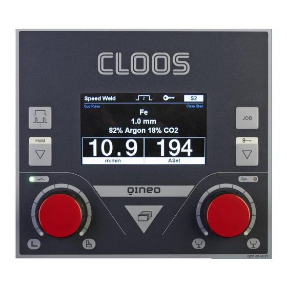
1. Structure and function 1.1 Operating panel Illustration 50. Master Plus Operating Panel Item Designation Function Selection key Op- 2 cycles, 4 cycles, Super-4 cycles, Spot weld- erating modes ing, External Job key Load, save, delete job Actual value display: m/min, mm, V, kW Hold key Display hold values Quick save selection (Jobs), setting the... -
Page 10: Display
Structure and function 1.2 Display Illustration 51. Master Plus Display Item Designation Function Process Display active processes Operating mode Display active operating mode Function lock Display locked functions active Job number Display active job/rapid memory LED: Green - Welding power source switched on Blue - Welding process runs Status display Red (blinking) - Error message... -
Page 11: Description Of Operating Modes
1.4 Description of operating modes The following operating modes can be selected: • 2 cycles • 4 cycles • Super 4 cycles • Spot welding/Interval • External 1.4.1 Definition 2-cycles Operating mode 2-cycles is provided for short manual welds. You can find additional information in the chapter 2.1 on page 1.4.2 Definition 4-cycles... -
Page 12: Description Of Processes
Structure and function 1.5 Description of processes The following welding processes will be described hereunder. 1.5.1 TIG Welding The process is provided with a Lift Start ignition. • Use the left rotary knob to select the welding current. The displays for wire diameter and shielding gas are hidden. 1.5.2 Electrode Welding All common stick electrodes can be welded in operating mode Electrode. - Page 13 Process Function This is a modified standard characteristic curve of "Control Weld". A very concentrated arc, ensuring a very deep penetration, is generated. Rapid Weld characteristic curves are available for the following material-gas-wire combinations. Rapid Weld (modified • Normal, Fe, 92% Ar, 8% CO2 wire 1,0 mm Control Weld) • Normal, Fe, 92% Ar, 8% CO2 wire 1,4 mm • Normal, Fe, 82% Ar, 18% CO2 wire 0,8 mm...
-
Page 14: Description Of Additional Functions
Structure and function 1.7 Description of additional functions The following additional functions are available in the selection menu for the basic and secondary parameters. Function Condition only if the selected characteristic curve offers this func- Duo Pulse tion only if the selected characteristic curve offers this func- Clean Start tion Diagnosis... -
Page 15: Clean Start
1.7.2 Clean Start Clean Start is a special ignition routine which ensures a reliable and low spatter arc ignition. The complete ignition routine runs in the millisecond range. 1.7.3 Diagnosis The machine model, performance class, data set number, the current version of the selected synergy characteristic curve and the software versions of the modules connected to the CAN bus are displayed in this menu. -
Page 16: Operation
Operation 2. Operation 2.1 Operating concept of the operating modes 2.1.1 Operating mode 2-cycles Torches Keystroke Welding time Main power Gas pre-flow + Start time: Upslope Downslope End crater Wire burnback + inching in 3 sec 1 sec 2 sec filling time: gas post-flow 3 sec... -
Page 17: Operating Mode 4-Cycles
2.1.2 Operating mode 4-cycles Torches Keystroke Welding time Main power Gas pre-flow + Start time: Upslope Downslope End crater Wire burnback + inching in 1 sec 3 sec 2 sec filling time: gas post-flow 3 sec 1st cycle --> Press and hold torch button •... -
Page 18: Operating Mode Super-4-Cycles
Operation 2.1.3 Operating mode Super-4-cycles Torches Keystroke Step 2 Step 3 Step 2 Step 1 Step 1 Torch Welding time Gas pre-flow + Downslope Upslope Burnback + Main power inching in 3 sec End crater filling 2 sec Gas post-flow Step modulation +2 Start time: time: Torch... -
Page 19: Operating Mode Spot Welding/Interval
2.1.4 Operating mode Spot welding/Interval Torches Keystroke Welding time Press and hold torch button • Solenoid valve for shielding gas opens • Weld voltage is applied on wire electrode • Wire feed starts • Arc ignites, weld current flows • Welding process stops automatically after expiration of the defined time. -
Page 20: Adjust Secondary Parameters
Operation 2.2.1 Adjust secondary parameters 1. Press the menu button. 2. Using the left rotary knob, select the menu for the secondary parameters for the characteristic curve and confirm it by pressing the knob. 3. Select the desired parameter by turning the left rotary knob and con- firm your selection by pressing the knob. -
Page 21: Additional Parameters Of Operating Mode "Super-4-Cycles
2.2.4 Additional parameters of operating mode "Super-4-cycles" In addition to the secondary parameters for the operating modes, "2-cycle" and "4-cycle", the following secondary parameters are available: • Start program (time) Correction value (Off, +/-99, torch) • Step Modulation Correction value (+/- 9,9 m/min) •... -
Page 22: Save And Load Job
Operation 2.3 Save and load job Individual, user-defined parameter settings (jobs) can be saved and loaded with a job number. The Master Plus operation has 994 storage spaces and 5 rapid memories for jobs. 2.3.1 Rapid memory access Five rapid storage spaces, S1 … S5, are available. Menu button Rotary knob Illustration 54. -
Page 23: Space Management
• Quick delete 1. Press the left rotary knob while the start screen is displayed. To open the start screen, press the menu button. 2. Turn the rotary knob to select a storage place. 3. Press the left rotary knob for approx. 4 seconds until the selected field turns yellow and "DEL"... - Page 24 Operation The following options are available in the space management: • Save job • Save job with name • Delete job • Job off (if job is loaded and active) • Save job 1. Using the rotary knob, select "Save job" in the space management and confirm your selection by pressing the knob.
- Page 25 Job key Illustration 56. Space management - Job off • Load job After you have saved your welding parameters in a job, you can use the job button to open a list of saved jobs. 1. Press the job button. •...
- Page 26 Operation • Delete job Only deactivated jobs can be deleted. To delete an active job, please first read the paragraph ("Deactivate active job"). 1. Hold the job button down until the space management appears. 2. Select the menu "Delete job" using the rotary knob. 3.
-
Page 27: Configuration Operating Panel
3. Configuration operating panel By holding down the "Hold" and "Job" buttons simultaneously, you can open the configuration menu. 1. Turn the rotary knob to select a menu item. 2. Confirm your selection by pressing the rotary knob. 3.1 Language •... -
Page 28: Basic Settings
Configuration operating panel 3.2 Basic settings In this menu, the basic settings for the use of the welding power source are made. 3.2.1 Basic screen Function Description Standard Basic setting of display In this setting, all other display elements are faded out ex- Dark cept for the wire feed and power indicators. -
Page 29: Control Voltage Mode
3.2.4 Control voltage mode Control voltages are analogue DC voltages from 0 … 10 Volt. They serve to control the parameters Power, ArcLength and ArcDynamic (dynamics) in the QINEO. Via an input-output-module (I/O module) the control voltages are passed on to the welding power source, for instance by a robot control. The control voltage operation is switched off if the number of control voltages is 0. -
Page 30: Mhw 405 Tq
Configuration operating panel 3.3.2 MHW 405 TQ This is used to set one of the following parameters for the additional torch buttons. Function Description The "Power", "Fine" (arc length), "Dynamic" and "Job" pa- rameters can be released and varied during the welding process using the torch button. -
Page 31: Job Continuation
3.3.4 Job continuation The job continuation is available for welding power sources with a soft- NOTICE! ware version of X.09 or higher. The job continuation can be applied in the 4-cycle and Super-4-cycle operating modes. If job continuation is active in Super 4-cycle, this has priority over the "Step modulation"... -
Page 32: For Software Version X.10 Or Higher
Configuration operating panel 3.4.2 For software version x.10 or higher The compensation is set via an automated measurement. Measurement is started at the operating panel via rotary knob. In the operating modes 2-cycles, 4-cycles, Super-4-cycles and spot welding it is also possible via torch button. - Page 33 • Ignition control The ignition control monitors the welding start for five seconds. If there is no welding signal within five seconds after start of welding, the error message "Err.24 Arc failure ignition phase" will appear. When the ignition control is off, wire feed will continue in case of a trou- WARNING! ble signal.
-
Page 34: Cooling Water Monitoring
Configuration operating panel 3.6 Cooling water monitoring In this menu, the settings for cooling water monitoring are made. Function Description Flow monitoring If there is a pending error message, this signal is Message transmitted for further processing (for instance by a PLC) to the CAN bus for the welding power source. -
Page 35: Sense Technology
3.8 QWD PushPull Which PushPull drive should be connected to which wire drive (QWD1 … QWD4) is configured here. • No drive • Cloos Arcette • Cloos Arcette 2 • Binzel PP+401D • TBI PPP 7G/7W • Dinse DIX MPZ 304 •... -
Page 36: Lock/Unlock Functions
Configuration operating panel 3.9 Lock/unlock functions The scope of the functions of the operating panel can be restricted on several levels. Lock functions Key button to lock and unlock the operating panel Locking symbol To activate the restrictions, press the "Key" button until the key symbol ap- pears at the top of the screen. -
Page 37: Access Management
3.9.1 Access management The access management differentiates between two operating levels: • Blocked • Released Use this menu to configure which functions are available for the user in blocked status and whether an access code must be entered to unlock the welding power source. -
Page 38: User Management And Pak
Configuration operating panel 3.9.2 User management and PAK Depending on the user level for login or as registered user, a coloured symbol appears at the top of the screen. Operating level when switching on: • "Automatic" • "Programmer" / Configurator" logged on user: •... - Page 39 Settings Function Description Operating level when switching on • "Automatic" The respective user level is activated after • "Programmer" switching on the machine. • "Configurator" Transfer of PAK data If a user whose user profile is not yet stored in the user management logs in with a PAK, the access is allowed or denied with this •...
- Page 40 Configuration operating panel Options Configure the user level "Automatic" in the submenu “Options”. Function Description Locking status The active access to the menus and welding settings is "complete" locked. The menus can only be opened and viewed. Rotary knob for fine adjustment is released. The menus "Release Fine"...
- Page 41 3.9.2.1 Create/edit/delete user profile If a user has a user profile, he can only call up the functions at the welding power source which are released for him. Log in to the welding power source with the access level "Configurator" to NOTICE! change user profiles.
- Page 42 Configuration operating panel Three operating levels are available: Abbrevia- Operating level Rights tion The user has unrestricted access rights to Configurator all menus and functions. The user must not make any configura- tion in the system. He may call and save Programmer all jobs.
-
Page 43: Pc Adaptation
If you want to activate additional options on your welding power source, call the CLOOS service hotline with the chip code and the serial number of the welding power source. You will then receive an activation code for a fee. - Page 44 Configuration operating panel MA_QN_MP...
Need help?
Do you have a question about the qineo PULSE MASTER-Plus and is the answer not in the manual?
Questions and answers