Table of Contents
Advertisement
Quick Links
Advertisement
Table of Contents

Related Manuals for Cloos Micro Pulse 300


Summary of Contents for Cloos Micro Pulse 300
- Page 1 Micro Pulse 300 01/15 Rev.0 - EN -...
- Page 2 Carl Cloos Schweisstechnik GmbH Industriestrasse 35708 Haiger Germany Telefon (0 27 73) 85-0 Telefax (0 27 73) 85-275 E-Mail: info@cloos.de Internet: http://www.cloos.de RW - FP - Rev.0 Ausgabedatum 3. 02 2015 Keep for fur ther use.
- Page 3 EU declaration of conformity No. CMM0516QNMIP3_01 Product description: MIG/MAG welding machine Model name: QINEO MICRO PULSE 300 Serial number: Refer to the nameplate on the back of the device Manufacturer: CARL CLOOS Schweisstechnik GmbH Address: Industriestrasse 22-36...
-
Page 4: Table Of Contents
Cod.006.0001.1721 Micro Pulse 300 22/04/2014 v2.0 ENGLISH CONTENTS INTRODUCTION ..................................... 5 INSTALLATION ...................................... 6 CONNECTIONS TO THE ELECTRICAL MAINS NETWORK ......................... 6 FRONT PANEL......................................6 REAR PANEL ......................................6 PREPARING FOR MMA WELDING ................................ 7 PREPARING FOR TIG WELDING ................................8 PREPARING FOR MIG/MAG WELDING ............................... - Page 5 LOADING A USER JOB ......................................... 36 6.8.3 DELETING A JOB .......................................... 37 TECHNICAL DATA ....................................38 SPARE PARTS ..................................... 40 MICRO PULSE 300 ....................................40 WIRE FEEDER MOTOR ..................................42 WIRE FEEDER ROLLS ..................................44 ELECTRICAL DIAGRAM ..................................45 4/50...
-
Page 6: Introduction
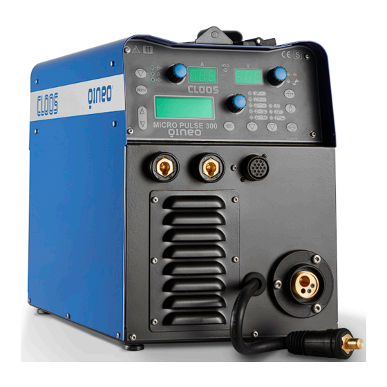
ENGLISH INTRODUCTION INTRODUCTION IMPORTANT! Micro Pulse 300 is a compact and rugged three-phase, synergic This handbook must be consigned to the user prior to inverter power source for MIG/MAG, MMA and TIG Lift welding. installation and commissioning of the unit. -
Page 7: Installation
Cod.006.0001.1721 Micro Pulse 300 22/04/2014 v2.0 ENGLISH INSTALLATION DANGER! REAR PANEL Lifting and positioning Read the warnings highlighted by the following symbols in the “General prescriptions for use”. CONNECTIONS TO THE ELECTRICAL MAINS NETWORK The characteristics of the mains power supply to which the equipment shall be connected are given in the section entitled “Technical data”... -
Page 8: Preparing For Mma Welding
Cod.006.0001.1721 Micro Pulse 300 22/04/2014 v2.0 ENGLISH PREPARING FOR MMA WELDING DANGER! Electric shock hazard! 1. Set the welding power source ON/OFF switch to “O” (unit de- Read the warnings highlighted by the following symbols in the energized). “General prescriptions for use”. -
Page 9: Preparing For Tig Welding
Cod.006.0001.1721 Micro Pulse 300 22/04/2014 v2.0 ENGLISH PREPARING FOR TIG WELDING 10. Connect the earth clamp to the workpiece being processed. 11. Set the welding power source ON/OFF switch to “I” (unit 1. Set the welding power source ON/OFF switch to “O” (unit de- powered). -
Page 10: Preparing For Mig/Mag Welding
Cod.006.0001.1721 Micro Pulse 300 22/04/2014 v2.0 ENGLISH PREPARING FOR MIG/MAG WELDING 2.6.1 WIRE SPOOL POSITIONING 1. Open the unit side door to gain access to the spool compartment. 2. Unscrew the cap of the spool holder. 2.6.2 POSITIONING THE WIRE IN THE WIRE FEEDER 1. -
Page 11: Connections To Sockets
Cod.006.0001.1721 Micro Pulse 300 22/04/2014 v2.0 ENGLISH 5. Feed the wire between the wire feeder rolls and insert it into the 2.6.3 CONNECTIONS TO SOCKETS MIG/MAG TORCH connector plug. 1. Set the welding power source ON/OFF switch to “O” (unit de- 6. - Page 12 Cod.006.0001.1721 Micro Pulse 300 22/04/2014 v2.0 ENGLISH 11/50...
-
Page 13: Commissioning
Cod.006.0001.1721 Micro Pulse 300 22/04/2014 v2.0 ENGLISH COMMISSIONING USER INTERFACE CODE SYMBOL DESCRIPTION MIG/MAG mode: When this LED illuminates the following parameter can be set: WELDING THICKNESS MIG/MAG mode: When this LED illuminates the following parameter can be set: WELDING CURRENT... -
Page 14: Unit Power-Up
Cod.006.0001.1721 Micro Pulse 300 22/04/2014 v2.0 ENGLISH CODE SYMBOL DESCRIPTION During illumination of the following LEDs: The display shows the value of the selected parameter. Welding: The display shows the effective amperes value during welding. HOLD function: The display shows the latest measured current value. -
Page 15: Reset (Load Factory Settings)
Cod.006.0001.1721 Micro Pulse 300 22/04/2014 v2.0 ENGLISH RESET (LOAD FACTORY SETTINGS) The reset procedure involves complete restoration of the default values, parameters and memory settings set in the factory. The reset procedure is useful in the following cases: - Too many changes made to the welding parameters so user finds it difficult to restore defaults. -
Page 16: Set-Up (Initial Set-Up Of The Welding Power Source)
Cod.006.0001.1721 Micro Pulse 300 22/04/2014 v2.0 ENGLISH SET-UP (INITIAL SET-UP OF THE WELDING POWER SOURCE) With locked status active it is not possible to access this function. § 3.5 LOCKING PROCEDURE Set the welding power source ON/OFF switch to “O” to switch the unit off. -
Page 17: Locking Procedure
Cod.006.0001.1721 Micro Pulse 300 22/04/2014 v2.0 ENGLISH CONTROL TYPE OFF= No remote controller enabled. RC03= The unit is enabled to receive commands from a remote control equipped with 1 potentiometer. RC04= The unit is enabled to receive commands from a remote control equipped with 2 potentiometer. -
Page 18: Gas Flow Adjustment
Cod.006.0001.1721 Micro Pulse 300 22/04/2014 v2.0 ENGLISH Disabling If a lock status is selected, you can only edit parameters permitted by the currently active lock status. If you cannot recall the password the only way to exit locked status is to perform the welding power source RESET procedure. -
Page 19: Alarms Management
Cod.006.0001.1721 Micro Pulse 300 22/04/2014 v2.0 ENGLISH ALARMS MANAGEMENT This LED illuminates if an incorrect operating condition occurs. An alarm message appears on the following display: D3 Tab. 3 - Alarm messages MESSAGE MEANING EVENT CHECKS - Make sure that the power required by the... -
Page 20: Welding Settings
Cod.006.0001.1721 Micro Pulse 300 22/04/2014 v2.0 ENGLISH WELDING SETTINGS TORCH TRIGGER MODES 4.1.1 2T MIG/MAG WELDING 1. Bring the torch up to the workpiece. 2. Press (1T) and keep the torch trigger pressed. The wire advances at the approach speed until making contact with the work. -
Page 21: B-L/3L Mig/Mag Welding
Cod.006.0001.1721 Micro Pulse 300 22/04/2014 v2.0 ENGLISH 4.1.6 4T B-L/3L MIG/MAG WELDING The welding process is the same as the 3L process except that during normal speed welding pressing and immediately releasing the torch trigger switches the unit to the second welding current. -
Page 22: Welding Parameters
Cod.006.0001.1721 Micro Pulse 300 22/04/2014 v2.0 ENGLISH WELDING PARAMETERS WELDING CURRENT - Lower gas consumption. - Oxidation of electrode tip (more difficult arc strike). Output current value during welding. ARC CORRECTION IN VOLTS HOT-START This parameter corrects the synergic voltage value relative to the This parameter aids electrode melting at the time of arc striking. - Page 23 Cod.006.0001.1721 Micro Pulse 300 22/04/2014 v2.0 ENGLISH PRE GAS SPOT TIME Time of gas delivery before the arc strike. When the torch trigger is pressed the welding arc persists for the time WARNING: an excessively long value will slow the welding procedure.
- Page 24 Cod.006.0001.1721 Micro Pulse 300 22/04/2014 v2.0 ENGLISH FREQ 2PULS Double pulsed frequency This parameter adjusts the frequency of alternation of the two wire feed rates set with the range 2puls parameter. The setting is dependent on the specific needs of the operator.
-
Page 25: Parameters Activation
Cod.006.0001.1721 Micro Pulse 300 22/04/2014 v2.0 ENGLISH PARAMETERS ACTIVATION The welding parameters are available in accordance with the selected welding mode and procedure. Certain parameters are available only after other parameters or functions of the unit have been enabled or set. -
Page 26: Characteristics Of The Menu Levels
Cod.006.0001.1721 Micro Pulse 300 22/04/2014 v2.0 ENGLISH CHARACTERISTICS OF THE MENU LEVELS 1ST LEVEL The menu shows the setting of the most important welding parameters (or synergic settings) relative to the selected welding process. SYN: This code indicates that parameters control is synergic. -
Page 27: 3Rd Level
Cod.006.0001.1721 Micro Pulse 300 22/04/2014 v2.0 ENGLISH 3RD LEVEL The menu contains the settings and values that are changed infrequently and are to be set up the first time the unit is powered up. The changed parameters remain saved until the next modification or reset of the unit. -
Page 28: Welding Settings
Cod.006.0001.1721 Micro Pulse 300 22/04/2014 v2.0 ENGLISH WELDING SETTINGS ELECTRODE WELDING (MMA) This button serves to select the following welding mode: 6.1.1 PARAMETERS SETTING Using the encoder, edit the value of the parameter. The value appears on the following display: D1 The value is saved automatically. -
Page 29: Mig/Mag Welding
Cod.006.0001.1721 Micro Pulse 300 22/04/2014 v2.0 ENGLISH MIG/MAG WELDING 6.3.1 WELDING CURVES SELECTION Use these buttons to select the following parameter: MAT Use these buttons to select the following parameter: Ø Use these buttons to select the following parameter: GAS... -
Page 30: Manual Mig/Mag Welding
Cod.006.0001.1721 Micro Pulse 300 22/04/2014 v2.0 ENGLISH MANUAL MIG/MAG WELDING Welding is of the Short/Spray type. Adjustment of the main welding parameters, wire feed rate and voltage is entirely at the discretion of the operator. The optimal work point must be identified for the required welding type. -
Page 31: Synergic Mig/Mag Welding
Cod.006.0001.1721 Micro Pulse 300 22/04/2014 v2.0 ENGLISH SYNERGIC MIG/MAG WELDING Set the welding data (material, wire diameter, gas type), shown on display D3 and just one welding parameter, chosen from among wire feed rate, Amperes, and workpiece Thickness, shown on display D1. -
Page 32: Synergic Mig/Mag Parameters Setting (2Nd Level)
Cod.006.0001.1721 Micro Pulse 300 22/04/2014 v2.0 ENGLISH 6.5.3 SYNERGIC MIG/MAG PARAMETERS SETTING (2ND LEVEL) Press the button to enter the 2nd level menu. Use these buttons to scroll through the list of parameters to edit. Using the encoder, edit the value of the selected parameter. -
Page 33: Pulsed Synergic Mig/Mag Welding
Cod.006.0001.1721 Micro Pulse 300 22/04/2014 v2.0 ENGLISH PULSED SYNERGIC MIG/MAG WELDING Set the welding data (material, wire diameter, gas type), shown on display D3 and just one welding parameter, chosen from among wire feed rate, Amperes, and workpiece Thickness, shown on display D1. -
Page 34: Pulsed Synergic Mig/Mag Parameters Setting (2Nd Level)
Cod.006.0001.1721 Micro Pulse 300 22/04/2014 v2.0 ENGLISH 6.6.3 PULSED SYNERGIC MIG/MAG PARAMETERS SETTING (2ND LEVEL) Press the button to enter the 2nd level menu. Use these buttons to scroll through the list of parameters to edit. Using the encoder, edit the value of the selected parameter. -
Page 35: Double Pulsed Synergic Mig/Mag Welding
Cod.006.0001.1721 Micro Pulse 300 22/04/2014 v2.0 ENGLISH DOUBLE PULSED SYNERGIC MIG/MAG WELDING Set the welding data (material, wire diameter, gas type), shown on display D3 and just one welding parameter, chosen from among wire feed rate, Amperes, and workpiece Thickness, shown on display D1. -
Page 36: Double Pulsed Synergic Mig/Mag Parameters Setting (2Nd Level)
Cod.006.0001.1721 Micro Pulse 300 22/04/2014 v2.0 ENGLISH 6.7.3 DOUBLE PULSED SYNERGIC MIG/MAG PARAMETERS SETTING (2ND LEVEL) Press the button to enter the 2nd level menu. Use these buttons to scroll through the list of parameters to edit. Using the encoder, edit the value of the selected parameter. -
Page 37: Jobs Management
Cod.006.0001.1721 Micro Pulse 300 22/04/2014 v2.0 ENGLISH JOBS MANAGEMENT Personalised welding settings, or JOBs, can be saved in memory locations and subsequently uploaded. Up to 99 jobs can be saved (j01-j99). The settings of the SETUP menu are not saved. -
Page 38: Deleting A Job
Cod.006.0001.1721 Micro Pulse 300 22/04/2014 v2.0 ENGLISH 6.8.3 DELETING A JOB Press the button. The job menu appears in the following displays: D3 Use these buttons to select the following parameter: OPT The selected parameter is shown by the following symbol: ... -
Page 39: Technical Data
Cod.006.0001.1721 Micro Pulse 300 22/04/2014 v2.0 ENGLISH TECHNICAL DATA Waste electrical and electronic equipment (WEEE) Electromagnetic compatibility (EMC) Directives applied Low voltage (LVD) Restriction of the use of certain hazardous substances (RoHS) Construction standards EN 60974-1; EN 60974-5; EN 60974-10 Class A... - Page 40 Cod.006.0001.1721 Micro Pulse 300 22/04/2014 v2.0 ENGLISH 40 % (40° C) 8.0 A 60 % (40° C) 8.2 A 100 % (40° C) 8.8 A 50 % (40° C) 6.2 A Maximum effective supply current 60 % (40° C) 6.4 A 100 % (40°...
-
Page 41: Spare Parts
Spare Parts Micro Pulse 300... - Page 42 order number description 0831 96 41 00 KNOB WITHOUT POINTER 0831 96 41 01 FRONT PANEL LABEL 0831 96 41 02 LOGIC BOARD PLATE 0831 96 41 03 LOGIC BOARD 0831 96 41 04 COMPLETE FRONT LOGIC PANEL 0831 93 00 07 POLARITY SELECTOR CABLE 0831 93 00 08 BLIND METAL FRONT PLATE...
-
Page 43: Wire Feeder Motor
order number description 0831 93 00 42 0831 93 00 43 FANS SUPPORT PLATE 0831 93 00 57 INTERNAL DEFLECTOR PLATE 0831 93 00 40 THERMAL CUT-OUT 75°C 0831 93 00 59 HEAT SINK 0831 93 00 41 THREE PHASE BRIDGE RECTIFIER 0831 93 00 46 DEFLECTOR PLATE 0831 93 00 39... - Page 44 WIRE FEEDER MOTOR order number description 0831 96 42 00 MOTOR COIL 0831 96 42 01 DISTANCE RING 0831 96 42 02 NUT M6 0831 96 42 03 NUT M5 0831 96 42 04 FEED PLATE 0831 96 42 05 SCREW M4x18 0831 96 42 06 SCREW M6x12...
-
Page 45: Wire Feeder Rolls
order number description 0831 96 42 07 SHAFT (1) 0831 96 42 08 MAIN GEAR DRIVE 0831 96 42 09 SHAFT (2) 0831 96 42 10 GEAR DRIVE 0046 03 45 12 FEED ROLL 0831 96 42 11 INTERNAL PROTECTION PLATE 0831 96 42 12 SCREW M5x10 0831 96 42 13... -
Page 46: Electrical Diagram
ELECTRICAL DIAGRAM THREE PHASE BRIDGE BLACK 050.000X.0057 BLACK BLACK MAINS SWITCH 050.000X.0044 4 5 6 J8 J6 BLACK BLACK HALL BLACK YELLOW_GREEN 050.000X.0091 FLAT 10V 9 10 12Vdc 12Vdc JP13-FLAT JP11 050.000X.0120 EARTH GIALLO/VERDE-YELLOW/GREEN 400VAC-1 MARRONE-BROWN 400VAC-2 400VAC-2 BLU-BLUE 18VAC-2 0VAC GND ISO 18VAC-2... - Page 47 THREE PHASE BRIDGE 050.000X.0044 J8 J6 HALL JP11 050.000X.0120 EARTH GIALLO/VERDE-YELLOW/GREEN 400VAC-1 MARRONE-BROWN 400VAC-2 BLU-BLUE GND ISO AL CU JP10 20 21...
- Page 48 THREE PHASE BRIDGE BLACK 050.000X.0057 BLACK BLACK MAINS SWITCH 4 5 6 J8 J6 BLACK BLACK BLACK YELLOW_GREEN 050.000X.0091 FLAT 10V 9 10 12Vdc 12Vdc JP13-FLAT JP11 050.000X.0120 400VAC-2 18VAC-2 0VAC 18VAC-2 18VAC-1 18VAC-1 24VAC-4 24VAC-4 24VAC-3 400VAC-1 48VAC-1 F1 6X32 2A 500V @ 48VAC-1 48VAC-2...
- Page 49 050.000X.0120 EARTH GIALLO/VERDE-YELLOW/GREEN 400VAC-1 MARRONE-BROWN 400VAC-2 BLU-BLUE GND ISO AL CU JP10 20 21 7 10 9 12 19 22 050.000X.0080 050.000X.0113 CN1 FLAT 34V 27 28 30 31 33 34 24VDC 21 22 24 25 27 28 30 31 33 34 CN3 FLAT 34V GND-ISO...
- Page 50 050.000X.0120 400VAC-2 0VAC 18VAC-2 18VAC-2 18VAC-1 18VAC-1 24VAC-4 24VAC-4 400VAC-1 24VAC-3 48VAC-1 F1 6X32 2A 500V @ 48VAC-1 48VAC-2 400VAC 48VAC-2 24VAC-3 20 21 B-RS485 19 22 A-RS485 DIG_OUT_2 DIG_OUT_1 DIG_IN_3 DIG_IN_2 DIG_IN_1 RX1-RS232 RX2-RS232 TX1-RS232 TX2-RS232 050.000X.0113 CN1 FLAT 34V 12 13 27 28 30 31...
- Page 51 www.qineo.de...
Need help?
Do you have a question about the Micro Pulse 300 and is the answer not in the manual?
Questions and answers