Table of Contents
Advertisement
Quick Links
Advertisement
Table of Contents

Related Manuals for Cloos GLW 302


Summary of Contents for Cloos GLW 302
- Page 1 Operating instructions and Spare parts GLW 302 - EN - Rev.1...
- Page 2 Carl Cloos Schweisstechnik GmbH Industriestrasse 35708 Haiger Germany Telephone: (0 27 73) 85-0 Telefax: (0 27 73) 85-275 E-Mail: info@cloos.de Internet: http://www.cloos.de RW - FP - Rev.1 release date: 03. 02. 2015 Keep for fur ther use!
- Page 3 CARL CLOOS Schweisstechnik GmbH Industriestrasse 35708 Haiger Tel.(+49) 2773/85-0 Fax.(+49) 2773/85-275 mail: info@cloos.de www.cloos.de Document: QIGLW302 Month/Year: 10/14 EC-Declaration of Conformity in accordance with EC Directives 2006/95/EG (low voltage) and 2004/108/EG (EMV) We herewith certify that the welding machine mentioned below has been developed, designed and manufactured in accordance with the EC Directives and brought on the market.
- Page 4 SPARE PARTS ..............28 PARTIAL RESET ..............9 ELECTRICAL DIAGRAM ............. 30 TOTAL RESET ..............10 16.1 GLW 302 ... FEHLER! TEXTMARKE NICHT DEFINIERT. SET-UP (INITIAL SET-UP OF THE WELDING POWER 16.2 TORCH CONNECTOR ............32 SOURCE) ................10 16.3 REMOTE CONTROLLER CONNECTOR ......
-
Page 5: Front Panel
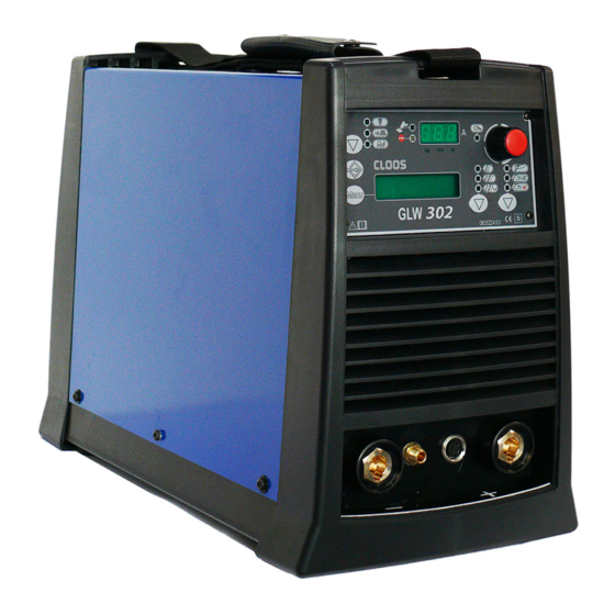
This symbol identifies a reference to a chapter of the manual. This symbol accompanies important information concerning the execution of the relevant operations. GLW 302 is an advanced technology single-phase welding power source for AC and DC TIG welding operations. AC TIG functions are ideal for aluminum, magnesium and related alloys welding. -
Page 6: Rear Panel
Cod.006.0001.1841 GLW 302 01/09/2014 v2.0 ENGLISH REAR PANEL PREPARING FOR MMA WELDING 1. Set the welding power source ON/OFF switch to “O” (unit de- energized). 2. Plug the power cable plug into a mains socket outlet. 1: Welding power source ON/OFF switch. - Page 7 Cod.006.0001.1841 01/09/2014 v2.0 GLW 302 ENGLISH PREPARING FOR TIG WELDING Installation with cooling unit 1. Set the welding power source ON/OFF switch to “O” (unit de- energized). 2. Remove the screws from the power source cabinet. 9. Connect the gas hose from the welding gas cylinder to the rear gas socket.
- Page 8 Cod.006.0001.1841 GLW 302 01/09/2014 v2.0 ENGLISH welding arc. 20. Use the flow control valve to adjust the flow of gas as required while the gas is flowing out. 21. Set the required welding parameter values on the user interface. When the remote control pedal is connected and the relative locking screw is tightened the welding current will vary in relation to the pressure exerted on the pedal.
-
Page 9: User Interface
Cod.006.0001.1841 01/09/2014 v2.0 GLW 302 ENGLISH USER INTERFACE CODE SYMBOL DESCRIPTION DC TIG mode: Illumination shows that the following function has been activated: Q-START AC TIG mode: Illumination shows that the following function has been activated: AC WAVE IN MIX AC-DC... -
Page 10: Unit Power-Up
Cod.006.0001.1841 GLW 302 01/09/2014 v2.0 ENGLISH Data setting: The display shows the various welding menus relative to the selected processes. The display shows the selected parameter. AC TIG mode: Press the button to select the parameter to be set. Possible choices:... -
Page 11: Set-Up (Initial Set-Up Of The Welding Power Source)
Cod.006.0001.1841 01/09/2014 v2.0 GLW 302 ENGLISH TOTAL RESET The reset procedure involves complete restoration of the default values, parameters and memory settings set in the factory. All memory locations will be reset and hence all your personal welding settings will be lost! Set the welding power source ON/OFF switch to “O”... - Page 12 Cod.006.0001.1841 GLW 302 01/09/2014 v2.0 ENGLISH Cooler activation ON= The cooler is always running when the power source is switched on. This mode is preferable for heavy duty and automatic welding procedures. OFF= The cooler is always disabled because an air-cooled torch is in use.
-
Page 13: Torch Loading
Cod.006.0001.1841 01/09/2014 v2.0 GLW 302 ENGLISH TORCH LOADING WARNING! Make sure the torch in use is correctly sized in relation to the welding current required and for the available and selected cooling type. This prevents the risk of burns to which the operator is potentially exposed, potential faults, and irreversible damage to the torch and the system. -
Page 14: Welding Parameters
Cod.006.0001.1841 GLW 302 01/09/2014 v2.0 ENGLISH WELDING PARAMETERS For a better understanding of the parameter functions described in the table, refer to the following diagram. (I1) TIG WELDING CURRENT (I2) BASE CURRENT (I3) FINAL CURRENT (I4) STARTING CURRENT (t1) UP SLOPE TIME... - Page 15 Cod.006.0001.1841 01/09/2014 v2.0 GLW 302 ENGLISH Peak time Spot TIG time Time for which the current pulse is at the maximum value. When the torch trigger is pressed the welding arc persists for the time set in the parameter. Consequences of a higher value: Press the torch trigger again to resume the welding process.
- Page 16 Cod.006.0001.1841 GLW 302 01/09/2014 v2.0 ENGLISH The following picture shows the positive wave interval ΔI that, if subtracted and added to the negative wave, forms the new form of broken line wave. Consequences of a higher value: Greater weld penetration.
- Page 17 Cod.006.0001.1841 01/09/2014 v2.0 GLW 302 ENGLISH 16/34...
- Page 18 Cod.006.0001.1841 GLW 302 01/09/2014 v2.0 ENGLISH 17/34...
-
Page 19: Welding Settings
Cod.006.0001.1841 01/09/2014 v2.0 GLW 302 ENGLISH WELDING SETTINGS 11.1 ELECTRODE WELDING (MMA) This button serves to select the following welding mode: 11.1.1 MMA PARAMETERS SETTING (1ST LEVEL) Press this button to scroll the list of settings to edit. The selected parameter and its value are shown on the following displays: D2 Using the encoder, edit the value of the selected setting. - Page 20 Cod.006.0001.1841 GLW 302 01/09/2014 v2.0 ENGLISH Tab. 5 - Special functions in MMA mode PARAMETER DEFAULT DYNAMIC ARC 11.2 DC TIG WELDING Use this button to select one of the following welding modes: DC TIG PULSED DC TIG SYNERGIC PULSED DC TIG...
- Page 21 Cod.006.0001.1841 01/09/2014 v2.0 GLW 302 ENGLISH PARAMETER DEFAULT SPOT TIG TIME 0.01 s 0.1 s 10.0 s HF ARC START REMOTE CONTROL MINIMUM PEDAL CURRENT 50 % 90 % *1: The activation is suitable for the following welding modes: MMA ...
-
Page 22: Ac Tig Welding
Cod.006.0001.1841 GLW 302 01/09/2014 v2.0 ENGLISH 11.3 AC TIG WELDING Use this button to select one of the following welding modes: AC TIG PULSED AC TIG Use this button to select one of the following torch trigger procedures: 2 STEP 2T SPOT 4 STEP 4 STEP BI-LEVEL 11.3.1 AC TIG PARAMETERS SETTING (1ST LEVEL) - Page 23 Cod.006.0001.1841 01/09/2014 v2.0 GLW 302 ENGLISH Tab. 10 - 2nd level menu parameters in AC TIG mode PARAMETER MIN DEFAULT MAX SPOT TIG TIME 0.01 s 0.1 s 10.0 s REMOTE CONTROL ON *1 MINIMUM PEDAL CURRENT 1 % 50 %...
-
Page 24: Jobs Management
Cod.006.0001.1841 GLW 302 01/09/2014 v2.0 ENGLISH JOBS MANAGEMENT Personalised welding settings, or JOBs, can be saved in memory locations and subsequently uploaded. Up to 50 jobs can be saved (j01-j50). The settings of the SETUP menu are not saved. 12.1 SAVING A JOB This function is available when welding mode is not active. -
Page 25: Torch Trigger Modes
Cod.006.0001.1841 01/09/2014 v2.0 GLW 302 ENGLISH NO STORED JOB The message appears only if there are saved JOBS, on the following displays: D2 Use the encoder to select the number of the job to be deleted. Exit without confirmation Press any button (except S2). -
Page 26: Bi-Level Lift Welding
Cod.006.0001.1841 GLW 302 01/09/2014 v2.0 ENGLISH 13.4 4T HF WELDING 1. Bring the torch up to the work until the electrode tip is approximately 2 or 3 mm away. 2. Press (1T) and release (2T) the torch trigger. The arc strikes without contact with the workpiece and the voltage discharges (HF) cease automatically. -
Page 27: Spot Hf Welding
Cod.006.0001.1841 01/09/2014 v2.0 GLW 302 ENGLISH 13.8 2T SPOT HF WELDING 1. Bring the torch up to the work until the electrode tip is approximately 2 or 3 mm away. 2. Press (1T) the torch trigger. The arc strikes without contact with the workpiece and the voltage discharges (HF) cease automatically. -
Page 28: Technical Data
Cod.006.0001.1841 GLW 302 01/09/2014 v2.0 ENGLISH TECHNICAL DATA Model GLW 302 EN 60974-1 Construction standards EN 60974-3 EN 60974-10 Class A Supply voltage 1 x 230V ~± 15 % / 50-60 Hz Mains protection 25 A Delayed Dimensions ( L x D x H ) - Page 29 Spare Parts...
- Page 30 order number description 0835 21 00 10 KNOB 0835 23 41 01 FRONT PANEL LABEL 0835 23 41 02 FRONT BOARD PLATE 0835 23 41 03 FRONT BOARD 0835 21 00 08 FRONT PLASTIC PANEL 0835 23 41 04 POWER TRANSFORMER 0835 23 41 05 OUTPUT INDUCTANCE 0835 21 00 05...
- Page 31 GAS CONNECTIONS COMPLETE KIT 0001 0835 21 00 43 SLEEVE HOSE ADAPTER FOR RUBBER HOSE 1/4 0835 23 41 28 Qineo GLW 302 Schlauchklemme 11-13 0835 21 00 45 HOSE CLAMP Ø=07-09 0835 21 00 46 SLEEVE HOSE ADAPTER FOR RUBBER HOSE M10 0835 21 00 47 AMPHT3360-001 M/5V.
- Page 32 Cooling Unit FC 10 BA_GLW-320_Rev. 03/16_DE...
- Page 33 Pos. / Artikelnummer / Bezeichnung description Item order number 0835 20 05 50 Schnellkupplung 1/8 Gas QUICK CLUTCH 1/8 GAS 0835 20 05 51 Reduziernippel I=1/8 A=1/8 F=1/8 - M=1/8 NIPPLE CONNECTOR 0835 20 05 52 Frontblech FRONT PLATE 0835 20 05 53 Reduziernippel I=1/4 A=1/4 F=1/4 - M=1/4 NIPPLE CONNECTOR SLEEVE HOSE ADAPTER FOR RUBBER HOSE...
- Page 34 Electrical Diagram GLW 302...
- Page 35 TORCH UP & DOWN TOR P.T. P.T. P.T. N.C. N.C. N.C. Torch Connector • Torch TORCH UP & DOWN TORCH P.T. P.T. P.T. P.T. N.C. N.C. DOWN N.C. N.C. • Up & Down-torch TORCH UP & DOWN TORCH P.T. P.T. P.T.
- Page 36 Remote Controller Connector • Torch with potentiometer Potentiometer 2 kΩ-10 kΩ • Remote controller Potentiometer 2 kΩ-10 kΩ • Foot pedal controller Potentiometer 2 kΩ-10 kΩ...
- Page 38 www.qineo.de...
Need help?
Do you have a question about the GLW 302 and is the answer not in the manual?
Questions and answers