Advertisement
Advertisement

Subscribe to Our Youtube Channel
Related Manuals for Tsurumi Pump 3PN


Summary of Contents for Tsurumi Pump 3PN
- Page 2 Tsurumi 3PN (50PN2.25S) 4PN (50PN2.4S) 8PN (50PN2.75S) Maintenance, Inspection & Overhaul...
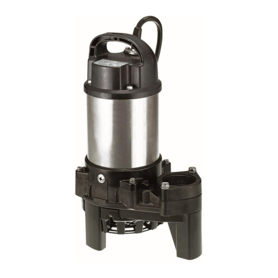
- Page 3 OVERHAUL MANUAL 3PN - 4PN – 8PN The following is a guideline for the inspection and overhaul of the PN Series water feature pumps. Use this guide, along with the parts list, exploded view diagram, and operation manual for your particular pump model to disassemble, inspect, and rebuild your pump to factory conditions.
-
Page 4: Table Of Contents
Sections Insulation Resistance Testing Page 6 Inspect Oil Chamber Page 11 Inspect Pump Casing Page 13 Inspect Mechanical Seal Page 16 Motor Inspection Page 25 Pump Re-Assembly Page 34... - Page 5 Tools Required...
-
Page 6: Insulation Resistance Testing
Insulation Resistance Testing Testing the resistance of a motor’s insulation system with a megohmeter (megger) ensures that the motor is not internally shorted, which can cause damage and/or injury. Check the pump’s maintenance manual for recommended testing intervals. - Page 7 Megger Test motor Set your Megger Tester to 2X the motor’s rated voltage (250V in this instance), and attach the testers red lead to one of the plug spades, and the testers black lead to the ground prong. Press the TEST button on the Megger and record readings after 20 seconds.
- Page 8 Cable Inspection Measure and inspect pump cable. Note total length of cable. Cables, as supplied, are 20’ in length (older units are 32’). If there are any cuts or other deformities in the cable, or the cable is less than 20’ in length, the cable should be replaced.
- Page 10 Bullet Cable Assembly Connectors Removal Using an 8mm socket or Phillips screwdriver, remove the two bolts securing the cable gland to the head cover. CAUTION: If water has worked it’s way into the motor area, this can be under pressure and water can spray out.
-
Page 11: Inspect Oil Chamber
Inspect Oil Chamber Tsurumi recommends to inspect the oil every 6 months of operation. If there is water in the oil chamber or the oil level is low, this is evidence of a worn mechanical seal, which should be replaced before irreparable damage occurs. - Page 12 Hex Bolt Drain and inspect oil To drain the oil, locate and remove the hex Oil Casing bolt located on the oil casing, on the side of the pump. Oil casing may be under pressure, so be sure to wear eye protection, and shield the oil from spraying everywhere.
-
Page 13: Inspect Pump Casing
Inspect Pump Casing for wear and/or debris If your pump is running but is not performing as new, there could be wear to the impeller or foreign debris stuck in the strainer or pump casing. - Page 14 Remove Pump Casing Using a 10mm socket, remove the hex screws securing the pump casing. With the pump casing removed, inspect the pump casing, impeller, and discharge flange for wear and damage. Any worn components should be replaced to regain original performance of the pump.
- Page 15 Remove Impeller With a #2 Phillips screwdriver bit on a cordless impact driver, remove the screw securing the impeller. It may be necessary to hold the impeller in place with pliers while unfastening the screw. Remove the impeller and set aside.
-
Page 16: Inspect Mechanical Seal
Inspect/Remove Mechanical Seal If oil or debris was found in the oil chamber, or oil level is low, it is necessary to change out the mechanical seal. - Page 17 Remove Oil Casing If there is evidence that mechanical seal is leaking (water or debris in the oil or motor Oil Casing has failed the Megger test), it will be necessary to remove the oil casing from the motor frame. Using a 5mm hex bit, remove the (4) bolts securing the oil casing.
- Page 18 Inspect oil casing, Mechanical Seal O-ring, oil lifter, and mechanical seal. It is recommended to use only new packings and O-rings upon re-assembly, so O-ring will NOT be re-used. Check for debris, or grit in the oil chamber, and make sure oil lifter is not cracked or otherwise damaged.
- Page 20 Remove oil lifter to Oil Lifter expose stationary seal. The oil lifter is press-fit into the oil casing. Carefully lift this off to allow removal of the stationary portion of the mechanical seal.
- Page 22 Carefully remove lower stationary seal from oil casing. Using a flat blade screwdriver, carefully pry the seal out of the casing. The seal will not be re-used, but we will want to inspect it, therefore we don’t want to crack or damage it in any way.
- Page 23 Remove lower (impeller side) rotary seal With two flat blade screwdrivers, CAREFULLY pry the lower portion of the rotary mechanical seal up and remove this face along with the spring. Take care not to damage the rotor shaft with the screwdrivers.
- Page 24 Remove upper (motor side) rotary seal With the upper seal and spring removed, remove the lower seal. Take care not to damage the rotor shaft with the screwdrivers. Pry ONLY from the top as shown, not from the bottom of the seal.
-
Page 25: Motor Inspection
Motor Inspection If your pump is tripping a circuit breaker or GFCI, this is evidence of an internal short in the motor or the cable. If your pump is making abnormal grinding noises or doesn’t spin, this is evidence of damaged bearings. Both would require disassembly and inspection of the motor components. - Page 26 Capacitor Motor Protector will be visible on the 8PN units. 3PN/4PN have the motor protectors placed in the motor windings. Using a marker or paint pen, mark the motor frame, motor head cover and packing for orientation upon reassembly.
- Page 27 (3PN, 4PN, and 8PN all use a 45µF capacitor) To be within tolerance, the capacitance should read within 5% of stated value. If it is...
- Page 28 Remove motor bracket Using a Phillips screwdriver bit, remove the (4) screws securing the Motor Bracket. Motor Bracket Place the motor on its side and tap the end of the shaft with a RUBBER OR PLASTIC hammer. A metal hammer can cause damage to the shaft end not allowing the impeller to be replaced.
- Page 29 Inspect rotor, stator and bearings With the motor bracket out of the way, pull up on the upper bearing Stator and the rotor assembly should slide out. If stator does not visibly have evidence of being burned, but is wet from oil or water, it will need to be cleaned with compressed air/mineral spirits and baked in an oven to properly dry.
- Page 30 Replace Bearings Spin bearings. If bearings appear to wobble or spin rough, they should be replaced. A bearing puller will be necessary to properly remove bearings. When re-installing NEW bearings, it is recommended to heat the bearings until the inner race reaches a temperature of 230°F and the inner diameter expands.
- Page 31 Tsurumi Motor Protectors MTP – 3PN/4PN CTP – 8PN...
- Page 32 Carefully remove upper stationary seals from bearing housing Carefully pry it out of the casing. The seal will not be re-used, but we will want to inspect it, therefore we don’t want to crack or damage it in any way.
- Page 33 Inspect all components for replacement With disassembly complete, inspect all the components for wear or damage, and make a list of components that will need to be replaced. A parts list with exploded view diagram is attached to the end of this guide. All packings and O-rings should be replaced along with the mechanical seal and oil.
-
Page 34: Pump Re-Assembly
Pump Re-Assembly Once all components have been verified to be in operable condition, we can now re-assemble the pump. New O-Rings and packing materials are available as a kit, and should always be used upon re-assembly... - Page 35 Lay out mechanical seal for proper placement It is very important that the mechanical seal components are oriented properly when installed. This is how they should appear on the shaft. Left to right = Top to bottom. Upper Stationary Upper (Motor Spring Lower (Impeller Lower Stationary...
- Page 36 Re-Assemble Stationary Seals Coat mechanical seal components with fresh oil. Carefully press upper stationary mechanical seal (ceramic) into motor frame, and press lower stationary seal (SiC) into the oil casing. Ensure seals are properly seated and sitting parallel to the casings. Press oil lifter into oil casing...
- Page 37 Re-Assemble Motor Set Bearing Housing on 2x4s, and place motor housing atop of bearing housing, lining up alignment marks from disassembly procedure.
- Page 38 Re-Assemble Motor Place rotor assembly back into motor frame/stator assembly. Place wave washer back onto top of upper bearing, and replace motor plate. Be sure to re-align the motor bracket and packing per the alignment marks drawn previously. Secure motor plate to bearing housing with the (4) M5x118mm bolts.
- Page 39 Secure motor assembly Re-install capacitor and attach leads from stator. For reference, the blue wire goes on the left (single lead), and black is on the right side – double lead. Replace head cover gasket and install head cover with the four securing bolts Be sure the white, red and green/yellow wires feed through the top of the head cover.
- Page 40 Reassemble Rotary Seals Coat rotor shaft with oil and carefully press upper rotary seal (flat edge) onto shaft until it touches the upper stationary seal. Place spring against rotary seal, and press lower rotary seal (chamfered edge) on the shaft. Recall that the upper (motor side) of the mechanical seal is identifiable by its rectangular indentation.
- Page 41 Reassemble Oil Casing Rotary seals will quickly compress on shaft, so run them back and forth on the shaft until oil casing is ready to be bolted to motor frame. Replace oil casing O-Ring and fasten oil casing to motor frame. Spin motor shaft to ensure there is no binding and shaft spins smoothly.
- Page 42 Re-assemble impeller Impeller vanes should face away from the motor. Secure impeller with truss screw & flat washer.
- Page 43 Vacuum test oil casing As an additional precaution, Tsurumi tests the seal chamber to be free from leaks before filling the chamber with oil by using a handheld vacuum pump and gauge. This step is completely optional. With an air tight fitting, we test that the mechanical seal is seated properly by pulling vacuum on the oil chamber.
- Page 44 Fill with new oil Using VG32 turbine oil or a 20W non-detergent motor oil. Fill oil casing with 8.1 oz. with a small funnel, or squirt bottle. Secure oil fill plug, using a new packing gasket.
- Page 45 Re-assemble wet end Set motor assembly upon pump casing. Ensure that tab in the oil casing is directly over the air purge valve so as to contain the ball. Fasten the motor to the casing with the 4 hex bolts.
- Page 46 Re-assemble Top End Connect bullet connectors of cable assembly to leads from motor housing. (White-White, Green-Green, Red-Black). Bullet connectors will ‘snap’ when they are fastened properly. Place leads back into head cover. Fasten gland to head cover using the (2) M5x20mm bolts. Ensure the metal gland is in its proper location.
- Page 47 Perform Run Test Connect pump cable to single phase 120V power. Make sure pump is pushing air and there is no abnormal noises coming from the unit. Pump should make a steady humming sound when running. If there are any questions, feel free to contact us at tech@tsurumipumpstore.com.
Need help?
Do you have a question about the 3PN and is the answer not in the manual?
Questions and answers