
Related Manuals for Velleman Velbus VMB1BL


Summary of Contents for Velleman Velbus VMB1BL
- Page 1 VMB1BL Blind Control Module for VELBUS system Velbus manual VMB1BL – edition 1 – rev.2.0...
-
Page 2: Table Of Contents
INDEX Features ............................3 Velbus data ............................ 3 Connection ............................ 4 Direct control through several push buttons ................4 Control through the VELBUS system ..................6 Combination of direct push button and VELBUS control............8 Connecting a 24V direct-current motor ................... 9 Use ............................... -
Page 3: Features
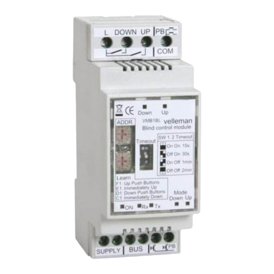
Features: ◊ Can be used to control an electric roll-down shutter, sunblind... ◊ Switching capacity at resistive load: 16A/230VAC max. ◊ Switching capacity at inductive load: 8A/230VAC max. ◊ Suppressed relay contacts. ◊ Manual control on the module. ◊ LED indications for: •... -
Page 4: Connection
CONNECTION For connection between the modules, use twisted pair cable (ex. EIB 2x2x0.8mm2, UTP 8x0.51mm - CAT5 or other). Use minimum 0.5mm² cable. For long wiring (>50m) or if a lot of modules ( > 10) are connected to one wire, use 1mm²... - Page 5 The up and down commands will be operated through a single push button as from firmware version 0804. DOWN AC POWER DOWN UP TIME ADDR VMB1BL ONE BUTTON CONTROL 12V SUPPLY Connection of the up and down commands, and the commands through a single push button is possible by using 2 diodes (1N4007).
-
Page 6: Control Through The Velbus System
Control through the VELBUS system: DOWN AC POWER DOWN UP TIME ADDR VMB1BL TWISTED PAIR (0.5mm ) 12V SUPPLY Combination of direct push button and VELBUS control: DOWN AC POWER DOWN UP TIME ADDR VMB1BL UP PUSH BUTTONS DOWN PUSH BUTTONS TWISTED PAIR (0.5mm ) 12V SUPPLY... - Page 7 The up and down commands will be operated through a single push button as from firmware version 0804. DOWN AC POWER DOWN UP TIME ADDR VMB1BL ONE BUTTON CONTROL TWISTED PAIR (0.5mm ) 12V SUPPLY Connection of the up and down commands, and the commands through a single push button is possible by using 2 diodes (1N4007).
-
Page 8: Connecting A 24V Direct-Current Motor
Connecting a 24V direct-current motor You can connect a 24V direct-current motor by using a transformer with 2 secondary windings and a bridge rectifier. MAINS 24DC Motor DOWN UP TIME ADDR VMB1BL UP PUSH BUTTONS DOWN PUSH BUTTONS TWISTED PAIR (0.5mm ) 12V SUPPLY Velbus manual VMB1BL –... -
Page 9: Use
USE: Remove the lid on the blind control module using a small screwdriver to modify the configuration. Relay contacts for blind motor control Direct push button control (COM connection) DOWN UP Up indication LED ADDR Down indication LED Switch-off setting Address setting TIME Manuel down operation... -
Page 10: Addressing
Addressing: Enter a unique address (from ‘00’ to ‘FE’ except for 'B1', ‘C1’, ‘D1’, ‘E1’, ‘F1’ and ‘FF’) for each module through the ‘ADDR’ rotating switches. These addresses can be used to learn the push buttons. In case of a modification of the addresses, the UP and DOWN outputs will be disabled and all LEDs of the corresponding push buttons will be turned out. -
Page 11: Learning Mode
Learning Mode: Only push buttons connected to the Velbus via a push button interface or a control panel are appropriate for the procedure below. Following push buttons can be learned: up, immediate up, down and immediate down. Each command can accept up to 14 different push buttons. - Page 12 Velbus manual VMB1BL – edition 1 – rev.2.0...
Need help?
Do you have a question about the Velbus VMB1BL and is the answer not in the manual?
Questions and answers