Advertisement
Quick Links
Advertisement

Related Manuals for Velleman Velbus VMB4PD


Summary of Contents for Velleman Velbus VMB4PD
- Page 1 VMB4PD Push Button and Timer Module for Velbus System VMB4PD...
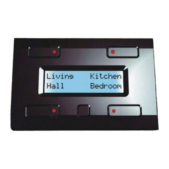
- Page 2 Push Button and Timer Module ® VMB4PD for Velbus System Introduction ® This unique panel will let you control all of the output modules on the Velbus system. There is no need to remember the function of each button, just read the label next to it! The module also features programmable timing functions to automate daily or weekly button press actions.
- Page 3 Power Supply: Required power voltage: 12 to 18VDC. Consumption: backlight off: 13mA LEDs off / 15mA LEDs on backlight lowly dimmed: 14mA LEDs off / 16mA LEDs on backlight highly dimmed: 18mA LEDs off / 19mA LEDs on backlight max. intensity: 26mA LEDs off / 27mA LEDs on Max.
- Page 4 Connection For connection between the modules, use twisted pair cable (ex. EIB 2x2x0.8mm , UTP 8x0.51mm - CAT5 or other). Use minimum 0.5mm² cable. For long wiring (>50m) or if a lot of modules ( > 10) are connected to one wire, use 1mm² cable. Connect the 12-18Vdc (mind the polarity) and connect the bus wires (mind the polarity).
- Page 5 Termination: ® Velbus Velbus® transmission LED reception LED Termination Velbus 9V back-up battery 12V power supply Velbus® power LED If the module is connected at the start or end of a cable on the VELBUS, place the ‘TERM’ jumper. Remove the jumper in all other cases. If different cable wiring topologies (tree, star, loop, ...) are used, place a jumper on the end module of the longest cable only, NOT on each end point.
- Page 6 The module consists of 4 push buttons with corresponding LED indication and one configuration push button. The label for each push button is displayed on the LCD. This module allows defining up to 8 commands. The module will display the first 4 commands by default: Indication LED command 1 Indication LED command 2 Command 1...
- Page 7 Configuration ® When using the module in the Velbus system for the first time, configure: • contrast • backlight • push button backlight • clock • address • labels • reaction time • mode • timer Call the configuration menu by holding the configuration pressed for 4 seconds. Configuration button The configuration menu will be displayed.
- Page 8 Remarks: • In configuration mode pressing the push buttons will no more be sent through the Velbus ® • All settings will be saved in the module (even with a power failure). • The first configuration menu shows menus “Prog” and “Timer on/off” when the timer is activated. •...
-
Page 9: Setting The Display Contrast
Setting the Display Contrast 1. Hold the configuration button pressed for 4 seconds to display the configuration menu. Configuration button 2. Press the upper right button to display the display menu. Display menu 3. Adjust the display contrast using the two upper buttons. Less contrast More contrast Next display menu... - Page 10 Setting the Display and Push Button Backlight The backlight intensity can be set according to your preferences (completely off, completely on or dimmed). The module allows you to automatically modify the intensity twice a day. The push button backlight intensity can also be set according to your preferences. This is useful when trying to locate the buttons in a completely dark room.
- Page 11 Backlight timer on/off Quit display menu 6. Press the configuration button to quit the display menu if the backlight timer has been deactivated. 7. Activate the backlight timer using the upper right button when you desire to automatically switch the backlight between two intensities. Backlight timer on/off 8.
-
Page 12: Setting The Clock
Setting the Clock You only need to set the clock from one module. All other modules connected in the system will adopt the set time. 1. Hold the configuration button pressed for 4 seconds to display the configuration menu. Configuration button 2. - Page 13 Setting the minutes 6. Confirm by pressing the upper left button. Confirm time Next clock menu Remarks: The seconds counter starts from 0 when setting the time. Wait for the beginning of a minute • Hold the configuration button pressed for 8 seconds to display the contrast mode. •...
- Page 14 Activating the Main Clock ® All modules (with clock function) connected onto the Velbus system must adopt the same time in order to work properly. This can be achieved by setting the main clock o none of the connected modules. This module will send ®...
- Page 15 Addressing ® Every module connected onto the Velbus system must have a unique address which can be set via the configuration menu. Make sure to synchronize the IR transmitter/receiver by setting the correct address. The final digit represents the address to be entered into the IR transmitter (see manual for the VMBIRTS transmitter).
- Page 16 Modifying the Labels It is possible to label all commands so as to explain their function. 1. Hold the configuration button pressed for 4 seconds to display the configuration menu. Configuration button 2. Press the configuration button again to display the configuration menu. Next configuration menu 3.
- Page 17 5. Move the cursor to the left or to the right using the two upper push buttons. Select the character using the two lower push buttons. Cursor to the left Cursor to the right Select character Select character Quit label editor 6.
- Page 18 Setting the Reaction Time All commands have a short reaction time (65ms) by default. This reaction time can be set at 1, 2 or 3 seconds. 1. Hold the configuration button pressed for 4 seconds to display the configuration menu. Configuration button 2.
- Page 19 5. Press the lower buttons to set a reaction time of 0, 1, 2 or 3 seconds for the displayed command. Press the configuration button to display the next configuration menu. Label command 3 Label command 4 Modify reaction time command 3 Modify reaction time command 4 Next reaction time menu 6.
-
Page 20: Setting The User Mode
Setting the User Mode The module can be used as a control panel or as a control panel with timer. The commands can be automated if the timer function has been activated. It is like you would activate a command at a particular time of the day. The timer function can be applied to all commands (Timer mode:8CH) or to the second set of commands only (Timer mode:4CH). -
Page 21: Programming The Timer
Programming the Timer Programming can only be done if the timer function was selected in the user mode. The commands can be automated via the timer function. It is like you would activate a command at a particular time of the day. Twenty program steps can be programmed; each step has a programmable time (day, hour and minutes) and command. - Page 22 4. Press the upper right button to display the next program step. Next program step Quit program menu 5. Press the lower right button to display the previous program step. Previous program step Quit program menu 6. Press the lower left button to modify the displayed program step. Next program step Modify program step Previous program step...
- Page 23 7. Press the upper right button to modify the day of the program step. Day setting Next program step setting You can choose from the following: Program step is executed every Monday Program step is executed every Tuesday Program step is executed every Wednesday Program step is executed every Thursday Program step is executed every Friday Program step is executed every Saturday...
- Page 24 10. Press the lower buttons to add or to remove the displayed command to or from the program step. Label command 1 Label command 2 Add or remove command 1 Add or remove command 2 Next program step setting Following symbols can be displayed: The command has not been accepted in the program step The command has been accepted in the program step.
- Page 25 13. Press the configuration button to display the next program step setting menu. Next program step setting 14. Press the lower buttons to add or to remove the displayed command to or from the program step. Label command 5 Label command 6 Add or remove command 5 Add or remove command 6 Next program step setting...
- Page 26 17. Press the configuration button to return to the general display Return to general display 18. Press the lower buttons to add or to remove the displayed command to or from the program step. Next program step Previous program step Quit program menu Let’s explain the example above: Command 1 will be executed every Monday morning at 08h30, commands 3, 5 and 8 will be...
- Page 27 Activating and Deactivating the Timer per Command The program will only be executed if the timer function for the command is activated. Deactivate the timer for the commands you do not want to be executed during a certain period (e.g. during vacation period).
- Page 28 4. Hold the configuration button pressed for 4 seconds to display the configuration menu. Configuration button 5. Press the lower right button to enter the timer activation menu. Timer activation menu The timer activation menu is possibly not available which means there is no command used in the program.
- Page 29 7. Press the configuration button to enter the next timer activation menu. Next timer activation menu The module exits the timer activation menu if commands 3 through 8 are not used in the program (go to section 14). Go to section 10 if commands 3 and 4 are not used in the program. Go to section 12 if commands 3 through 6 are not used in the program.
- Page 30 11. Press the configuration button to enter the next timer activation menu. Next timer activation menu The module exits the timer activation menu if commands 7 and 8 are not used in the program (go to section 14). 12. Press the lower buttons to activate or deactivate for the displayed commands. Label command 7 Label command 8 Activate/deactivate timer...
- Page 31 The timer function is deactivated by default and can be activated via the configuration menu (see section “Setting the User Mode”). The module consists of 4 push buttons with corresponding LED indication and one configuration push button. The label for each push button is displayed on the LCD. This module allows defining up to 8 commands.
- Page 32 Using the VMBIRTS IR Remote Stick All 8 commands can directly be activated using the IR remote stick. Point the IR remote stick towards the push button module and activate the desired channel on the stick (see the VMBIRTS manual). Activating commands 1 through 4 on the stick will make the module display the corresponding labels.
-
Page 33: Troubleshooting
Troubleshooting No display: • The display contrast is too low. Hold the configuration button pressed for 3 seconds to switch the module to the configuration menu which allows modifying contrast. Hold the upper right push button pressed for 8 seconds. The contrast will be set at its maximum. •... - Page 34 VMB4PD...
- Page 35 VMB4PD...
Need help?
Do you have a question about the Velbus VMB4PD and is the answer not in the manual?
Questions and answers