Table of Contents
Advertisement
Quick Links
Advertisement
Table of Contents

Related Manuals for socomec DIRIS A80


Summary of Contents for socomec DIRIS A80
- Page 1 _________ l � -' -------- - - Многофункциональный измерительный прибор Socomec Diris A80 - руководство по эксплуатации. Юниджет Постоянная ссылка на страницу: https://www.uni-jet.com/catalog/sistemyi-kommutaczii,- kontrolya-i-zashhityi/izmeritelnyie-priboryi/socomec-diris-a80.html...
- Page 2 DIRIS A80 Operating instructions...
-
Page 3: Table Of Contents
PRESENTATION ________________________________ 5 INSTALLATION _________________________________ 6 PROGRAMMING ______________________________ 10 OPERATION __________________________________ 57 RCM FUNCTION ______________________________ 63 CONNECTION TEST FUNCTION ________________ 66 ASSISTANCE _________________________________ 70 TECHNICAL CHARACTERISTICS ________________ 71 GLOSSARY OF ABBREVIATIONS ________________ 75 DIRIS A80 - Réf.: 540 275 B EN... -
Page 4: Danger And Warning
(V1, V2, V3 and VN) 700 V AC phase-to- phase or 400 V AC phase-to-neutral • a maximum current of 10 A on the current-input ter- minals (I1, I2 and I3) • u se only differential current transformers recom- mended by SOCOMEC Environment This product contains a lithium button battery. DIRIS A80 - Réf.: 540 275 B EN... -
Page 5: Preliminary Operations
For personnel and product safety please read the contents of these operating instructions carefully before connecting. Check the following points as soon as you receive the package: • the packing is in good condition, • t he product has not been damaged during transit, • t he product reference number conforms to your order, • t he packaging included a product itted with dis- connectable terminal strips, • a CD-ROM containing the operating instructions. DIRIS A80 - Réf.: 540 275 B EN... -
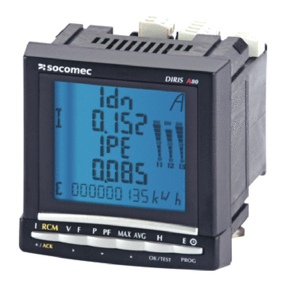
Page 6: Presentation
In addition to the functions of power management, detection of harmful events for electrical installation, the DIRIS A80 allows the monitoring of fault currents or RCM (Residual Current Monitoring) for TNS and TT systems. 2 references: • 4825 0213: Version with 2 outputs • 4825 0214: Version with 1 input and 1 output DIRIS A80 - Réf.: 540 275 B EN... -
Page 7: Installation
• I t is recommended to place the DIRIS A80 in a shielded enclosure in an environment with high greater than 1 G for frequencies lesser than 100 Hz. electromagnetic interference. CUT-OUT DIAGRAM, MOUNTING 3.54 in 90 mm 3.82 in 97 mm DIRIS A80 - Réf.: 540 275 B EN... - Page 8 Flat 2.5 M2 DIRIS A80 Aux.: 110 … 400 V AC / 120 … 350 V DC ‚ Fus.: IEC 0.5 A gG / BS88 2 A gG / 0.5 A class CC DIRIS A80 - Réf.: 540 275 B EN...
- Page 9 ‚ ‚ Fus.: IEC 0.5 A gG / BS88 2 A gG / 0.5 A class CC Fus.: IEC 0.5 A gG / BS88 2 A gG / 0.5 A class CC DIRIS A80 - Réf.: 540 275 B EN...
- Page 10 L3 ( T ) Aux.: 110 … 400 V AC / 120 … 350 V DC ‚ Fus.: IEC 0.5 A gG / BS88 2 A gG / 0.5 A class CC DIRIS A80 - Réf.: 540 275 B EN...
-
Page 11: Programming
DIRIS A80 PROGRAMMING ACCES TO PROGRAMMING MODE (COdE 100) The structure of the coniguration menu is the following: Software 4NBL 0500/5 version 3 sec. conirm DIRIS A80 - Réf.: 540 275 B EN... - Page 12 2 (2BL: two-phased) x 3 (3BL: three-phased balanced lines) x 4 (3NBL: three-phased unbalanced lines) x 5 (4BL: three-phased + neutral balanced lines) x 6 (4 NBL: three-phased + neutral unbalanced lines) conirm DIRIS A80 - Réf.: 540 275 B EN...
- Page 13 DIRIS A80 PROGRAMMING NOMINAL VOLTAGE OF THE NETWORK (phase/phase) (Example: 4NBL: U=390 V) This voltage corresponds to: • 1BL: phase-neutral voltage • 2 BL / 3BL / 3NBL / 4BL / 4NBL: phase-phase vol- tage T his value is used for deining the reference voltage (Ureg) for the detection of the voltage dips and inter- ruption, as well as voltage swells. DIRIS A80 - Réf.: 540 275 B EN...
- Page 14 DIRIS A80 PROGRAMMING CURRENT TRANSFORMERS (Example: CT = 1500 / 5 A). Max. 10000/5 or 10000/1 conirm DIRIS A80 - Réf.: 540 275 B EN...
- Page 15 DIRIS A80 PROGRAMMING NEUTRAL CURRENT TRANSFORMER (Example: CT = 1500 / 5 A). Max. 10000/5 or 10000/1 conirm DIRIS A80 - Réf.: 540 275 B EN...
- Page 16 DIRIS A80 PROGRAMMING VOLTAGE TRANSFORMER (Example: Ut = YES) conirm DIRIS A80 - Réf.: 540 275 B EN...
- Page 17 DIRIS A80 PROGRAMMING VOLTAGE TRANSFORMER PRIMARY (Example: PR = 20 000 V) Max. 500 000 V conirm DIRIS A80 - Réf.: 540 275 B EN...
- Page 18 DIRIS A80 PROGRAMMING VOLTAGE TRANSFORMER SECONDARY (Example: SE = 110 V) x 1 (110) x 2 (115) x 3 (120) x 4 (173) x 5 (190) x 6 (60) x 7 (100) conirm DIRIS A80 - Réf.: 540 275 B EN...
- Page 19 2 (30 min) x 3 (60 min) x 4 (2 sec.) x 5 (10 sec.) x 6 (5 min) x 7 (8 min) x 8 (10 min) x 9 (15 min) conirm DIRIS A80 - Réf.: 540 275 B EN...
- Page 20 1 (20 min) x 2 (30 min) x 3 (60 min) x 4 (10 sec.) x 5 (5 min) x 6 (8 min) x 7 (10 min) x 8 (15 min) conirm DIRIS A80 - Réf.: 540 275 B EN...
- Page 21 1 (20 min) x 2 (30 min) x 3 (60 min) x 4 (10 sec.) x 5 (5 min) x 6 (8 min) x 7 (10 min) x 8 (15 min) conirm DIRIS A80 - Réf.: 540 275 B EN...
- Page 22 1 (20 min) x 2 (30 min) x 3 (60 min) x 4 (10 sec.) x 5 (5 min) x 6 (8 min) x 7 (10 min) x 8 (15 min) conirm DIRIS A80 - Réf.: 540 275 B EN...
- Page 23 12 (ES) x 5 (MAX P-) x 13 (EA-) x 6 (MAX Q+) x 14 (ER-) x 7 (MAX Q-) x 15 (RCM) x 8 (MAX S) x 16 (MAX 4I) conirm DIRIS A80 - Réf.: 540 275 B EN...
- Page 24 DIRIS A80 PROGRAMMING OPERATING MODE OF BACKLIGHTING (Example: bACLIT = AUX) x 1 (AUX) x 2 (I) x 3 (U) x 4 (ON) conirm DIRIS A80 - Réf.: 540 275 B EN...
- Page 25 (Example: hour meter for current with start-up at 1000 A) x 1 (I) x 6 (E4) x 2 (U) x 7 (E3) x 3 (AUX) x 8 (E2) x 4 (E6) x 9 (E1) x 5 (E5) conirm conirm DIRIS A80 - Réf.: 540 275 B EN...
- Page 26 INTERNAL PULSE = synchronization with DIRIS inter- nal clock. EXTERNAL PULSE = synchronization as per the pulse received by the synchronization input of the memory module. x 1 (EXT) x 2 (INT) conirm DIRIS A80 - Réf.: 540 275 B EN...
- Page 27 INTEGRATION PERIOD OF THE MEMORY MODULE (Example: MEMO TIME = 10’) x 1 (20 min) x 2 (30 min) x 3 (5 min) x 4 (8 min) x 5 (10 min) x 6 (15 min) conirm DIRIS A80 - Réf.: 540 275 B EN...
- Page 28 I charge (A) Example: Alarm threshold curve with 6 points and 10 % hysteresis For a simpliied approach the user can only set a 2 points curve, for instance the point 1 corresponds to a minimum load and the point 2 to a maximum load in the installation. (mA) Seuil I∆n (mA) Seuil I Hystérésis I∆n (mA) Hystérésis I (mA) Seuil I∆n (mA) et hystérésis I charge (A) Example: Alarm threshold curve with 2 points and 10 % hysteresis DIRIS A80 - Réf.: 540 275 B EN...
- Page 29 The user has to give for each point 2 values: During the automatic learning process, the user has • Pt LD => Value of the current load to be able to change the load level of its installation • P t TH => Value of the threshold of the differential on a wide range in order to create the curve of the current nominal differential current according to the load cur- rent representative of the installation. CONFIGURATION MODE: Select “NO” to configure in MANUAL mode: see chapter “MANUAL MODE”, page 33. Select “YES” to conigure in AUTOMATIC mode: see chapter “AUTOMATIC LEARNING MODE”, page 29. DIRIS A80 - Réf.: 540 275 B EN...
- Page 30 By default the offset value is set to 0. Autoconf Autoconf I∆n and I I∆n and I Delay Offset Hysteresis I∆n and I I∆n and I I∆n and I Load Load Threshold Threshold DIRIS A80 - Réf.: 540 275 B EN...
- Page 31 The next point is automatically displayed and is acqui- red by following the same procedure. I∆n threshold When all the points have been acquired in the pre- vious “STEP” screen, press “▼” key up to reach the following screen: The offset is automatically applied on the alarm curve Choose the offset value by pressing “ ” then “▼” or when the user validates the auto coniguration. “▲” keys. The value is an offset on IΔn measured value. DIRIS A80 - Réf.: 540 275 B EN...
- Page 32 The offset is automatically applied on the tripping curve when the user validates the auto coniguration. “▲” keys. The value is an offset on I measured value. IΔn hysteresis Press “▼” key up to reach the following screen: Choose the hysteresis value by pressing “ ” then The hysteresis is automatically applied on the tripping curve when the user validates the auto coniguration. “▼” or “▲” keys. The value is given in percentage of IΔn threshold. DIRIS A80 - Réf.: 540 275 B EN...
- Page 33 The hysteresis is automatically applied on the tripping curve when the user validates the auto coniguration. “▼” or “▲” keys. The value is given in percentage of I threshold. Auto coniguration end Press “▼” key up to reach the following screen: The user selects “YES” to validate the auto learning, The acquired points are displayed on the following or “NO” to quit this function. screens. DIRIS A80 - Réf.: 540 275 B EN...
- Page 34 Pt2 : TH Pt2/I∆n Pt1/I∆n Pt1 : TH I charge (A) Pt1 : LD Pt2 : LD 12 screens allow the user to change the current load Press “▼” key up to reach the following screen: (LD) and threshold (TH) values to set the IΔn alarm curve. Up to 6 points. DIRIS A80 - Réf.: 540 275 B EN...
- Page 35 Select I∆n threshold by pressing “ ” key and select the previous procedure for load current and threshold “TH” with “▼” or “▲” keys. settings of each point. Choose the value by pressing “ ” then “▼” or “▲” keys for each digit and range. Note: If less than 6 points are used. The remaining points have to be set to 0. Once the correct value is obtained validate by pres- sing ”OK” key. DIRIS A80 - Réf.: 540 275 B EN...
- Page 36 DIRIS A80 PROGRAMMING IΔn hysteresis The hysteresis is set once for all the points of the curve. Set the hysteresis screen by pressing “▼”key: Choose the value by pressing “ ” then “▼” or “▲” keys. The value is given in percentage of IΔn. DIRIS A80 - Réf.: 540 275 B EN...
- Page 37 IΔn – point 4 – LD IΔn – point 4 – TH IΔn – point 5 – LD IΔn – point 5 – TH IΔn – point 6 – LD IΔn – point 6 – TH IΔn - hysteresis 5 % IΔn - delay 0,10 s ALARM SETTINGS The procedure to set I alarm is similar to the pre- vious one for IΔn settings. DIRIS A80 - Réf.: 540 275 B EN...
- Page 38 Press “▼” key up to reach the following screen: Choose the delay value by pressing “ ” then “▼” or “▲” keys for each digit and range. Different types of inputs can be selected. TYPE “---” : No assignment “ACK”: A ckowledgement of alarm “SEN: Tests of sensors “RMS”: S tart RMS curve “AVG”: S tart AVG curve DIRIS A80 - Réf.: 540 275 B EN...
- Page 39 DIRIS A80 PROGRAMMING Input state Press “▼” key up to reach the following screen: Choose the value by pressing “ ” then “▼” or “▲” keys. The state of the input relay can be Normally Close (NC) or Normally Open (NO). DIRIS A80 - Réf.: 540 275 B EN...
- Page 40 “SE”: Sensor 1 or 2 defect Output relay states The state of the relay can be Normally Close (NC) or Normally Open (NO). When the DIRIS A80 is powered off the relays are open. Press “▼” key up to reach the following screen: DIRIS A80 - Réf.: 540 275 B EN...
- Page 41 “FULL”: a cknowledgment from ACK button or supervi- sion or input (if input available) “EXT”: acknowledgment from supervision or input (if input available) 3. Activation of I current transformer Press “▼” key up to reach the following screen: Change by pressing “ ” then “▼” or “▲” keys. TYPE “YES” : To activate I current transformer “NO” : T o not activate I current transformer DIRIS A80 - Réf.: 540 275 B EN...
- Page 42 DIRIS A80 which is 29 V AC neutral phase and 50 V AC phase/phase must be taken into account. > Over-currents The detection threshold is conigured in % of the CT rating. Detection is made as in the case of voltage swell. Enregistrement de 1,2s Ureg = 400V Hystérésis = 380V Seuil = 360V EVENEMENT Example: Voltage dips with a 90 % voltage threshold and 5 % hysteresis. DIRIS A80 - Réf.: 540 275 B EN...
- Page 43 DIRIS A80 PROGRAMMING THRESHOLD OF VOLTAGE DIPS (SAG) (Example: dAtA SAG = 90 %) % of the nominal voltage. Example: 90 % for 400 V, when SAG is < 360 V. conirm DIRIS A80 - Réf.: 540 275 B EN...
- Page 44 DIRIS A80 PROGRAMMING HYSTERESIS OF VOLTAGE DIPS (Example: dAtA HySt SAG = 5 %) conirm DIRIS A80 - Réf.: 540 275 B EN...
- Page 45 DIRIS A80 PROGRAMMING (Example: dAtA INTER = 13 %) THRESHOLD OF VOLTAGE INTERRUPTION (INTER) conirm DIRIS A80 - Réf.: 540 275 B EN...
- Page 46 DIRIS A80 PROGRAMMING HYSTERESIS OF VOLTAGE INTERRUPTION (INTER) (EXAMPLE: DATA HYST INTER = 5 %) conirm DIRIS A80 - Réf.: 540 275 B EN...
- Page 47 DIRIS A80 PROGRAMMING THRESHOLD OF VOLTAGE SWELL (SWELL) (Example: dAtA SWELL = 115 %) conirm DIRIS A80 - Réf.: 540 275 B EN...
- Page 48 DIRIS A80 PROGRAMMING HYSTERESIS OF VOLTAGE SWELL (SWELL) (Example: dAtA HySt SWELL = 5 %) conirm DIRIS A80 - Réf.: 540 275 B EN...
- Page 49 DIRIS A80 PROGRAMMING THRESHOLD OF OVER-CURRENTS (OVER) (Example: dAtA OVER I = 115 %) conirm DIRIS A80 - Réf.: 540 275 B EN...
- Page 50 DIRIS A80 PROGRAMMING HYSTERESIS OF OVER-CURRENTS (Example: dAtA HySt I = 5 %) conirm DIRIS A80 - Réf.: 540 275 B EN...
- Page 51 DIRIS A80 PROGRAMMING CONFIGURABLE TRIGGER FOR RMS 1/2 PERIOD CURVES (Example: MOdE PRE-POST = 30 % - 70 %) DIRIS A80 - Réf.: 540 275 B EN...
- Page 52 DIRIS A80 PROGRAMMING CONFIGURABLE TRIGGER FOR RMS 1/2 PERIOD CURVES (Example: MOdE PRE-POST = 30 % - 70 %) conirm DIRIS A80 - Réf.: 540 275 B EN...
- Page 53 DIRIS A80 PROGRAMMING MODIFICATION OF THE DATE / TIME FUNCTION: YES / NO (By default no timestamping) x 1 (YES) x 2 (NO) conirm DIRIS A80 - Réf.: 540 275 B EN...
- Page 54 DIRIS A80 PROGRAMMING DATE SETTINGS (Example: dAtE = DD-MM-YY) conirm DIRIS A80 - Réf.: 540 275 B EN...
- Page 55 DIRIS A80 PROGRAMMING HOUR SETTINGS (Example: tIME 14h02’30”) conirm DIRIS A80 - Réf.: 540 275 B EN...
- Page 56 DIRIS A80 PROGRAMMING MODIFICATION OF THE ACCESS CODE IN THE CONFIGURATION MENU (Example: COdE = 200) conirm DIRIS A80 - Réf.: 540 275 B EN...
- Page 57 DIRIS A80 PROGRAMMING SERIAL NUMBER (Example: SErl = 110433120100) SOFTWARE VERSION (Example: version 100) EXIT PROGRAMMING 3 sec. DIRIS A80 - Réf.: 540 275 B EN...
-
Page 58: Operation
DIRIS A80 OPERATION DIRIS A80 - Réf.: 540 275 B EN... - Page 59 DIRIS A80 OPERATION DIRIS A80 - Réf.: 540 275 B EN...
- Page 60 DIRIS A80 OPERATION DIRIS A80 - Réf.: 540 275 B EN...
- Page 61 DIRIS A80 OPERATION x 13 x 10 x 14 x 11 x 15 x 12 x 16 DIRIS A80 - Réf.: 540 275 B EN...
- Page 62 DIRIS A80 OPERATION x 18 DIRIS A80 - Réf.: 540 275 B EN...
- Page 63 DIRIS A80 OPERATION DIRIS A80 - Réf.: 540 275 B EN...
-
Page 64: Rcm Function
DIRIS A80 RCM FUNCTION IΔn AND I CURRENT TRANSFORMER DETECTION A special screen will be displayed to inform the user if a current transformer is not connected or in default. This screen can be removed by pressing any key. Example: Current transformer issue on IΔn input DIRIS A80 - Réf.: 540 275 B EN... - Page 65 For alarm acknowledgment, the user presses the see Alarm acknowledgment settings for more details), “ACK” key (3 sec.). this screen stays on while the alarm is active or the When the alarm is acknowledged, the product returns user has not validated it. to its default screen. Return to User Alarm on Alarm is Print screen acknowledg- default inished I∆n detected “alarm I∆n” ment screen DIRIS A80 - Réf.: 540 275 B EN...
- Page 66 If the alarm auto acknowledgment is off (type “AUTO” to its default screen. see Alarm acknowledgment settings for more details), this screen stays on while the alarm is active or the user has not validated it. Threshold Hysteresis Maximum value Current value Return to User Alarm on Alarm is Print screen acknowledg- default inished detected “alarm I ” ment screen DIRIS A80 - Réf.: 540 275 B EN...
-
Page 67: Connection Test Function
Err 6 = V 3 and V1 voltages inverted Err 7 = RCM fault For the Err 1, Err 2 and Err 3, the modiication can be performed automatically by the DIRIS or manually by correcting the current connections. For the Err 4, Err 5 and Err 6 the modiication must be performed manually by correcting the voltage 3 sec. connections. DIRIS A80 - Réf.: 540 275 B EN... - Page 68 DIRIS A80 TEST FUNCTIONS Example: tESt Err 0 3 sec. 3 sec. DIRIS A80 - Réf.: 540 275 B EN...
- Page 69 DIRIS A80 TEST FUNCTIONS Example: tESt Err 2 3 sec. 3 sec. DIRIS A80 - Réf.: 540 275 B EN...
- Page 70 TEST FUNCTIONS > Second test operation This menu is displayed if the product has already been tested. You can run a full test again as explai- ned below. This action will delete the previous software correc- tions. 3 sec. DIRIS A80 - Réf.: 540 275 B EN...
-
Page 71: Assistance
• C urrent = 0 or incorrect Verify the connections Verify the coniguration of CT’s in set up • P owers, power-factor and energies false Use the test connection function (p. 48) • Phases missing on display Check the Network coniguration (p. 9) DIRIS A80 - Réf.: 540 275 B EN... -
Page 72: Technical Characteristics
45.0 to 65.0 Hz Update period: Power supply IEC 110 to 400 V AC 50/60 Hz ± 10 % 120 to 350 V DC ± 20 % < 10 VA Consumption: Synchro input Forward voltage max. 30 V DC Forward voltage min. 10 V DC Reverse voltage max. 30 V DC Galvanic insulation 3 kV Minimum pulse width Max number of operating cycles DIRIS A80 - Réf.: 540 275 B EN... - Page 73 30 to 350 V AC ph/n PFv 0.5 ind to 0.8 cap Pst, Plt Unavailable function on A80 5 to 100 % Un Udip 100 to 120 % Un Uswl Unavailable function on A80 0 to 5 % Un Uint Unavailable function on A80 Unba Fn = 50 Hz - rank 1 to 63 Fn = 60 Hz - rank 1 to 63 THDu Unavailable function on A80 THD-Ru Fn = 50 Hz - rank 1 to 63 Fn = 60 Hz - rank 1 to 63 THDi Unavailable function on A80 THD_Ri Unavailable function on A80 DIRIS A80 - Réf.: 540 275 B EN...
- Page 74 1 or 2 (according to reference) Type of contact: Relay 230 VAC - 1 A CONNECTION I∆n / I differential current transformer: Disconnectable terminals 0.14 to 1.5 mm Input / Output: Disconnectable terminals 0.2 to 2.5 mm DIRIS A80 - Réf.: 540 275 B EN...
- Page 75 IEC 60068-2-6 - 2 G Insulation ELECTRIC SECURITY: IEC 61010-1 INSTALLATION CATEGORY: III (300 VAC PH/N) DEGREE OF POLLUTION: REFERENCES DIRIS A80 WITH 2 OUTPUTS 4825 0213 DIRIS A80 WITH 1 INPUT AND 1 OUTPUT 4825 0214 DIRIS A80 - Réf.: 540 275 B EN...
-
Page 76: Glossary Of Abbreviations
THD In Neutral current distortion rate THD U Phase-to-phase voltage distortion rate THD V Phase-to-neutral voltage distortion rate tIME Hours / minutes / seconds tIME Synchronisation period tIME 4I Integration times for mean and maximum current values tIME F Integration times for mean and maximum frequency values tIME P/Q/S Integration times for mean and maximum power values tIME U Integration times for mean and maximum voltage values Synchronizing pulses Unbalance Voltage transformer DIRIS A80 - Réf.: 540 275 B EN... - Page 77 DIRIS A80 GLOSSARY OF ABBREVIATIONS U nOM Nominal voltage Ut PR Voltage transformer primary Ut SE Voltage transformer secondary Hour run meter DIRIS A80 - Réf.: 540 275 B EN...
- Page 78 Pt3: point 3 Pt3: point 3 Pt4: point 4 Pt4: point 4 Pt5: point 5 Pt5: point 5 Pt6: point 6 Pt6: point 6 Hyst: Hysteresis Hyst: Hysteresis Dly : Delay Dly : Delay DIRIS A80 - Réf.: 540 275 B EN...
- Page 79 DIRIS A80 NOTES DIRIS A80 - Réf.: 540 275 B EN...
- Page 80 DIRIS A80 NOTES DIRIS A80 - Réf.: 540 275 B EN...
- Page 81 YOUR DISTRIBUTOR DEPARTMEnT SOCOMEC GROUP SOCOMEC S.A. SOCOMEC capital 10 951 300 € 1, rue de Westhouse - B.P. 60010 R.C.S. Strasbourg B 548 500 149 F - 67235 Benfeld Cedex - FRANCE B.P. 60010 - 1, rue de Westhouse Tel.
Need help?
Do you have a question about the DIRIS A80 and is the answer not in the manual?
Questions and answers