Table of Contents
Advertisement
Quick Links
Exos AP 4U100 Hardware Installation
and Maintenance Guide
Abstract
This document describes initial hardware setup for Seagate Exos AP 4U100 enclosures. It also describes removal and
installation of customer-replaceable units for these enclosures. The document is intended for use by storage system
administrators familiar with servers and computer networks, network administration, storage system administration
and configurations, storage area network management, and relevant protocols.
Firmware Version: Latest available firmware build
P/N 83-00007252-11-01
Revision A
April 2021
Advertisement
Table of Contents
Troubleshooting

Related Manuals for Seagate Exos AP 4U100


Summary of Contents for Seagate Exos AP 4U100
- Page 1 Maintenance Guide Abstract This document describes initial hardware setup for Seagate Exos AP 4U100 enclosures. It also describes removal and installation of customer-replaceable units for these enclosures. The document is intended for use by storage system administrators familiar with servers and computer networks, network administration, storage system administration and configurations, storage area network management, and relevant protocols.
- Page 2 In addition, some of the listed capacity is used for formatting and other functions, and thus will not be available for data storage. Actual data rates may vary depending on operating environment and other factors. The export or re-export of Seagate hardware or software is regulated by the U.S. Department of Commerce, Bureau of Industry and Security (for more information, visit www.bis.doc.gov), and may be controlled for export, import and use in other countries.
-
Page 3: Table Of Contents
Contents Acronyms ............... 11 About this guide . - Page 4 Preparing for installation ..................46 Preparing the site .
- Page 5 Replacing a system fan module ................93 Removing a system fan module .
- Page 6 ASL Functionality ..................127 Intel Reference Code POST Code .
- Page 7 Figures 1 4U100 enclosure system - dimetric front orientation ............19 2 4U100 enclosure system –...
- Page 8 49 Release both safety lock latches ................66 50 Attachment of the CMA C bracket assembly to the CMA A bracket on the chassis .
- Page 9 100 BIOS phase indication mediums ................122 Figures...
- Page 10 9 Exos AP 4U100 product components ........
-
Page 11: Acronyms
Acronyms Table 1 Acronyms Acronym Description 10GbE 10 Gigabit per second Ethernet Alternating Current ANSI American National Standards Institute ASIC Application-Specific Integrated Circuit Advanced Technology Attachment Advanced Technology Extended BIOS Basic Input/Output System Baseboard Management Controller Command Line Interface Cable Management Arm Converged Network Adapter CPLD Complex Programmable Logic Device... - Page 12 Table 1 (continued)Acronyms Acronym Description High Availability Host Bus Adapter Hard Disk Drive HTTP Hypertext Transmission Protocol Inter-Integrated Circuit IANA Internet Assigned Numbers Authority Inter-Controller Link Input/Output Input/Output Hub IPMI over LAN IOPs I/Os Per second Internet Protocol iSCSI Internet Small Computer System Interface JBOD Just a Bunch of Disks Keyboard Controller Style...
- Page 13 Table 1 (continued)Acronyms Acronym Description Solid State Drive Secure Shell Serial SCSI Protocol Video Graphics Array Vital Product Data...
-
Page 14: About This Guide
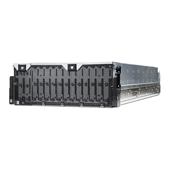
This guide provides information about initial hardware installation and setup, as well as removal and installation of customer replaceable units (CRUs) for the Seagate Exos AP 4U100 enclosure. The Exos AP 4U100 is a high capacity server enclosure designed for use in Cloud and Enterprise environments. The Exos AP 4U100 measures 4 EAI units of rack height (7") and fits a 1.2 m rack. - Page 15 CAUTION: Indicates that failure to follow directions could result in damage to equipment or data. IMPORTANT: Provides clarifying information or specific instructions. NOTE: Provides additional information. TIP: Provides helpful hints and shortcuts. Document conventions and symbols...
-
Page 16: Safety Guidelines
A safe lifting height by hand or without a mechanical server lift is 20U (~35”). • The Exos AP 4U100 ships with CRUs installed, except drives. The drives should be only be installed after verifying the enclosure is securely mounted into the rack. -
Page 17: Restricted Access
• Exos AP 4U100 enclosures are intended to operate with two PSUs and four fans accessed from the rear panel. Two controller channel fan modules accessed from the top of the enclosure provide additional cooling. -
Page 18: Rack System Safety Precautions
Rack system safety precautions The following safety requirements must be considered before mounting the enclosure is mounted in a rack. • Before installing Exos AP 4U100 into the rack, see the CAUTION on page 16 and the WARNING on page 63 •... -
Page 19: System Overview
System overview Enclosure configuration The Exos AP 4U100 storage system supports a 4U (rack space) chassis – refer Figure 1 Figure 2. It holds up to 96 LFF HDDs in main bay, and 4 SFF (2.5”) HDD or SSD (3.5”) modules in controller channel bay in a vertical orientation (hence, the term: 4U100). -
Page 20: Enclosure Variants
Enclosure variants The 4U100 enclosure is an application platform which can act as a server. There are two types of 4U100 enclosure variants based upon the type of CMA assembly. Throughout the document, the word “CMA” refers to the Cable Management Arm along with its associated brackets. -
Page 21: Enclosure Main Components
Enclosure main components The design concept is based on an enclosure subsystem together with a set of plug-in modules. A typical enclosure system—as supplied—includes the following: • An enclosure chassis equipped with several PCBs, including a midplane, sideplane, and baseplane PCBs, and a cluster of integral enclosure status LED indicators located at the lower left area of the enclosure front panel, near the left ear. -
Page 22: Enclosure Front Panel
Enclosure front panel Description Description Pull-handle (left) Pull-handle (right) Controller channel bay lid latch Enclosure system LEDs Main bay lid latch Figure 3 4U100 enclosure system – front panel view The enclosure front panel displays seven (7) main enclosure system LEDs, which are located in the lower left corner. See Figure 15 (page 32). -
Page 23: Enclosure Rear Panel
Enclosure rear panel This enclosure rear panel view intentionally omits the lift handles that attach to the enclosure sides. For clarity, it also omits the rail kit components that are used when installing the enclosure into the rack. Description Description Right ear assembly (as viewed from back) MiniSAS HD ports (quantity 4) System fan module (quantity 4) -
Page 24: 4U100 Enclosure - Rear Panel Module Slot Index Diagram (Viewed From Back)
Rear panel components Rear panel components include System Fan modules, PSU modules and Controller modules. (Figure 5) shows how slots for these modules are numbered. NOTE: Each 4U100 enclosure PSU consists of two cores. Each core provides 1600W power output. Hence, each core is indexed as a separate entity even though they are present in the same PSU (for example, PSU index 0 and PSU index 1 are part of a common PSU - PSU Module 0 which is fitted in PSU slot 0. -
Page 25: Power Supply Unit (Psu) Module Detail
NOTE: Power push-button: Press and release this micro-switch to turn ON the Controller module. To turn OFF Controller module, press and hold this micro-switch. Reset push-button: Press and release this micro-switch to reset the Controller module. You need to use a pointed tool for operating the micro-switches. Power supply unit (PSU) PSU has following two variants - PSU with BlockPoint (BP) firmware (BP PSU), and PSU without BlockPoint (BP) firmware (non-BP PSU). -
Page 26: System Fan Module Detail (Viewed From Back)
System fan module Figure 8 shows a system fan used in a 4U100 enclosure. The example shows a system fan module oriented for use in any of the system fan slots located on the enclosure rear panel. Latch/release tab System fan status Module handle Figure 8 System fan module detail (viewed from back) Expansion port... -
Page 27: Enclosure Top
Cable management arm (CMA) The Exos AP 4U100 is supplied with either the standard capacity CMA or the high capacity CMA. The type of CMA supplied is determined at time of sale and is a factory-installed option. Standard and High Capacity CMAs are not interchangeable. - Page 28 Accessing enclosure top lids Top enclosure top lid A and B (shown in Figure 10) can be temporarily accessed for a servicing event. WARNING! Make sure that there is no obstruction for movement of the lids along its hinge. Accessing top lid A While facing the front of the enclosure, depress the exposed front tab of top lid A while gently lifting the rightmost front corner of the lid.
-
Page 29: 4U100 Enclosure - Top View Without Lids
Removing enclosure top lid B Top lid B is a detachable lid unlike top lid A. To remove enclosure top lid B, press the latch at the front of top left lid B and pull the lid up. Keep the lid aside. Figure 13 below shows view of the fully-populated enclosure without lids. -
Page 30: 4U100 Enclosure - Slot Index Diagram (Top View)
The 4U100 enclosure is designed for use with a full load of drives; however, it may also be partially populated. 4U100 enclosure must be populated from front to back. Populating drive slots The Exos AP 4U100 does not ship with pre-installed drive modules. When installing drive modules, be mindful of the slot numbering shown in Figure 14. -
Page 31: Enclosure Chassis
Enclosure chassis The 4U100 chassis consists of a sheet metal enclosure with integrated PCBs and a module runner system. The enclosure is comprised of a drive channel and a controller channel, and features removable top cover lids. Enclosure top and rear panels provide access to plug-in modules known as customer-replaceable units (CRUs). -
Page 32: Overview Of Front Panel Leds
Overview of front panel LEDs The enclosure front panel displays several LEDs. The front panel displays the functions shown in the illustration below and listed in the table. See Figure (page 22). Front panel – lower left corner (partial view) LED Front panel functions (lower left corner of panel) LED Front panel functions (lower left corner of panel) System Power LED (green) -
Page 33: Application Fault Led/Logic Fault Led (Amber)
AC-DC power is provided by up to two auto-ranging power supply units (PSUs). 3,200W PSU Exos AP 4U100 uses two 3,200W PSUs and their operating voltage range is nominally 200 V–240 V AC, with 50 Hz-60 Hz as input frequency. The dimetric rear orientation in... -
Page 34: System Fan Module
Multiple power supply unit modules The Exos AP 4U100 storage system includes two PSUs which provide redundant power control for the system so that if one module fails, the other maintains the power supply, and enclosure operation is not affected while you replace the faulty module. -
Page 35: System Airflow
System fan status LED System fan oriented for use in rear panel slot Module LED LED behavior states System Fan Status LED: System Fan OK (OFF) Fan fault/ID (amber/blinking amber) Power OFF (OFF) Figure 17 LEDs: System fan module Multiple system fan modules The 4U100 enclosure includes four rear system fans which provide redundant cooling for the system, so that if one module fails, the others maintain airflow circulation, and enclosure operation is not affected while you replace the faulty module. -
Page 36: Controller Module
Controller module This section describes the Controller module used in Exos AP 4U100 12Gb/s storage enclosures. It is used as a server module. Figure 18 shows a Controller module taken out from the enclosure. You need to insert the Controller module with the same orientation as shown in the figure below. -
Page 37: Leds: Controller Module - Rear Panel
Link LED (green) Activity LED (amber) (Ethernet port) (Ethernet port) POST LEDs Ident LED Health LED 10GbE SFP+ port link status LEDs (Only for Debug purpose) (blue) (green) Fault LED (amber) Locations LEDs Description 10GbE SFP+ port Top LED (amber) ON Fault in the SFP+ port No fault in the SFP+ port Bottom LED... -
Page 38: Overview Of Top Leds
Overview of top LEDs To view LEDs of components that are accessible from the top, you must first remove the lid of the compartment in which the component is installed. The enclosure top is shown in Figure 10 (page 27). Drive Carrier module The drive carrier module comprises a hard disk held by a carrier. - Page 39 Top view of LFF (3.5”) disk drive module 3.5” (LFF) drive module aligned to a module slot LED Description Definition Unused LED ----- Fault/Ident bit OFF — The disk drive module is operating normally. Solid amber — A fault has been detected or a service action is required. Blinking amber (1s ON, 1s OFF) —...
- Page 40 Top view of SFF disk drive module 2.5” (SFF) drive in 3.5” adapter aligned to module slot LED Description Definition Unused LED ---- Fault/Ident bit OFF — The disk drive module is operating normally. Solid amber — A fault has been detected or a service action is required. Blinking amber (1s ON, 1s OFF) —...
- Page 41 SFF (2.5”) SSD top view SFF (2.5”) SSD aligned to module slot LED Description Definition Unused LED ---- Fault/Ident bit OFF — The disk drive module is operating normally. Solid amber — A fault has been detected or a service action is required. Blinking amber (1s ON - 1s OFF) —...
-
Page 42: Controller Channel Fan Module
Controller channel fan module The controller channel fan moves air through the enclosure controller channel, providing cooling for the Storage personality modules, and Controller module or modules. These fans are located between SSDs, and Storage personality modules, and they can be accessed from the top. The replacement procedure for the controller channel fan module should be completed within an absolute maximum of 35 seconds. -
Page 43: Storage Personality Module
Storage personality module Storage personality module include SAS expanders that provide physical connections to the Sideplanes and SSDs. Storage personality module act as a medium between Controller modules and drives. Storage personality module Fault LED Module LED LED behavior states Storage personality module fault LED SPM OK (OFF) SPM Fault (amber) Figure 24 Storage personality module LED location... -
Page 44: Hs Expander Module
HS Expander module Each HS expander module has two LEDs: LED 2 and LED 3 and they are located at the circuitry side which faces chassis sidewall (See Figure 25). You can see the reflections of these LED lights on the chassis sidewall and accordingly, can determine the status of the expander module. -
Page 45: Installation
Installation Installation checklist This chapter shows how to plan for and successfully install your enclosure system into an industry standard 1.2 m rack cabinet. CAUTION: To install the system, use only the power cords supplied, or power cables that match the specification quoted in “AC power cords/universal jumper cords”... -
Page 46: Preparing For Installation
Table 5 Storage system configuration Module type To be accessed Description from Power supply unit Rear panel Two PSUs provide full power redundancy, allowing the system to continue to operate while a faulty PSU is replaced. System fan Rear panel Four system fans provide cooling, allowing the system to continue to operate while a faulty system fan is replaced. -
Page 47: Unpacking The Enclosure
• Rail kit and Cable Management Arm (for rack installation and cable management) • Drive modules for use in populating the disk slots after the enclosure is secured into the rack See your supplier for a list of qualified accessories for use with the enclosure. The accessories box contains the power cords and other accessories. - Page 48 CAUTION: With four persons—positioned one at each corner of the enclosure—grip the straps securely by the loops, and lift the enclosure out of the box using appropriate lifting technique. Place the enclosure in an ESD protected area. Except for the drive modules, enclosures are supplied with all integrated PCBs and all plug-in modules installed. For information about plug-in module replacement, see “Module removal and replacement”...
- Page 49 Holes for push-pull pin insertion Slots for right lift handles’ locking edges Figure 27 Lift handles and their slots present on the enclosure Figure 30 (page 51) and the CAUTION above and below the illustration. Illustrations are isolated from the reminder of the packaging.
- Page 50 Figure 28 Aligning front left lift handle to the enclosure slots 3. Hold the lift handle flat against the enclosure sidewall and slide it upward till the push-pull pin gets engaged into the push-pull pin hole. This push-pull pin along with the lift handle locking edges, locks the lift handle firmly against the enclosure sidewall.
- Page 51 CAUTION: Verify that each of the four lift handles is securely fastened to the enclosure sidewalls (sheet metal) before performing the lift. These handles are designed to support the weight of a partially populated enclosure: chassis and CRUs only (as shipped).
-
Page 52: Installing The Rack Mount Rail Kit
You can install multiple storage enclosures in a single rack cabinet depending upon availability of empty rack space. CAUTION: You must use only the supplied rail kit and Seagate recommended mounting hardware. Contact your supplier to ensure suitable mounting rails are available for the rack you are to use. - Page 53 The rails ship with the inner rails inside each of the outer and mid rail sub-assemblies. You must separate them before attaching outer and mid rail sub-assemblies to the rack cabinet and inner rails to the storage enclosure. Required equipment Quantity Rail assemblies in packaging Rail end caps in packaging...
- Page 54 Figure 32 Extending Left inner rail beyond mid rail 5. Turn the left rail assembly over, then press the safety lock to disengage the inner rail. Figure 33 Location of inner rail safety lock 6. Slide out the left inner rail until it separates from the outer and mid rail sub-assembly, setting it aside. 7.
- Page 55 Figure 34 Location of mid rail release switch lever 8. Rotate the mid rail release switch lever to release it, then slide the left mid rail back until fully retracted onto the outer rail. 9. Set aside the left outer and mid rail subassembly near the left inner rail. 10.
-
Page 56: Measurement Of Rack Post-To-Post Inside-Depth Distance
To adjust outer rails to the rack cabinet: 1. Facing the rack cabinet, measure the post-to-post depth distance between the inner sides of the rear and front rack posts. Figure 35 Measurement of rack post-to-post inside-depth distance 2. Select the left outer rail assembly, rotating it so you face the mid rail, not the outer rail. 3. -
Page 57: Measurement Of Rail From Rear To Front Mount Bracket
Figure 37 Measurement of rail from rear to front mount bracket 6. Relocate the rear mount bracket to within an inch of the post-to-post depth distance you recorded, aligning the rear mount bracket holes to the demarked holes on the outer rail. For example, if you recorded 27.5 inches, you would use the 27-inch and 28-inch holes marked on the rails. - Page 58 Panhead screw CMA "B" bracket Figure 39 Alignment of CMA B bracket Installing the outer rails in the rack cabinet WARNING! If you do not properly install and securely fasten the rack rails according to this procedure, you risk serious personal injury and could damage the storage enclosure. Attach the outer rack rails to the rail cabinet in 4U increments.
- Page 59 To install the outer rails in the rack cabinet: 1. Verify that you assembled the rack rails according to prior tasks, orienting it with embossed arrows pointing upward. 2. Complete the following actions to insert the right outer rail assembly as shown to attach it to the rear post on the right side of the rack cabinet: a.
- Page 60 Figure 41 Right front post detail of the inserted outer right rail assembly d. Confirm the latch on the front rack rail mounting bracket snaps onto the front rack post. e. (Optional) To release the front mount bracket, press the keyed latch outward and realign the rail. f.
-
Page 61: Attaching Inner Rails To The Storage Enclosure
Attaching inner rails to the storage enclosure You must correctly attach the inner rails to the storage enclosure to bear the weight of its contents. Required equipment Quantity Identification Inner rails, properly oriented T10 Torx torque driver, 6-in. length M3 low profile screws, 5x2.75-in. length #2 Phillips-head screwdriver, 6-in. - Page 62 Figure 44 Left inner rail alignment 4. Slide the inner rail towards the rear until it locks against the T-pins and the screw holes align. Figure 45 Lock T-pins and align screw holes 5. Secure the rail by inserting and tightening five M3 screws with the T10 Torx driver to a torque of 12 lbf-in (1.36 N-m). 6.
-
Page 63: Installing The 4U100 Enclosure
Figure 46 Attachment of the CMA A bracket Installing the 4U100 enclosure After you successfully complete the installation of the rack mount rail kit, you can mount the storage enclosure into the rack cabinet. WARNING! Do not attempt to install the storage enclosure into the rack cabinet with disk drives preloaded in the slots. - Page 64 • Make your approach to the rack cabinet with the lift level, straight, and parallel to the rack cabinet. Any skew, warp, or tilt will prevent the inner rails attached to the storage enclosure from properly engaging the outer and mid rails in the rack cabinet.
- Page 65 b. Slide both mid rail slides smoothly on the ball bearing retainers until they are fully forward and engage the inner leaf spring on the mid rail nearest the front mount bracket. Retention against the inner leaf spring is essential for proper rail sequencing and full engagement of the mid rail on the inner rail.
-
Page 66: Installing The Cma And Crossbar
d. Locate and depress both safety lock latches to release the rails. Figure 49 Release both safety lock latches e. Continue depressing the safety lock latch springs while inserting the storage enclosure into the rack just far enough to bypass the service position locks. f. -
Page 67: Attachment Of The Cma C Bracket Assembly To The Cma A Bracket On The Chassis
To install the CMA assembly and crossbar: 1. Facing the rear of the rack cabinet, grasp the CMA assembly so that arrows by embossed letters point upwards and are visible to you, then fully extend it with the front end in your right hand. 2. - Page 68 Figure 52 Proper installation of the CMA assembly a. Verify the blue spring of the CMA assembly securely clips to the CMA B bracket on the outer rail and that the other blue spring securely clips to the CMA A bracket. b.
-
Page 69: Installing Drives
Installing drives After installing the enclosure into the rack, you can proceed with the installation of the drives. IMPORTANT: Check for free in and out movement of the enclosure into the rack to ensure secured installation of the enclosure. Before installing the drives, refer to “Populating drive slots”... -
Page 70: Cable Routing Sequence Using Standard Capacity Cma
Step 4 Step 2 Step 3 Step 5 Step 1 Figure 54 Cable routing sequence using Standard capacity CMA 1. Install the power cables and route them through the CMA brackets. Route left two power cables through open lever. Route right two power cables through left hinge system. -
Page 71: Routing 10Gbe Sfp+ Cables Of The Left Controller
2. Route Ethernet cables of the both Controller modules through hinge brackets. Figure 56 SAS cables routing 3. Install left controller’s 10GbE SFP+ cables (4 ports) and route them through the right hinge system and then through the CMA brackets. Figure 57 Routing 10GbE SFP+ cables of the left controller Installing the 4U100 enclosure... -
Page 72: Routing 10Gbe Sfp+ Cables Of The Right Controller
Figure 58 Routing 10GbE SFP+ cables of the right controller 5. Install a SAS cable between the mini-SAS expansion port 0 on the Exos AP 4U100 and the right IOM of the expanded JBOD. Similarly, Install a SAS cable between the mini-SAS expansion port 1 and the left IOM of the expanded JBOD, and route both these cables through the CMA brackets. -
Page 73: Cable Routing Sequence Using High Capacity Cma
Routing cables through the High capacity CMA IMPORTANT: This section provides instructions for routing cables through the High capacity CMA configuration, to include using the CMA baskets and the CMA storage shelf located at the rear of the enclosure. Figure 60 Cable routing sequence using High capacity CMA 1. - Page 74 2. Install left controller SAS cables (4 ports) and route them through the CMA brackets. Route bottom two SAS cables through left side of hinge system. Route top two SAS cables through right side of hinge system. Keep cables as flat as possible and keep out of fan exhaust. ...
-
Page 75: Routing Right Controller Sas Cables
Figure 64 Routing right controller SAS cables 5. Install right controller Ethernet cables (4 ports) and route them through the CMA brackets. Route Ethernet cables through top bracket Figure 65 Routing right controller Ethernet cables 6. Install left controller Ethernet cables (4 ports) and route them through the CMA brackets. Route Ethernet cables through right hinge. -
Page 76: Cable Requirements For Expansion Enclosures
Figure 67 (page 78). SAS cabling methods As you face the rear panel of the Exos AP 4U100, the left Controller module slot is 1 and the right Controller module slot is 0. See Figure 5 (page 24) for CRU slot index numbering for the enclosure rear panel. -
Page 77: Connecting 4U100 Enclosure To 4U106 Enclosures Using Daisy Chain Configuration
Figure 66 Connecting 4U100 enclosure to 4U106 enclosures using Daisy Chain configuration Above Figure 66 shows the Daisy Chain cabling method and the Figure 67 (page 78) shows the Star cabling method. An advantage of the Star configuration is that each expansion enclosure is only one additional expander or “hop” away from the initiator. -
Page 78: Connecting 4U100 Enclosure To 4U106 Enclosures Using Star Configuration
Figure 67 Connecting 4U100 enclosure to 4U106 enclosures using Star Configuration Installation... -
Page 79: Power Cord Connection
Power cord connection Connect a power cord from each PSU on the enclosure rear panel to the PDU (power distribution unit) as shown in the illustration below. Figure 68 Typical AC power cord connection from PDU to PSU IMPORTANT: The 4U100 enclosure is fitted with two redundant PSUs. All power cords must be connected to at least two separate and independent power supplies to ensure redundancy. -
Page 80: Operation
This ensures that the disks in the expansion enclosures have enough time to completely spin up before being scanned by the Controller modules within the server enclosure (Exos AP 4U100). While enclosures are getting powered ON, their LEDs blink. After the LEDs stop blinking—if no LEDs on the front, back and top of the enclosure are amber—the power ON sequence is complete, and no faults have been detected. -
Page 81: Troubleshooting And Problem Solving
They are not intended to be used as troubleshooting procedures for configured systems using production data and I/O. NOTE: For further troubleshooting help—after setup and when data is present—see https://seagate.com/support-home. Overview The enclosure system includes a Storage Enclosure Processor (SEP) and associated monitoring and control logic to enable it to diagnose problems with the enclosure’s power, cooling, and drive systems. -
Page 82: Front Panel Leds
Table 6 PSU LED states PSU Status PSU Status (green) (amber) Status Blinking Ident bit is getting set Blinking PSU firmware download is in progress Front panel LEDs The front panel displays the aggregated status of all the modules. The enclosure status LEDs located on the front panel are labeled in Figure 15 (page 32) and they are individually described in the narrative subsections that follow the table. -
Page 83: Temperature Sensors
Expansion port LEDs Each Exos AP 4U100 enclosure has four expansion ports located at the back top of the chassis, above the CMA as shown Figure 9 (page 26). Expansion port status is indicated by two LEDs below each port. Apart from this, a successful expansion link connection is indicated by Port Status LED. -
Page 84: Psu And System Fan Faults
Table 8 Alarm conditions (continued) Status Severity Alarm Front panel communication error (I Critical fault RAID error Fault – critical CFF interface module fault Fault – critical CFF interface module removed Warning None Drive power control fault Fault – critical–loss of disk power Insufficient power available Warning None... -
Page 85: Thermal Alarm
Thermal alarm Symptom Cause Recommended action 1. Front panel Module Fault Internal temperature exceeds a 1. Verify that the local ambient environment LED is amber. preset threshold for the temperature is within the acceptable range. enclosure. See Note on page 113. -
Page 86: If The Enclosure Does Not Initialize
Determine where the fault is occurring When a fault occurs, the Module Fault LED—located in the lower left corner of the enclosure front panel—illuminates. See “Overview of front panel LEDs” (page 32). Check the status of the other front panel LEDs. Also check the LEDs on the back and top (must remove a lid) of the enclosure to narrow the fault to a CRU, connection, or both. -
Page 87: Continuous Operation During Replacement
If an enclosure is equipped with redundant PSUs, sufficient power is provided to the system while the faulty module is replaced. NOTE: Exos AP 4U100 enclosures support hot-plug replacement of redundant controller modules, power supplies, fan modules, and HS expanders. Hot-add replacement of expansion enclosures is also supported. - Page 88 TIP: Enclosure panel access diagrams for locating CRUs: • Front panel: see Figure 3 (page 22) Figure 15 (page 32) • Rear panel: see Figure 4 (page 23) • Top: see Figure 10 (page 27), Figure 13 (page 29), and Figure 14 (page 30) TIP: Enclosure dimetric pictorial views: •...
-
Page 89: Module Removal And Replacement
Module removal and replacement Overview This chapter provides procedures for replacing CRUs (customer-replaceable units), including precautions, removal instructions, installation instructions, and verification of successful installation. Each procedure addresses a specific task. Following table specifies the time limits for replacement of CRUs. Replacement of CRUs within these time-frames maintains efficient enclosure cooling and hence ensures its optimum performance. -
Page 90: Grounding Methods To Prevent Electrostatic Discharge
Use a portable field service kit with a folding static-dissipating work mat. If you do not have any of the suggested equipment for proper grounding, have an authorized technician install the part. For more information about static electricity or assistance with product installation, See https://seagate.com/support-home. Replacing a PSU module This section provides procedures for replacing a failed power supply unit (PSU) module. -
Page 91: Removing A Psu Module
Removing a PSU module CAUTION: Removing a power supply unit significantly disrupts the enclosure’s airflow. Do not remove the PSU until you have received the replacement module. It is important that all CRU slots are filled when the enclosure is in operation. Before removing the PSU, disconnect the power from the faulty PSU by physically removing the power cable in order to ensure your system has warning of imminent power shutdown. -
Page 92: Installing A Psu Module
8. Grasp the PSU handle latch between the thumb and forefinger and press the latch tab down to unlock the handle. Revolve the handle out and downward to lever the PSU out of the enclosure as shown in Figure Figure 70 Removing a PSU (1 of 2) 9. -
Page 93: Replacing A System Fan Module
2. With the PSU handle in the open position, slide the module into the enclosure, taking care to support the base and weight of the module with both hands. 3. Lever the module home by manually closing the PSU handle. You should hear a click as the latch handle engages and secures the PSU to its connector on the back of the power midplane. -
Page 94: Installing A System Fan Module
Figure 72 Removing a system fan (1 of 2) 3. Grasp the fan module handle and carefully pull the fan out of its slot. See the detail in Figure Figure 73 Removing a system fan (2 of 2) Installing a system fan module Figure 72 Figure 73 when performing this procedure, but ignore the directional arrow—since you will insert the... -
Page 95: Replacing A Controller Channel Fan Module
4. Verify that the System Fan Status LED is OFF. Verify that the cooling fans are spinning with no fail states. Verify that the front panel LED states show no amber module faults. 5. If replacing multiple fans, repeat step 1 through step Replacing a controller channel fan module... -
Page 96: Installing A Controller Channel Fan Module
3. With your other hand, grasp the handle located on the top of the fan, and pull it upwards to remove the fan from its slot as shown in Figure Figure 75 Removing a controller fan (2 of 2) Installing a controller channel fan module Figure 74 (page 95) Figure 75 (page 96) when performing this procedure, but ignore the directional... -
Page 97: Replacing A Storage Personality Module
Replacing a Storage personality module This section provides procedures for replacing a failed Storage personality module. Illustrations in Storage personality module replacement procedures show top panel views of the enclosure, with the module properly oriented for insertion into its connecting slot in controller channel bay. One Storage personality module is present for each Controller module. - Page 98 2. Using a blunt tool press the Mylar tabs present below the sheet metal tabs and deflect them upward to make them free from the metal tabs (see Figure 77). Figure 77 Mylar tabs freed from the metal tabs 3. Pull out the side-tabs from the enclosure (see Figure 78).
-
Page 99: Removing A Storage Personality Module
1. Rotating the air retention cover upward 2. Removing the air retention cover out from the metal tabs Figure 79 Taking out the other end of the air retention cover from the metal tabs Removing a Storage personality module CAUTION: Removing this hot-swappable Storage personality module disrupts the enclosure’s airflow. Do not remove the module until you have received the replacement. -
Page 100: Installing Storage Personality Module
6. Grasp the swing-arms present on both sides of the faulty Storage personality module between your index fingers and thumbs. See step 1 in Figure Figure 80 Removing a Storage personality module (1 of 2) 7. Open the swing-arms and pull the Storage personality module up, out from the slot. See Figure Figure 81 Removing a Storage personality module (2 of 2) Installing Storage personality module... - Page 101 2. Keeping the Storage personality module vertically straight position, insert the guiding slot (inner/outer) into the chassis wall-support and gently press down the module down until it seats firmly in its slots. Refer Figure SPM side facing chassis sidewall SPM side facing drives Figure 82 Guiding slots present on the inner and outer side of a Storage personality module 3.
-
Page 102: Replacing A Hs Expander Module
Replacing a HS Expander Module This section provides procedures for replacing a failed HS Expander module. Illustrations in HS Expander replacement procedures show top panel views of the enclosure, with the module properly oriented for insertion into the top panel of the enclosure near the right wall. -
Page 103: Installing An Hs Expander Module
3. Revolve each swing-arm upward to release the PCBA carrier from its slot as shown in Figure Figure 85 Removing a HS Expander (2 of 2) 4. While grasping the swing-arm handle, pull upwards to lift the HS Expander and remove it from its slot. Installing an HS Expander module Figure 84 Figure 85... -
Page 104: Removing A Lff Drive Carrier Module
TIP: The illustrations show disk module replacement within the drive slots as you view the enclosure top panel. See Figure 14 (page 30) for disk drive slot numbering. Although the DDIC with LFF disk is used in the illustrated procedures, the procedures also apply to the DDIC with SFF disk and adapter. -
Page 105: Installing A Lff Drive Carrier Module
Installing a LFF drive carrier module 1. Release the drive carrier handle by pressing the latch in the carrier handle towards the handle hinge as shown below. Figure 88 LFF drive carrier module in open position 2. Identify the drive slot in the enclosure in which you want to insert the drive. Refer Figure 14 (page 30) to understand drive slot numbering. -
Page 106: Replacing A Controller Module
Replacing a Controller module In a dual-controller configuration, controller modules are hot-swappable, which means you can replace one module without halting I/O to disk groups, or powering OFF the enclosure. In this case, the second module takes over operation of the storage system until you install the new module. You may need to replace an Controller module when: •... -
Page 107: Stopping I/O
Stopping I/O When troubleshooting disk drive and connectivity faults, stop I/O to the affected disk groups from all hosts as a data protection precaution. As an additional data protection precaution, it is helpful to conduct regularly scheduled backups of your data. IMPORTANT: Stopping I/O to a disk group is a host-side task, and falls outside the scope of this document. -
Page 108: Removing A Controller Module (1 Of 2)
4. Grasp the latch handle between the thumb and index finger and pull. Revolve the handle out and downward to pull the Controller module out of the enclosure as shown in details No.2 and No.3 in Figure 91 (page 108). Figure 91 Removing a Controller module (1 of 2) 5. - Page 109 Installing a PCIe card in a controller module Each Controller module has 2 slots for PCIe cards. Adding external PCIe cards To add a PCIe card to a Controller module, follow the steps mentioned below. 1. Remove the appropriate Controller module out of the enclosure. See “Removing a Controller module”...
- Page 110 Figure 94 Losing center locking screw 4. Insert the PCIe card in the PCIe riser card slot present behind the metal cover. Figure 95 Inserting PCIe card (Ethernet card in this case) into the PCIe riser card Module removal and replacement...
-
Page 111: Installing An Controller Module
5. Once PCIe card is fixed into the slot, fix the metal cover back to the Controller module by following the step 1 through step 3 in the reverse order. Installing an Controller module See the CAUTION bullets regarding electrostatic discharge and anti-static protection on page CAUTION: If passive copper cables are connected, the cable must not have a connection to a common ground/earth point. -
Page 112: A Technical Specifications
Width (excluding ears and rails) 441 mm 17.36 in Depth (including handles, excluding cables) 1,170 mm 46.06 in Enclosure weights Table 12 Exos AP 4U100 component weights CRU/component Metric units Imperial units (Kg) (lb) Storage enclosure (enclosure plus midplane, but no CRU modules) 36.2... -
Page 113: Environmental Requirements
Operating 5ºC to 35ºC (41ºF to 95ºF, derated by 1ºC per 300m above -12ºC DP/10 to 80% (Max) 900m) (Seagate ASHRAE 2015 Class A2) (Non-condensing) Non-operating -40ºC to +70ºC (-40ºF to +158ºF) (Max rate of change: 20ºC) -12ºC DP/5 to 100% (Max) -
Page 114: Power Supply Unit Specifications
Power supply unit specifications Table 15 Power cooling module specifications Specification Measurement/description Dimensions (size) 38.7 mm high x 170.85 mm wide x 222.2 mm long: • X-axis length: 170.85 mm (6.72 in) • Y-axis length: 38.7 mm (1.52 in) • Z-axis length: 222.2 mm (8.74 in) Maximum output power 3200 W... -
Page 115: B Standards And Regulations
Standards and regulations International standards The enclosure system complies with the requirements of the following agencies and latest editions of the following standards: • CE to EN 60950-1 • CB report to IEC 60950-1 • UL & cUL to UL 60950-1 Potential for radio frequency interference USA Federal Communications Commission (FCC) Notice... -
Page 116: Emc Compliance
EMC compliance Table 17 EMC compliance specifications Emissions FCC CFR 47 Part 15 Subpart B Class A (USA) ICES/NMB-003 Class A (Canada) EN 55032:2012 Class A (EU) AS/NZS CISPR 22/CISPR 32 Class A (Australia/New Zealand) VCCI Class A (Japan) KN 22/KN 32 Class A (S. Korea) CNS 13438 Class A (Taiwan) Harmonics EN 61000-3-2 (EU) -
Page 117: Recycling Of Waste Electrical And Electronic Equipment (Weee)
Recycling of Waste Electrical and Electronic Equipment (WEEE) At the end of the product’s life, all scrap/waste electrical and electronic equipment should be recycled in accordance with national regulations applicable to the handling of hazardous/toxic electrical and electronic waste materials. Contact your supplier for a copy of the Recycling Procedures applicable to your country. -
Page 118: C Enclosure Packaging
Enclosure packaging Supported packaging configurations are included for reference. Identify your packaging configuration from the palletized enclosure ship kit assemblies shown below. Read the documentation provided in your ship kit before unpacking, disposing of, or storing packing materials. See “Unpacking the enclosure” (page 47). - Page 119 CMA box, or accessory box. These items are provided separately for this configuration. IMPORTANT: Drive modules are packaged separately from the Exos AP 4U100, and are available in different assortments (single, 12-pack, 24-pack). Do not populate disk slots until the enclosure has been installed in the rack using a suitable mechanical lift.
-
Page 120: Unpacking The Enclosure: 3-Piece Box With Packing
Component description Qty. No. Component description Qty. Base/lid, cardboard Foam, inner, drawer rear, top Insert, strength L, cardboard Insert, CMA holder, cardboard Edge protector, height, each corner Foam, inner, drawer front, top Insert, wall, cardboard Plastic bag (with enclosure/belt straps) 1 Rail kit box Foam, inner, drawer rear, bottom Box, accessory kit... -
Page 121: Unpacking The Enclosure: Rsc Box With Packing
Component description Qty. No. Component description Qty. Insert, strength L, cardboard Plastic bag (with enclosure/belt straps) 1 Lid, cardboard with AW Foam, inner, drawer front, bottom Edge protector, height, each corner Foam, inner, drawer rear, bottom Insert, CMA holder, cardboard Base, cardboard Foam, inner, drawer front, top Custom pallet, wood... -
Page 122: Dbios Post Codes
BIOS POST Codes Introduction This chapter gives the codes for Power On Self Test (POST). These are shown on the POST LEDs on the back of the controller, as well as, the System BIOS shows them on the Console screen. Serial port POST LEDs Figure 100 BIOS phase indication mediums... -
Page 123: Pei Phase
PEI Phase The PEI (Pre-EFI Initialization) phase is the phase when the system goes from temporary RAM till the time it finds permanent RAM. It also determines Boot mode. The Pre-EFI Initialization (PEI) phase provides a standardized method of loading and invoking specific initial configuration routines for the processor, chipset, and motherboard. -
Page 124: Dxe Phase
POST Code Definition 0x8C iFFS Transition Start 0x8D iFFS Transition End DXE Phase In DXE (Driver Execution Environment) phase, the system travels from a stage where permanent memory is available to the stage where firmware is ready to look for a boot device. The Driver Execution Environment (DXE) phase contains an implementation of UEFI that is compliant with the UEFI 2.0+ Specification. -
Page 125: Bds Phase
POST Code Definition 0x5B ACPI Table Initial 0x5C Setup SB SMM Dispatcher service, DXE_SB_Dispatch 0x5D Setup SB IOTRAP Service 0x5E Build AMT Table 0x5F PPM Initial 0x60 HECIDRV Initial 0x61 Variable store garbage collection and reclaim operation 0x62 Do not support flash part (which is defined in SpiDevice.c) BDS Phase BDS (Boot Device Selection) phase, as the name suggests, is the phase in which boot device is selected and it is booted. -
Page 126: Post Bds Phase
POST Code Definition 0x2A Enter Boot manager 0x2B Try to boot system to OS 0x2C Shadow Misc Option ROM 0x2D Save S3 resume required data in RAM 0x2E Last Chipset initial before boot to OS 0x2F Start to boot Legacy OS 0x30 Start to boot UEFI OS 0x31... -
Page 127: Asl Functionality
POST Code Definition 0xA4 Enter S4 0xA5 Enter S5 0xA8 OS call ACPI disable function 0xA9 ACPI disable function complete ASL Functionality System enters into ASL (ACPI Source Language) functionality when the system wants to communicate with the Operating System. Similar to SMM phase, this functionality is not in sequence with previous 4U100 enclosure BIOS phases. -
Page 128: Kit Rc Post Code
POST Code Definition 0xBE SSA API INIT 0xBF MRC Done KIT RC POST Code Table 28 KIT RC POST codes POST Code Definition 0xA0 Initialize KTI input structure default values 0xA1 Collect info such as SBSP, Boot Mode, Reset type etc 0xA3 Setup up minimum path between SBSP &... -
Page 129: System Boot Post Code Flow Sample
System BOOT POST Code flow sample Cold Boot Flow Table 30 Cold Boot flow sample POST Code Definition Super I/O initial PCIE MMIO BAR Initial South Bridge Early Initial Collect info such as SBSP, Boot Mode, Reset type etc. Setup up minimum path between SBSP & other sockets Topology discovery and route calculation Program final IO SAD setting Protocol layer and other Uncore settings... - Page 130 POST Code Definition Channel Training SSA API INIT Channel Training Initialize Throttling MEM BIST MEM Initial MEM BIST DDR Memory Map Channel Training RAS Config MRC Done IIO late init entry PCIE port init IOAPIC init VTD init IIO DFX init NTB init Security init IIO late init exit...
-
Page 131: Warm Boot Flow
POST Code Definition Video device initial Error report device initial Display logo or system information Dispatch option ROMs Get boot device information End of boot selection Try to boot system to OS Perform system preparation applications Last Chipset initial before boot to OS Start to boot UEFI OS UEFI Boot Start Image, PostBDS_START_IMAGE Warm Boot Flow... - Page 132 POST Code Definition Channel Training Initialize Throttling MEM BIST MEM Initial DDR Memory Map Channel Training RAS Config MRC Done IIO late init entry PCIE port init IOAPIC init VTD init IIO DFX init NTB init Security init IIO late init exit Set cache for physical memory South bridge SPI initial Variable Service Initial...
- Page 133 POST Code Definition Try to boot system to OS Perform system preparation applications Last Chipset initial before boot to OS Start to boot UEFI OS UEFI Boot Start Image, PostBDS_START_IMAGE System BOOT POST Code flow sample System BOOT POST Code flow sample...
-
Page 134: Index
Index Numerics enclosure LEDs 32 rear panel PSU 33 4 EAI units 14 system fan 34 4U100 14 top panel HS Expander 44 audience 14 Product name Exos E 4U100 14 Common Form Factor 14 rackmount rail kit Cable Management Arm 69 safety precautions 18 connecting power cord (PDU to PSU) 79...
Need help?
Do you have a question about the Exos AP 4U100 and is the answer not in the manual?
Questions and answers