
Related Manuals for Bpt LYNEAKIT/22


Summary of Contents for Bpt LYNEAKIT/22
- Page 1 BPT S.p.A. Via Roma, 41 30020 Cinto Caomaggiore/VE/Italy http: www.bpt.it/e-mail: info@bpt.it LYNEAKIT/22 09.2007/24837600...
- Page 2 ISTRUZIONI PER L’USO Apriporta ( e 90 s (regolabile tramite il potenziometro TV di fig. 6). E INSTALLAZIONE 2 - Disattivazione dell’impianto Attivazione posto esterno ( L’impianto si disattiva al termine della temporizzazione o al termine dell’alimentazione dell’elettroserratura. Comando ausiliario centralizzato (luce scale, sele- KIT VIDEOCITOFONICO MONOFAMILIARE 3 - Nota di chiamata zione posto esterno) (...
-
Page 3: Caratteristiche Tecniche
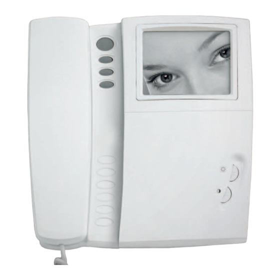
telaio (fig. 19). Nel caso di impianti dove può insorgere VIDEOCITOFONO YVL200 Morsettiera D (collegamento con cavo coassiale) l’effetto Larsen, il microfono può essere montato in 3 segnale video posizione remota, come indicato nelle figure 20 e 21. Funzione dei morsetti (fig. 44) 4 schermo segnale video Applicare il microcontatto (in basso a destra) nell’apposita Morsettiera M1... - Page 4 tach them from the power supply and do not tamper with - infrared LED for lighting the caller; • Tempo di attivazione dell’elettroserratura: regolabile da 1 s a 15 s. Compatibilità con elettroserratura del tipo them. - two potentiometers for the following functions (fig. 5): •...
-
Page 5: Instructions For Connection
Remove the connector (fig. 9) and install the video entry VA/200 POWER SUPPLIER VA/200 POWER SUPPLIER control as shown in figures 10, 11. The unit can be installed without terminal covers, in boxes Function of each terminal, figure 6 For even more secure fastening, remove the receiver fitted with DIN guide (EN 50022). - Page 6 ENTRY PANEL HPV/1 • Vor der Wechsel-/Videosprechanlage muss ein all- Außenstation oder des Aufnahmegeräts über den • Max. switching capacity of the micro-contact: 24V 1A. poliger Netzschalter mit einer Kontakttrennung von Bildschirm auf sequentielle Weise. • Current demand of the lighting module: 40mA, 17.5V. mindestens 3 mm installiert werden.
- Page 7 5 - Mithörschutz. UP - Kasten HBP (zu 3 Modulen oder rund (Ø 65 mm) in 20 Anrufeingänge von Etagen Die Einheit steuert den Mithör- und Mitsehschutz bei angemessener Höhe bündig zur Mauer hineinmauern. Funktion der Steckverbinder Einsatz des Monitors und Sprechgarnituren (Serie 200, Bei einer Außenstation für Videosprechanlagen muß...
- Page 8 Die Ursachen, die den Schutz auslösten, herausfinden und INSTRUCTIONS POUR L’ EMPLOI Commande auxiliaire centralisée (minuterie, sélec- behenden. ET L’ INSTALLATION tion du poste extérieur) ( Luminosité TECHNISCHE DATEN KIT PORTIER VIDÉO MAISON PARTICULIÈRE Contraste EXPANDIBLE BLANC/NOIR POUR SYSTÈME 200 VIDEOSPRECHANLAGE YL200 ) On peut transmettre, à...
-
Page 9: Instructions Pour Le Montage
2 - Dèsactivation de l’installation Introduire le groupe audio-vidéo en haut, à côté de ISTRUCTIONS POUR LA CONNEXION L’installation se dèsactive au terme de la temporisation ou l’embout du châssis (fig. 19). au terme de l’alimentation de la gâche électrique. En cas d’installation où... - Page 10 Bornier C • Durée d’activation de l’installation: 30 s. Lorsqu’on • En caso de avería y/o funcionamiento defectuoso de 5 – 17,5V alimentation soulève le récepteur du poste intérieur, le période los aparatos, desconéctelos de la alimentación eléctrica y 6 + moniteur et accessoires d’activation est prolongée de 30 s jusqu’à...
- Page 11 En la placa es posible instalar otro pulsador más; para de foco fijo (para las dimensiones de la zona de captación INSTRUCCIONES PARA EL MONTAJE hacer referencia a la fig. 4); montarlo seguir las instrucciones que acompañan al proprio pulsador. Para escribir los datos que se desea - grupo fónico (el micrófono es removible para poder VIDEOPORTERO YVL200 en el letrerito de identificación, retirar el sujeta-letrero y...
- Page 12 ) Bornes a utilizar cuando la señal de vídeo es transmi- • Sensor: CCD 1/4”. INSTRUÇÕES PARA O USO tida a través de cable coaxial. • Frecuencia horizontal: 15.625 Hz (15.750 Hz EIA). E INSTALAÇÃO • Frecuencia vertical: 50 Hz (60 Hz EIA). Funciones del puente SW1 (fig.
- Page 13 3 - Nota de chamada e fixar o chassis através dos dois parafusos em dotação Comando auxiliar centralizado (luz escadas, selec- A unidade dispõe de dois geradores de chamada de nota (figura 24). ção da placa botoneira) ( de dois tons diferenciada. O primeiro gerador (borne 8), Efectuar as ligações e bloquear os cabos utilizando a Luminosidade activa-se a cada chamada efectuada da placa botoneira,...
-
Page 14: Características Técnicas
Se a linha coxial não avança, ligar uma resistência de 75Ω NOTA. A protecção do aparelho contra as sobrecargas e A eliminação da aparelhagem deve ser efectuada (roxo, verde, preto, ouro) entre os bornes 3 e 4. curtos-cicuitos obtém-se mediante um interruptor térmico respeitando as normas vigentes e privilegiando a reciclagem das suas partes constituintes. - Page 15 YVL200 VA/200...
- Page 19 43,5 64,5...
- Page 20 LYNEAKIT/22 YVL200 ATTENZIONE! Gli apparecchi che compongono il kit possono essere utilizzati singolarmente per realizzare impianti plurifamiliari. Per la sezione dei conduttori vedere le istruzioni del posto esterno. WARNING! The units included in this kit can also be used individually to realize multi-family installations.
Need help?
Do you have a question about the LYNEAKIT/22 and is the answer not in the manual?
Questions and answers