
Related Manuals for Taktomat RTX Series


Summary of Contents for Taktomat RTX Series
- Page 1 Rotary indexer Type RTX Version 1.0.0 | Original operating instructions 14.06.2021...
-
Page 2: Table Of Contents
Operating instructions Table of contents Table of contents About these Operating Instructions ................3 Further documentation ....................... 5 Excerpt of Declaration of Incorporation ..................6 Safety information....................7 Explanation of the symbols used ....................7 Intended use ..........................8 Foreseeable misuse ........................9 Directives, statutory provisions and standards ................. -
Page 3: About These Operating Instructions
Operating instructions About these Operating Instructions About these Operating Instructions These Operating Instructions describe the partly completed machinery Rotary indexer. The Rotary indexer is referred to below as the partly completed machinery. The Operating Instructions are intended to help you to: •... - Page 4 Operating instructions About these Operating Instructions Manufacturer TAKTOMAT GmbH Rudolf-Diesel-Straße 14 D-86554 Pöttmes Tel: +49 (0) 8253-9965-0 Fax: +49 (0) 8253-9965-50 E-Mail: info@taktomat.de Internet: http://www.taktomat.de/ Technical information The technical information, figures and data contained in these Operating Instructions are correct at the time of printing.
-
Page 5: Further Documentation
Operating instructions About these Operating Instructions Further documentation Please read the following documents according to the provided products before you operate the incomplete machine with these operating instructions. Description Manufacturer Version / Revision / Number Date Assembly and operating instructions gearbox Operating instructions engines Operating instructions sensors Operating instructions encoders... -
Page 6: Excerpt Of Declaration Of Incorporation
Operating instructions About these Operating Instructions Excerpt of Declaration of Incorporation Version 1.0.0 Page 6 of 35 Rotary indexer RTX... -
Page 7: Safety Information
Operating instructions Safety information Safety information General information This document contains important information on the safe use of the partly completed machinery. This information is intended to ensure personal safety and prevent damage to the partly completed machinery. The information is intended for the operator and for properly trained, qualified and instructed staff responsible for operating and servicing the partly completed machinery. -
Page 8: Intended Use
Operating instructions Safety information 2.1.2 MANDATORY SIGNS REFER TO INSTRUCTION MANUAL/BOOKLET! This symbol signifies that the instruction manual/booklet of the component supplier must be read. WEAR HEAD PROTECTION! This symbol signifies that head protection must be worn. WEAR EYE PROTECTION! This symbol signifies that eye protection must be worn. -
Page 9: Foreseeable Misuse
Operating instructions Safety information Foreseeable misuse Any use beyond or other than the intended use is regarded as misuse. 2.3.1 Guarantee conditions Changes to the structure of the materials used in the machine, e.g. the drilling of additional holes, can result in damage to the components. -
Page 10: Responsibility Of The Operator
Operating instructions Safety information Responsibility of the operator The partly completed machinery is to be used commercially according to its intended use. The operator of the partly completed machinery is therefore subject to statutory occupational health and safety provisions. In addition to the general safety information contained in this document, any further safety, accident prevention and environmental regulations applicable to the field of application of the partly completed machinery must also be observed. -
Page 11: Staff Qualification
Service, repair and maintenance work on the partly completed machinery may only be carried out by service engineers of the manufacturer or by qualified staff authorized by Taktomat GmbH. When carrying out such work, always cordon off the working area carefully! Page 11 of 35 Version 1.0.0... -
Page 12: Personal Protective Equipment
Operating instructions Safety information Personal protective equipment Personal protective equipment is intended to protect individuals from safety and health risks at work. When performing certain tasks on and with the partly completed machinery, staff must wear personal protective equipment. This is explicitly indicated in the relevant sections of these Operating Instructions. WARNING Risk of injury from moving parts! Exposed jewellery and long hair can be trapped by moving parts and lead to serious injury. -
Page 13: 2.10 Nameplate
Operating instructions Safety information 2.10 Nameplate Fig. 1 Example of a nameplate There is a nameplate attached to the partly completed machinery: Fig. 2 Position Nameplate ( Page 13 of 35 Version 1.0.0 Rotary indexer RTX... -
Page 14: Construction And Function
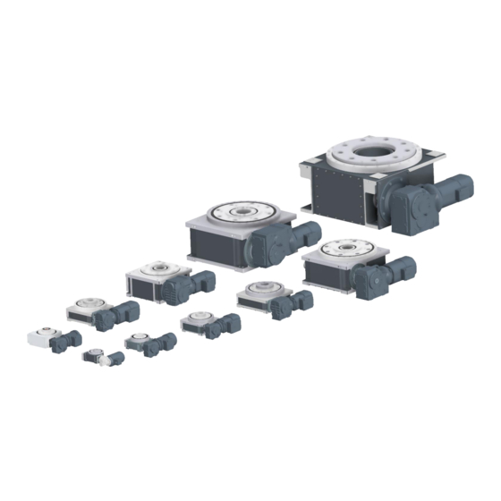
Operating instructions Construction and function Construction and function Construction Rotary indexer type RTX 3.1.1 Rotary indexer RTX350 – RTX900 Fig. 3 Rotary indexer Rotary indexer type RTX closed circuit Fig. 4 Distance design Rotary indexer type RTX closed circuit Pos. Description Indexing ring / output flange (output) Drive... -
Page 15: Function
Operating instructions Construction and function Function The drive (2) drives the indexing ring / output flange (1) via the input shaft (3) through the drum cam. The output plane is offset by 90° to the drive plane. A uniform radial motion is converted on the input side into a clocked or uniformly reduced output motion. -
Page 16: Operating Modes
This operating mode is often used in fast-running systems with short machining times. The incomplete machine is mechanically synchronized to the rest of the system via the free drive shaft. The ratio between cogging and stepping time can be adjusted within certain limits by TAKTOMAT during cam production. -
Page 17: Technical Data Rotary Indexer
Deviating ambient conditions can cause material damage. Do not operate in deviating ambient conditions. Adhere to the given operating – and storage conditions. Other ambient condition only in consultation with TAKTOMAT. 3.5.1 Operating conditions Area of application Inside Temperature range [°C]... -
Page 18: Transport
Operating instructions Transport Transport Safety information NOTICE Damage arising from improper transport! Improper transport can cause significant damage to property. Take care and take note of the symbols on the packaging when unloading the partly completed machinery on delivery and when transporting it on the premises. Transport inspection Immediately on receipt, check to make certain that the delivery is complete and has not been damaged during transport. - Page 19 Operating instructions Transport 4.2.1 Transport using sling equipment Staff Protective equipment Qualified staff The sling equipment (see figure) must be attached to the attachment points (see table and dimensions sheet) in the positions shown in the figure and checked to ensure that it is working correctly (see the instructions for the sling equipment).
- Page 20 Operating instructions Transport Lifting instructions: The angle between the perpendicular and the sling chain must lie between 0° and 45°. WARNING Risk of injury from falling or sinking load! Too weak dimensioned sling equipment can break. Transport vehicles can fail or topple if they are not designed for the weight of the partly completed machinery.
- Page 21 Operating instructions Transport Table for attachment points: Suitable threaded holes are provided on the machine to accommodate slinging equipment. Please refer to the dimensions sheet in the technical data for the thread sizes. Recommendation sling equipment: Thread size Number of sling points Recommendation sling equipment VRS-F...
-
Page 22: Mechanical Installation
Operating instructions Mechanical installation Mechanical installation Installation orientation Possible Installation orientations 1SL90 1SL180 2SL90 2SL180 1SR270 2SR180 2SR270 1SR180 Fig. 7 Possible drive Installation orientation of RTX NOTICE Damage arising from improper installation of the drive! Improper installation of the drive can cause significant damage to property and material. ... -
Page 23: Assembly Of Drive
Qualified staff The drive must be secured with bolts at the specified points. The type of drive, servo motor or asynchronous motor has to be agreed by TAKTOMAT. The slings (see figure) are to be mounted in the threaded holes (see dimension sheet) as positioned in the figure, tightened with torque and checked for correct tightening torque. -
Page 24: Installation And Commissioning
Operating instructions Mechanical installation Installation and commissioning 5.3.1 Safety information DANGER Risk of death by electrocution! There is an immediate risk of fatal injury due to electric shock if live components are touched. Damage to the insulation or to individual components can cause fatal injury. ... - Page 25 Maximum weight moved (as per TAKTOMAT project planning). Minimum positioning time (as per TAKTOMAT project planning). Maximum overhang (tipping moment) (as per TAKTOMAT project planning). Maximum tightening torque for securing holes, see torque table. Page 25 of 35 Version 1.0.0...
-
Page 26: Guidelines For Drive Control Of Rotary Indexers
Operating instructions Mechanical installation Guidelines for drive control of rotary indexers The switching time is calculated when designing rotary indexers. The switching time is the time required to move the output flange from the station to the station (switching) at the constant rated motor speed (50 Hz). The switching time does not include times for motor movement in the cogging range, as well as the time for motor acceleration and deceleration. - Page 27 Operating instructions Mechanical installation The switching range of the output flange is shown in the figure below. Correspondingly, the figure shows the switching range of the cam, which corresponds to the milled off area of the cam. Example: Rotary indexer, 4 stations (90°), switching time 0.8 s, switching angle 300°, cogging range 60° Output flange 90°...
- Page 28 Operating instructions Mechanical installation The acceleration and deceleration time of the motor depends on many parameters and especially on how the motor and the brake are controlled. As a result, the start-up time or the stopping time of the motor can vary greatly. If the motor is not optimally controlled, the stopping time can be so high that the motor can no longer stop in the cogging range and overruns the cogging range.
-
Page 29: Maintenance Task
Operating instructions Mechanical installation Maintenance task 5.5.1 Maintenance plan Maintenance activity Staff Interval Daily General visual and noise check Operator Monthly Check rotary indexer RTX for leaking oil Operator • Visual inspection for damage • Remove dust deposits (especially on the ventilation Semi-annual Qualified staff grille of the drive unit). -
Page 30: Lubrication
Operating instructions Mechanical installation Lubrication 5.6.1 Requirements for lubricants General To ensure safe operation and a long service life, it is necessary to lubricate the machine carefully. The specified oil and grease must be applied to all lubrication points. Carefully clean dirty lubrication points using a suitable agent and then lubricate them with new lubricant. After lubrication, any excess lubricant must be removed and properly disposed of. -
Page 31: Faults
Check sensor setting on position cams • Brake not open Check sensor cable on sensor Motor rotates, but • External gear defective Call TAKTOMAT GmbH drum cam table Remove external blockage / engage • Friction clutch disengages does not rotate safety clutch and roller star / ... - Page 32 Operating instructions Faults Fault Possible cause Remedy Sensor does not • Remove blockage Sensor not actuated / sensor send signal actuated Check cable and replace if necessary • Cable defective Replace sensor • Sensor defective Check voltage •...
-
Page 33: Disposal
Operating instructions Disposal Disposal WARNING Risk of environmental damage caused by improper disposal! Improper disposal of components can cause environmental damage to persons and environment. Disposal of the components in accordance with the applicable local rules Environmentally compatible disposal of auxiliary substances such as chemicals, paints, acids, alkalis, adhesives Essentially components of the machine consists of following materials: copper (drive unit, electrical lines) Steel, aluminium and grey cast iron (housing, structures, shaft,... -
Page 34: Spare Parts And Wear Parts For Rotary Indexers
Spare and wear parts for the TAKTOMAT rotary indexer are always order-specific. Please contact TAKTOMAT for a list of spare and wear parts for the rotary indexer. To speed up the ordering process for spare and wear parts we need the following data of the gearbox, which you will find on the nameplate: Serial number (see chapter nameplate). -
Page 35: Annex
Operating instructions Annex Annex Safety data sheets Designation EP 2 Grease Data Sheet HI MOBILGEAR 600 XP 460 Page 35 of 35 Version 1.0.0 Rotary indexer RTX...
Need help?
Do you have a question about the RTX Series and is the answer not in the manual?
Questions and answers