Table of Contents
Advertisement
Quick Links
Advertisement
Table of Contents

Subscribe to Our Youtube Channel
Related Manuals for Taktomat TMF Series


Summary of Contents for Taktomat TMF Series
- Page 1 Rotary indexer Version 1.0 Assembly instructions 2022-04-25...
-
Page 2: Table Of Contents
Assembly instructions Table of contents About these instructions ................................. 3 Purpose ........................................3 Contact information ....................................3 Product designation ....................................3 Symbols ......................................... 4 Safety ........................................5 Safety instructions ....................................5 Warnings ....................................... 5 Requirements for personnel ................................. 7 Personal protective equipment ................................7 Requirements for incorporation into a complete machine ......................... -
Page 3: About These Instructions
Purpose The purpose of these Assembly Instructions is to provide users with all the information necessary for proper and safe installation of the rotary indexer in a complete machine. Contact information TAKTOMAT GmbH Rudolf-Diesel-Straße 14 86554 Pöttmes Tel.: +49 (0) 8253-9965-0... -
Page 4: Symbols
Assembly instructions About these instructions Symbols The following symbols are used in these instructions: Instructions and directions Requirements for performing an instruction are indicated by a check mark. The action steps to be executed are numbered. The results of individual action steps are indicated by a black arrow. The overall result of an instruction is marked by a white arrow in a black circle. -
Page 5: Safety
Assembly instructions Safety Safety Safety instructions General safety instructions • Read through these instructions completely • Observe the information and instructions in these instructions • Keep unauthorized persons away from the working area • Work on electrical systems may only be carried out by qualified electricians •... - Page 6 Assembly instructions Safety 2.2.2 Meaning of the signal words and symbols The following signal words are used in this document: Signal word Meaning DANGER Indicates a hazardous situation which will result in death or serious injury. WARNING Indicates a potentially hazardous situation which may result in death or serious injury. CAUTION Indicates a potentially hazardous situation which may result in minor or moderate injury.
-
Page 7: Requirements For Personnel
Assembly instructions Safety Requirements for personnel The activities described in these instructions may only be performed by qualified personnel. Qualified personnel are persons who are able to carry out the work assigned to them due to their technical training, knowledge and experience. -
Page 8: Product Description
All applications deviating from this intended use are not permitted. • Modifications must be approved by TAKTOMAT • The rotary indexer may only be operated within the defined operating parameters • Use of the rotary indexer in the food sector is not permitted Technical data 3.2.1... - Page 9 Assembly instructions Product description 3.2.3 Dimensions TMF350 Roll star / output flange Ø [mm] Overall height (roll star mounting surface) [mm] Internal diameter Ø [mm] Internal transmission ratio [i] Precision of absolute positioning in angular seconds [ " ] ± 6 Precision of relative positioning in angular seconds [ "...
- Page 10 Assembly instructions Product description TMF2000 Roll star / output flange Ø [mm] Overall height (roll star mounting surface) [mm] Internal diameter Ø [mm] Internal transmission ratio [i] Indexing accuracy in angular seconds [ " ] Length Width Height [mm] 688.5 ...
- Page 11 Assembly instructions Product description TMF4000 Roll star / output flange Ø [mm] 1030 Overall height (roll star mounting surface / output flange) [mm] Internal diameter Ø [mm] Internal transmission ratio [i] Indexing accuracy in angular seconds [ " ] Length Width Height [mm] 1055 ...
- Page 12 Assembly instructions Product description TMF8000 Roll star / output flange Ø [mm] 2300 Overall height (roll star mounting surface / output flange) [mm] Internal diameter Ø [mm] 1520 Internal transmission ratio [i] Indexing accuracy in angular seconds [ " ] Length ...
-
Page 13: Product Overview
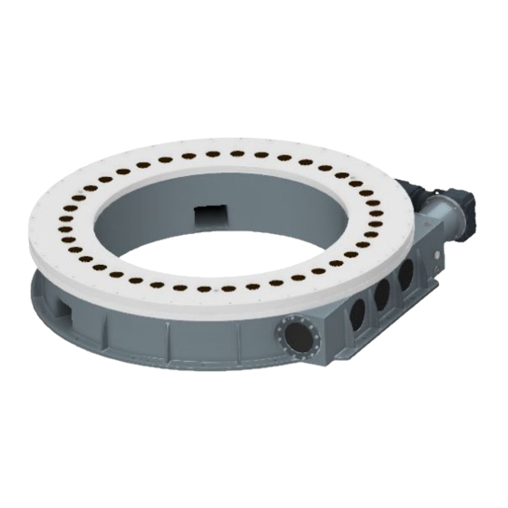
Assembly instructions Product description Product overview 3.3.1 TMF350 Fig. 2: Rotary indexer structure: TMF350 Housing Roll star (output) Fixing hole Ø 6H7 (2x) Mounting hole for M10 (4x) Input shaft (drive) 3.3.2 TMF850-2000 Fig. 3: Rotary indexer structure: TMF850 – TMF2000 Roll star / output flange (output) Input shaft (drive) Housing... - Page 14 Assembly instructions Product description 3.3.3 TMF3000-5000 Fig. 4: Rotary indexer structure: TMF3000 – TMF5000 Roll star / output flange (output) Drive unit Input shaft (drive) Housing Position indicator Grease nipple Vernier Cable aperture Service apertures Oil sight glass Oil drain plug 14 / 35 Rotary indexer TMF Version 1.0...
- Page 15 Assembly instructions Product description 3.3.4 TMF8000 Fig. 5: Rotary indexer structure: TMF8000 Cable aperture (2x) Roll star (output) Oil filler plug Input shaft (drive) Oil sight glass Oil drain plug Housing Threaded hole M36 (3x) for eyebolt Mounting hole Ø 26 (15x) Fixing hole Ø16H7 (2x) Version 1.0 Rotary indexer TMF...
-
Page 16: Transport
Assembly instructions Transport Transport Required personal protective equipment WARNING Tipping or falling loads Suspended loads can tip or fall down. This can cause serious or fatal injuries to persons. • Do not step under suspended loads • Keep unauthorized persons out of the danger zone •... -
Page 17: Transport With Slings
Assembly instructions Transport Transport with slings Attach the slings at the attachment points as shown below and make sure they are functioning properly. The angle between the vertical and the chain sling or sling strap must be between 0 and 45°. Fig. -
Page 18: Assembly
Damage to components Improper attachment of the drive can cause material damage • The type of drive, e.g. a servomotor or three-phase a.c. motor must be agreed with TAKTOMAT • On attaching the drive, note and follow the manufacturer’s operating instructions •... - Page 19 Assembly instructions Assembly Recommended tools The tools are not included in the standard scope of supply. They must be ordered from TAKTOMAT separately. Quantit Type Clearance hole Designation Size Item no. Assembly screw Drive flange Ø 9 mm ART00332104 TMF1000...
- Page 20 Assembly instructions Assembly Mounting the complete drive on the rotary indexer Fig. 10: Mounting the complete drive on the rotary indexer Complete drive with cast flange Nut DIN 939 with lock washer, Type S (8x) Stud DIN 939 (8x) Rotary indexer Attach the complete drive to the rotary indexer as follows: ...
- Page 21 Assembly instructions Assembly 5.2.2 Attachment with flange plate Mounting the flange plate on the complete drive Fig. 11: Mounting the flange plate on the complete drive Complete drive Flange plate Cylinder head screw EN ISO 4762 Assembly screw (2x) with lock washer, Type S (8x) Mount the flange plate on the complete drive as follows: 1.
- Page 22 Assembly instructions Assembly Mounting the complete drive on the rotary indexer Fig. 12: Mounting the complete drive on the rotary indexer Complete drive Hexagon socket head cap screw EN ISO 4762 with lock washer, Type S (4x) Cylinder head screw EN ISO 4762 Assembly screw (2x) with lock washer, Type S (8x) Flange plate...
- Page 23 Assembly instructions Assembly 5.2.3 TMF8000 attachment Fig. 13: TMF8000 attachment Screw M12 DIN 933 with lock washer S12 Complete drive Spigot Ø230 Housing TMF8000 Assemble the complete drive as follows: 1. Push the complete drive (2) onto the drive shaft, until it is positioned flush on the spigot (3). 2.
-
Page 24: Installation
Note the following regarding attachments on the roll star / output flange: • Maximum weight moved (according to TAKTOMAT project planning). • Minimum time until positioning (according to TAKTOMAT project planning). • Maximum overhang (tipping moment) (according to TAKTOMAT project planning). -
Page 25: Operation
The cylinder is unable to accelerate and decelerate the accumulated load gently. As a result, high accelerations occur, which impact the mechanics. Inching may only be carried out with a suitable universal controller. A suitable controller is, for example, the TIC controller (TAKTOMAT Indexing Controller). Emergency stop The emergency stop stops the movement of the roll star / output flange immediately. -
Page 26: Maintenance
Assembly instructions Maintenance Maintenance Required personal protective equipment CAUTION Harmful substances Lubricants can cause health damage • When using lubricants, note the information in the safety data sheets Maintenance work 7.1.1 Maintenance plan Interval Activity Personnel Daily Operator • General visual inspection and check for noises Monthly Operator •... - Page 27 Assembly instructions Maintenance 7.1.2 Checking the oil level NOTICE Damage to components Improper refilling of the lubricant can cause material damage. • Before checking the oil level, the rotary indexer must stand still for at least 30 minutes • Check the oil level only when the indexer is at a standstill •...
-
Page 28: Lubricating
Assembly instructions Maintenance Lubricating 7.2.1 Lubricant requirements General Careful lubrication is necessary to ensure operating reliability and a long life of the partly completed machinery. All lubricating points must be supplied with the specified oils and greases. Clean soiled lubricating points carefully with petroleum or an appropriate means and then lubricate with new lubricant. After lubricating, the surplus lubricant must be removed and disposed of properly. -
Page 29: Replacing The Cam Follower
Assembly instructions Maintenance Overview of relubrication quantities for TMF series with grease nipple Product Divide the relubrication quantity between the respective number of grease nipples TMF3000 26 g TMF4000 34 g TMF5000 49 g TMF8000 128 g Replacing the cam follower... - Page 30 Retaining ring Hexagon head screw Schnorr lock washer Washer Roll sleeve TKR Taktomat cam follower 7.3.1 Dismantling the cam follower 1. Remove the cap plug (2) with a double hook. 2. Remove the retaining ring (3) with retaining ring pliers.
- Page 31 Assembly instructions Maintenance 7.3.2 Installing the cam follower NOTICE Note the specified tightening torques • Tighten all screw connections to the specified/standardised torque 1. Heat the roll sleeve (7) to make the cam follower (8) easy to press in. 2. Press the cam follower (8) into the roll sleeve (7) up to the limit stop. 3.
-
Page 32: Troubleshooting
• Safety clutch overload / disengaged engage the safety clutch roll star / output flange has • Input shaft is broken • Contact TAKTOMAT GmbH no clearance • Cam follower ripped off by large • Contact TAKTOMAT GmbH The drive turns but the rotary... -
Page 33: Disposal
Assembly instructions Disposal Disposal Required personal protective equipment NOTICE Environmental damage Improper disposal may result in environmental damage • Dispose of components and operating materials in accordance with local regulations • Observe the safety data sheets of the operating materials Materials used The components are mainly made of the following materials: •... -
Page 34: Spare And Wear Parts
• Check spare parts for faults or defects prior to installation Spare and wear parts are always order-specific. A corresponding spare and wear parts list is available from TAKTOMAT on request. When ordering spare parts, always specify the serial number. The serial number is located on the nameplate. -
Page 35: Annexes
(The original declaration of incorporation is included in the documentation) Translation of the original declaration of incorporation (in German) for partly completed machinery (Machinery Directive 2006/42/EC, Annex II 1 B) Manufacturer: TAKTOMAT GmbH Rudolf-Diesel-Straße 14 D-86554 Pöttmes Description and identification of the partly completed machinery: Your order No.: Our order No.:...
Need help?
Do you have a question about the TMF Series and is the answer not in the manual?
Questions and answers