Rf-t CR2 Manual
Circular fire damper for large diameters
Hide thumbs
Also See for CR2:
- Manual (40 pages) ,
- Quick start manual (2 pages) ,
- Product manual (50 pages)
Table of Contents
Advertisement
Quick Links
CR2
Circular fire damper for large diameters
Clapets coupe-feu et
0749
Volets de désenfumage D.A.S.
Organisme Certificateur
AFNOR Certification - www.marque-nf.com
www.rft.be
Rf-Technologies nv Lange Ambachtstraat 40 9860 Oosterzele Belgium Tel +32 9 362 31 71 Fax +32 9 362 33 07 info@rft.be
Advertisement
Table of Contents

Subscribe to Our Youtube Channel
Related Manuals for Rf-t CR2


Summary of Contents for Rf-t CR2
- Page 1 Circular fire damper for large diameters Clapets coupe-feu et 0749 Volets de désenfumage D.A.S. Organisme Certificateur AFNOR Certification - www.marque-nf.com www.rft.be Rf-Technologies nv Lange Ambachtstraat 40 9860 Oosterzele Belgium Tel +32 9 362 31 71 Fax +32 9 362 33 07 info@rft.be...
-
Page 2: Table Of Contents
Table of content Table of content Declaration of performance Product presentation CR2 Range and dimensions CR2 Evolution - kits Options - at the time of order Storage and handling Installation Installation at a minimal distance from another damper or from an adjacent supporting construction... -
Page 3: Declaration Of Performance
Declaration of performance Harmonised standard EN 15650:2010... -
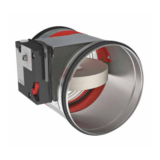
Page 4: Product Presentation Cr2
5. blade bumper 6. intumescent strip 7. fusible link 8. rubber sealing ring 9. product identification Range and dimensions CR2 Exceeding blade: X = on the mechanism side, Y = on the wall side ØDn [mm] ØDn [mm] 200 250... -
Page 5: Evolution - Kits
Evolution - kits Ø Dn < 315 mm Ø Dn < 315 mm ØDn ØDn CFTH BFL(T) UNIQ CFTH BFL(T) BFN(T) UNIQ Evolution - kits Automatic unlocking mechanism CFTH with FCU and without FTH 72 KITS CFTH Upgradeable automatically unlocking mechanism KITS MANO EVO Spring return actuator BFL 24V KITS BFL24... - Page 6 Evolution - kits Spring return actuator BFL 230V KITS BFL230 Spring return actuator BFL 230V with thermo-electric fuse (T) KITS BFLT230 Spring return actuator BFN 24V (BFN kits must be used instead of BFL kits for fire dampers KITS BFN24 produced before 1/7/2015) Spring return actuator BFN 24V KITS BFN24...
- Page 7 Evolution - kits Spring return actuator BF 24V (BF kits must be used instead of BFN kits for fire dampers KITS BF24 produced before 1/7/2015) Spring return actuator ONE 24V (with fusible link T) + unipolar beginning- and end-of-ran- KITS ONE T 24 FDCU ge switch Spring return actuator ONE 24V (with fusible link T) + bipolar beginning- and end-of-ran- KITS ONE T 24 FDCB...
- Page 8 Evolution - kits Electromagnet 48 V DC + FDCU KITS VM48 MAN EVO FDCU 1 Beginning or end of range switch FCU/DCU/FCB/DCB KITS FDC CFTH Unipolar beginning and end of range switch KITS FDCU MAN Bipolar beginning and end of range switch KITS FDCB MAN Bipolar beginning and end of range switch KITS SN2 BFL/BFN...
-
Page 9: Options - At The Time Of Order
Testbox for mechanisms 24/48 V (magnet, motor, beginning and end of range switches) MECT Kit with 4 cover plates (gypsum plasterboard 12.5 mm) for CR2 in light wall. EPP CR2 Sturdy digital endoscope for the internal inspection of fire dampers through an optional inspection opening. -
Page 10: Storage And Handling
The air tightness class will be maintained if the damper is installed according to the installation manual. ∎ Rf-t fire dampers are always tested in standardised constructions according to EN 1366-2. The achieved results are valid for similar supporting constructions with a fire resistance, thickness and density equal or superior to the supporting construction used during the test. -
Page 11: Installation
200 mm from another damper, unless the solution was compliant with existing classifications (Declaration of Perfor- tested at a shorter distance. This range of Rf-t fire dampers has mance). A. Sealing of the opening at the side with minimal... -
Page 12: Installation In Rigid Wall And Floor
Installation Installation in rigid wall and floor The product was tested and approved in: Range Wall type Sealing Classification Ø 200-630 mm Rigid wall Aerated concrete ≥ 100mm Mortar / Gypsum EI 120 (v i n o) S - (500 Pa) Ø... -
Page 13: Installation In Flexible Wall (Metal Stud Gypsum Plasterboard Wall)
Installation ≥150kg/m³ Gips / Mortel Mortel 5. Mount the dampers in the opening. 6. Seal the rest of the opening with standard mortar or gypsum Apply rigid stone wool panels (150 kg/m³) to a depth of 400 (only for vertical walls). mm (150 mm on each side of the wall) to seal the opening at the side with minimal distances. - Page 14 Installation TEST! JointFiller ≥ 40kg/m³ ≥ 30 ≥ 30 25mm ≥ 30 < 200mm ≥ 40kg/m³ ≥ 30 40mm ≤ 600mm 2x12.5 / 1x25mm 5. The dampers can be installed at a minimum distance (≥ 30 6. Build the drywall and foresee horizontal and vertical studs mm) from an adjacent wall or from another damper.
- Page 15 Installation ≥150kg/m³ ≥ 40kg/m³ 7. Mount the dampers in the opening. 8. Seal the rest of the opening with standard stone wool 40 kg/ Apply rigid stone wool panels (150 kg/m³) to a depth of 400 m³ across the entire wall thickness. mm (150 mm on each side of the wall) to seal the opening at the side with minimal distances.
- Page 16 Installation ≤ 600mm ≥ 40kg/m³ ØDn+ 80 mm Gips ØDn+ 80 mm ØDn+80mm 2x12.5 / 1x25mm ≥ 30 ≥ 30 60-80mm ≥ 30 < 200mm ≥ 40kg/m³ ≥ 30 40mm ≤ 600mm 2x12.5 / 1x25mm 3. The dampers can be installed at a minimum distance (≥ 30 4.
-
Page 17: Installation In Gypsum Block Wall
Installation ≥150kg/m³ 5. Mount the dampers in the opening. 6. Seal the rest of the opening (40 mm) with standard gypsum Apply rigid stone wool panels (150 kg/m³) to a depth of 400 across the entire wall thickness. mm (150 mm on each side of the wall) to seal the opening at the side with minimal distances. - Page 18 Installation ≥ 30 ≥ 30 ≥ 30 < 200mm ≥70 3. The dampers can be installed at a minimum distance from an 4. Make the necessary openings (Dn + 80 mm) in the wall. adjacent wall or from another damper. ≥150kg/m³...
- Page 19 Installation ≤ ØDn+600 ≤ 300 ≤ 300 ≤ ØDn+600 A (EN520) 60’ F (EN520) 90’ 150kg/m³ PROMASTOP-E / CC 2x12.5 / 1x25mm PROMASTOP-CB 50 (CC) HILTI CFS-S ACR 90’ / HILTI CFS-CT B 100mm ≥ 40kg/m³ 1. The opening around the damper is sealed with 2 layers of 50 mm-thick mineral wool panels with fire resistant coating on one side (type PROMASTOP-CB 50 / PROMASTOP-CB/CC 50 / HILTI CFS-CT B).
- Page 20 Installation ≤ Øn+600 ≥ 30 ≤ 300 ≥ 30 ≤ 400 ≥ 30 ≤ Øn+600 ≤ 300mm < 200mm ≤ 600mm Promat : HxW ≤3,75m² ≤ 300 40mm Hilti EI90: HxW ≤3,20m² Hilti EI120: HxW ≤1,44m² ≤ 400 7. The damper does not need to be centered in the opening 8.
- Page 21 Installation ≥150kg/m³ 150kg/m³ PROMASTOP-E / CC PROMASTOP-CB 50 (CC) HILTI CFS-S ACR / HILTI CFS-CT B 11. Apply rigid stone wool panels (150 kg/m³) to a depth of 400 12. Seal the rest of the opening with 2 layers of 50 mm-thick mm (150 mm on each side of the wall) to seal the opening at coated rigid mineral wool panels (see above).
- Page 22 Installation ≤ 300 ≤ 300 ≤ ØDn+600 ≤ ØDn+600 150kg/m³ PROMASTOP-E / CC PROMASTOP-CB 50 (CC) HILTI CFS-S ACR / HILTI CFS-CT B 1. The opening around the damper is sealed with 2 layers of 50 mm-thick mineral wool panels with fire resistant coating on one side (type PROMASTOP-CB 50 / PROMASTOP-CB/CC 50 / HILTI CFS-CT B).
-
Page 23: Inspection Of The Damper
1. Remove the air-tight plug from the damper. 2. Insert the camera of the endoscope (for example Inspecam Rf-t) through the opening and inspect the inside of the damper. 3. After inspection, replace the air-tight plug thoroughly on the damper opening. The position is crucial in order to maintain the air-tightness of the fire damper. -
Page 24: Operation And Mechanisms
ONE Spring return actuator for remote control The spring-return actuator ONE is designed to easily operate Rf-t fire dampers of all sizes, automatically or remotely.Five models are available, 24 or 230 volt, with FDCU or FDCB position switches; and 24 volt with plug (ST). - Page 25 UNIQ Upgradeable operating mechanism for remote control Compliant with NF S 61-937, the UNIQ operating mechanism is designed to operate Rf-t fire dampers of all sizes, easily and remotely. Four models are available: with FDCU or FDCB position switches and with or without ME resetting motor. All models are dual-voltage 24/48V and with an electrical impulse triggering (VD) with a possibility to change to power interruption triggering (VM) by removing a jumper.
- Page 26 When connecting the cables, it is necessary to use the cable-ties, as shown in the drawing included in the bag containing the † cable-ties. prod. < 1/7/2015 prod. ≥ 1/7/2015 CR60(1s) CU-LT CR2≤400 CR2>400 CR60(1s) CU-LT CR2≤400 CR2>400 CR120 CU-LT-1s CU2≤1200...
- Page 27 Caution: Do not use a drill or screwing machine. † Stop as soon as the motor is completely rearmed (end of range). † prod. < 1/7/2015 prod. ≥ 1/7/2015 CR60(1s) CU-LT CR2≤400 CR2>400 CR60(1s) CU-LT CR2≤400 CR2>400 CR120 CU-LT-1s CU2≤1200 CU2>1200...
- Page 28 The spring return actuator BFN(T) is specially designed to remotely control fire dampers. The BFN(T) model is intended for fire dam- pers with large dimensions (ø > 400 mm (CR2) or W+H > 1200 mm (CU2, CA2, CU2_15, CU4)) or for dampers CU-LT(-1s), CR60, CR120 with a production date before 1 July 2015.
- Page 29 Operation and mechanisms...
-
Page 30: Electrical Connection
Electrical connection Electrical connection CFTH UNIQ 24/48 VDC VD/VM VD : Spanningspuls ontgrendeling 15 16 (met jumper) VM : Spanningsonderbreking ontgrendeling (zonder jumper) 24VDC DCU : Unipolaire beginloopschakelaar 24VAC FCU : Unipolaire eindeloopschakelaar DCB : Bipolaire beginloopschakelaar 230VAC FCB : Bipolaire eindeloopschakelaar DC : Schakelaar open positie brandklep 24/48 VDC ME : Herwapeningsmotor... - Page 31 Electrical connection MANO EVO BFL(T) BFN(T) <5° <5° <80° <80° 15 16 24 V DC 48 V DC 24/48 V DC +/- 10% 24/48 V AC +/- 10% 24VDC 24VDC 24VAC 24VAC 230VAC 230VAC resetting time running time noise level noise level Protection cable supply / control...
-
Page 32: Weights
16,8 18,8 21,8 24,8 28,8 CR2 + UNIQ ØDn [mm] 11,9 13,9 16,9 18,9 21,9 24,9 28,9 CR2 + MANO EVO ØDn [mm] 11,0 13,0 16,0 18,0 21,0 24,0 28,0 CR2 + BFL ØDn [mm] 11,1 13,1 16,1 CR2 + BFLT ØDn [mm]... -
Page 33: Selection Graphs
Requested Δp= ca. 21 Pa (Cfr. selection graph) LWA= ca. 47 dB(A) Calculation Δp= 2.17 * (4m/s)² * 0.6 = 20.83Pa Selection data CR2 - A-weighted sound power level in the duct ØDn [mm] Sn [m²] 0,0129 0,0253 0,0472 0,0640... -
Page 34: Correction Factor Δl
Correction factor ΔL Correction factor ΔL To obtain the sound power level for the octave midband: LW oct = ΔL + Lwa [Hz] 1000 2000 4000 8000 2 - 4 m/s 6 - 8 m/s 10 - 12 m/s Sample order 450 UNIQ VD/VM ME FDCB product diameter...
Need help?
Do you have a question about the CR2 and is the answer not in the manual?
Questions and answers