Rf-t CR2 Manual
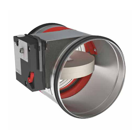
Circular fire damper for large diameter
Hide thumbs
Also See for CR2:
- Manual (34 pages) ,
- Quick start manual (2 pages) ,
- Product manual (50 pages)

Related Manuals for Rf-t CR2


Summary of Contents for Rf-t CR2
- Page 1 Circular fire damper for large diameters 0749 www.rft.be Rf-Technologies nv Lange Ambachtstraat 40 9860 Oosterzele Belgium Tel +32 9 362 31 71 Fax +32 9 362 33 07 info@rft.be...
-
Page 2: Table Of Contents
Table of content Table of content Declaration of performance Product presentation CR2 Range and dimensions CR2 Variant CR2-L500 Range and dimensions CR2-L500 Evolution - kits Options - at the time of order Storage and handling Installation Installation at a minimal distance from another damper or from an adjacent supporting construction... - Page 3 Explanation of the abbreviations and pictograms Explanation of the abbreviations and pictograms Wn = nominal width E.TELE = power supply magnet Sn = free air passage Hn = nominal height E.ALIM = power supply motor ζ [-] = pressure loss coefficient Dn = nominal diameter V = volt Q = airflow...
-
Page 4: Declaration Of Performance
Declaration of performance Harmonised standard EN 15650:2010... -
Page 5: Product Presentation Cr2
7. fusible link 8. rubber sealing ring 9. product identification Range and dimensions CR2 ØDn [mm] 200 250 315 355 400 450 500 560 630 Exceeding blade: X = on the mechanism side, Y = on the wall side ØDn [mm]... -
Page 6: Variant Cr2-L500
Range and dimensions CR2-L500 Variant CR2-L500 CR2 damper with a tunnel casing extension at the wall side to facilitate the connection to the duct when the supporting construction is thicker than 100 mm. 1. casing in galvanised steel 2. damper blade 3. -
Page 7: Evolution - Kits
Evolution - kits Evolution - kits Spring return actuator ONE 24V (with fusible link T) + bipolar beginning- and end-of- KITS ONE T 24 FDCB range switch Spring return actuator ONE 24V (with fusible link T) + unipolar beginning- and end-of- KITS ONE T 24 FDCU range switch Spring return actuator ONE 230V (with fusible link T) + unipolar beginning- and end-of-... - Page 8 Evolution - kits KITS BFL24-ST Spring return actuator BFL 24V with plug (ST) KITS BFLT24 Spring return actuator BFL 24V with thermo-electric fuse (T) KITS BFLT230 Spring return actuator BFL 230V with thermo-electric fuse (T) KITS BFLT24-ST Spring return actuator BFL 24V with thermo-electric fuse (T) and plug (ST) KITS BFN24 Spring return actuator BFN 24V Spring return actuator BFN 24V (BFN kits must be used instead of BFL kits for fire dampers...
- Page 9 Evolution - kits KITS BFNT230 Spring return actuator BFN 230V with thermo-electric fuse (T) KITS BFNT24-ST Spring return actuator BFN 24V with thermo-electric fuse (T) and plug (ST) Spring return actuator BF 24V (BF kits must be used instead of BFN kits for fire dampers KITS BF24 produced before 1/7/2015) KITS FDC CFTH...
-
Page 10: Options - At The Time Of Order
Inspection opening to visually determine the state and the position of the damper, by using an endoscope. EN1751_C Air-tightness class C (note: for CU2 H > 600 or W > 800 / for CR2 Ø > 315). EN 1751 ONE-X CN... -
Page 11: Storage And Handling
The air tightness class will be maintained if the damper is installed according to the installation manual. ∎ Rf-t fire dampers are always tested in standardised constructions according to EN 1366-2. The achieved results are valid for similar supporting constructions with a fire resistance, thickness and density equal or superior to the supporting construction used during the test. -
Page 12: Installation At A Minimal Distance From Another Damper Or From An Adjacent Supporting Construction
2. Certified solution According to the European test standard, a fire damper must For the Rf-t fire dampers, the solution consists of the following be installed at a minimum distance of 75 mm from an adjacent elements: A: Universal sealing for minimal distance; B:... -
Page 13: Installation In A Rigid Wall
Installation Installation in a rigid wall The product was tested and approved in: Range Wall type Sealing Classification Ø 200-630 mm Rigid wall Aerated concrete ≥ 100 mm Mortar / Gypsum EI 120 (v i n o) S - (500 Pa) Ø... - Page 14 Installation ≥150 kg/m³ ≥100 5. Make the necessary openings (≤ Dn + 100 mm) / 6. Mount the dampers in the opening. (≤ Dn + 80 mm) in the wall. Apply rigid stone wool panels (≥ 150 kg/m³) to a depth of 400 mm (150 mm on the mechanism side of the wall) to seal the opening at the side with minimal distances.
-
Page 15: Installation In Rigid Floor
Installation Installation in rigid floor The product was tested and approved in: Range Wall type Sealing Classification Ø 200-630 mm Rigid floor Aerated concrete ≥ 150 mm Mortar EI 120 (h i n o) S - (500 Pa) TEST! 100 mm Mortar ≥... - Page 16 Installation ≥150 kg/m³ Mortar 5. Mount the dampers in the opening. 6. Seal the rest of the opening with standard mortar. Apply rigid stone wool panels (≥ 150 kg/m³) to a depth of 400 mm (150 mm on the mechanism side of the wall) to seal the opening at the side with minimal distances.
-
Page 17: Installation In Flexible Wall (Metal Stud Gypsum Plasterboard Wall)
Installation Installation in flexible wall (metal stud gypsum plasterboard wall) The product was tested and approved in: Range Wall type Sealing Classification Ø 200-630 mm Flexible wall Metal studs gypsum plasterboard Type F (EN 520) ≥ 100 mm Stone wool ≥ 40 kg/m³ + cover plates EI 90 (v i n o) S - (300 Pa) Ø... - Page 18 Installation ≥150 kg/m³ Plaster joint ller 7. Mount the dampers in the opening. 8. Apply cover plates (gypsum plasterboards) to finish the Apply rigid stone wool panels (≥ 150 kg/m³) to a depth of surface at both sides. 400 mm (150 mm on the mechanism side of the wall) to seal Seal off the space between the plasterboards with jointfiller.
-
Page 19: Installation In Flexible Wall (Metal Stud Gypsum Plasterboard Wall), Sealing With Gypsum
Installation Installation in flexible wall (metal stud gypsum plasterboard wall), sealing with gypsum The product was tested and approved in: Range Wall type Sealing Classification Ø 200-630 mm Flexible wall Metal studs gypsum plasterboard Type A (EN 520) ≥ 100 mm Gypsum EI 60 (v i n o) S - (500 Pa) - Page 20 Installation ≥150 kg/m³ Plaster 5. Mount the dampers in the opening. 6. Seal the rest of the opening with standard gypsum across the Apply rigid stone wool panels (≥ 150 kg/m³) to a depth of entire wall thickness. 400 mm (150 mm on the mechanism side of the wall) to seal the opening at the side with minimal distances.
-
Page 21: Installation In Flexible Wall (Metal Stud Gypsum Plasterboard Wall), Sealing With Mortar
Installation Installation in flexible wall (metal stud gypsum plasterboard wall), sealing with mortar The product was tested and approved in: Range Wall type Sealing Classification Ø 200-630 mm Flexible wall Metal studs gypsum plasterboard Type F (EN 520) ≥ 100 mm Mortar EI 90 (v i n o) S - (300 Pa) - Page 22 Installation ≥150 kg/m³ Mortar 5. Mount the dampers in the opening. 6. Seal the rest of the opening with standard mortar across the Apply rigid stone wool panels (≥ 150 kg/m³) to a depth of entire wall thickness. 400 mm (150 mm on the mechanism side of the wall) to seal the opening at the side with minimal distances.
-
Page 23: Installation In Gypsum Block Wall
Installation Installation in gypsum block wall The product was tested and approved in: Range Wall type Sealing Classification Ø 200-630 mm Flexible wall Gypsum blocks ≥ 70 mm Block glue EI 120 (v i n o) S - (500 Pa) TEST! ≤... - Page 24 Installation ≥150 kg/m³ Block glue 5. Mount the dampers in the opening. 6. Seal the rest of the opening with block glue across the entire Apply rigid stone wool panels (≥ 150 kg/m³) to a depth of wall thickness. 400 mm (150 mm on the mechanism side of the wall) to seal the opening at the side with minimal distances.
-
Page 25: Installation In Flexible And Rigid Wall, Sealing With Rigid Rock Wool Boards With Coating
Installation Installation in flexible and rigid wall, sealing with rigid rock wool boards with coating The product was tested and approved in: Range Wall type Sealing Classification Ø 200-630 mm Rigid wall Aerated concrete ≥ 100 mm Stone wool + coating ≥ 140 kg/m³ EI 90 (v i n o) S - (300 Pa) Ø... - Page 26 Installation TEST! TEST! 2x50 mm 2x60 mm F (EN520) 120’ (BELGIUM) ≤ Dn+600 ≥ 30 ≤ 300 ≥ 30 ≤ 400 ≥ 30 ≤ Dn+600 ≤ 300 mm < 200 mm ≤ 625 mm Promat : HxW ≤ 3,75 m² ≤...
- Page 27 Installation ≥150 kg/m³ MULCOL MULTIMASTIC SP 140 kg/m³ PROMASTOP-E / CC MULCOL MULTIMASTIC FB1 / HILTI CFS-S ACR / PROMASTOP-CB 50 (CC) / HILTI CFS-CT B 11. Apply rigid stone wool panels (≥ 150 kg/m³) to a depth of 12. Seal the rest of the opening with 2 layers of 50 mm-thick 400 mm (150 mm on the mechanism side of the wall) to seal coated rigid mineral wool panels (see above).
-
Page 28: Installation In Rigid Floor, Sealing With Rigid Rock Wool Boards With Coating
Installation Installation in rigid floor, sealing with rigid rock wool boards with coating The product was tested and approved in: Range Wall type Sealing Classification Ø 200-630 mm Rigid floor Aerated concrete ≥ 150 mm Stone wool + coating ≥ 140 kg/m³ EI 120 (h i n o) S - (300 Pa) ≤... - Page 29 Installation ≤ Dn+600 TEST! ≤ 300 ≤ 400 ≤ Dn+600 2x50 mm ≤ 300 ≤ 400 6. The damper does not need to be centered in the opening (with max dimensions fire damper + 600 mm). The maximal distance between the damper and the edge of the opening is 400 mm.
-
Page 30: Inspection Of The Damper
1. Remove the air-tight plug from the damper. 2. Insert the camera of the endoscope (for example Inspecam Rf-t) through the opening and inspect the inside of the damper. 3. After inspection, replace the air-tight plug thoroughly on the damper opening. The position is crucial in order to maintain the air-tightness of the fire damper. -
Page 31: Operation And Mechanisms
Operation and mechanisms Operation and mechanisms CFTH Mechanism with fusible link The unlocking mechanism CFTH automatically unlatches the damper blade when the temperature in the duct rises above 72°C. The damper can also be unlocked and reset manually. 1. unlocking button 2. - Page 32 ONE Spring return actuator for remote control The spring-return actuator ONE is designed to easily operate Rf-t fire dampers of all sizes, automatically or remotely. Five models are available, 24 or 230 volt, with FDCU or FDCB position switches; and 24 volt with plug (ST).
- Page 33 ONE-X Spring return actuator with integrated communication module. The ONE-X is a spring return actuator with integrated communication module designed to simply operate Rf-t fire dampers of all sizes, automatically or remotely. The ONE-X is available in two versions: 24 V and 230 V.
- Page 34 Caution: Do not use a drill or powered screwdriver. † Stop as soon as the motor is completely rearmed (end of range). † prod. < 1/7/2015 prod. ≥ 1/7/2015 CR60(1s) CU-LT CR2≤400 CR2>400 CR60(1s) CU-LT CR2≤400 CR2>400 CR120 CU-LT-1s CU2≤1200 CU2>1200...
- Page 35 The spring return actuator BFN(T) is specially designed to remotely control fire dampers. The BFN(T) model is intended for fire dampers with large dimensions (ø > 400 mm (CR2) or W+H > 1200 mm (CU2, CU2-15, CU4)). 1. locking button 2.
-
Page 36: Electrical Connection
Electrical connection Electrical connection CFTH ONE-X ONE-X 11 12 black 11 12 24VDC 24VDC 24VAC 24VAC 230VAC 230VAC DC : Switch open position re damper DC : Switch open position re damper FC : Switch closed position re damper FC : Switch closed position re damper Nominal voltage Nominal voltage Power consumption... - Page 37 Electrical connection BFL(T) BFN(T) black black 24VDC 24VDC 24VAC 24VAC 230VAC 230VAC DC : Switch open position re damper DC : Switch open position re damper FC : Switch closed position re damper FC : Switch closed position re damper Resetting time Running time Noise level...
-
Page 38: Weights
Weights Weights CR2 + CFTH ØDn [mm] 11,0 13,0 16,0 18,0 21,0 24,0 28,0 CR2 + ONE T / ONE-X ØDn [mm] 11,8 13,8 16,8 18,8 21,8 24,8 28,8 CR2 + BFL ØDn [mm] 11,1 13,1 16,1 CR2 + BFLT ØDn [mm]... -
Page 39: Example
Example Data Dn = 315 mm, v = 4 m/s Calculation Δp = 2.17 * (4 m/s)² * 0.6 = 20.83 Pa CR2 - CR2-L500 - A-weighted sound power level in the duct ØDn [mm] Sn [m²] 0,0129 0,0253 0,0472... -
Page 40: Sample Order
Approvals and certificates Sample order 450 ONE T 24 FDCU product diameter mechanism type option: type voltage option: uni/bipolar switches Approvals and certificates All our dampers are submitted to a number of tests by official test institutes. Reports of these tests form the basis for the approvals of our dampers.
Need help?
Do you have a question about the CR2 and is the answer not in the manual?
Questions and answers