CyberPower RMCARD205 User Manual
Remote management card
Hide thumbs
Also See for RMCARD205:
- User manual (60 pages) ,
- Quick start manual (18 pages) ,
- Quick start manuals (2 pages)
Table of Contents

Related Manuals for CyberPower RMCARD205


Summary of Contents for CyberPower RMCARD205
- Page 1 Remote Management Card RMCARD205 / RMCARD305 User’s Manual The Remote Management Card allows a UPS system and environmental sensor to be managed, monitored, and configured. Copyright © 2021 Cyber Power Systems, Inc. All rights reserved. K01-E000001-14...
-
Page 2: Table Of Contents
Upload SSH Host key via Secure Copy (SCP) ............. 73 Troubleshooting ......................74 Conformance Approvals ....................75 Appendix 1: IP Address Identification for CyberPower Remote Management Card ......................76 Appendix 2: How to Configure a RMCARD User Account in Authentication Servers .......................... -
Page 3: Introduction
CyberPower Remote Management System Introduction Overview The CyberPower Remote Management Card allows for remote monitoring and management of a UPS attached to a network. After installing the hardware and configuring an IP address, the user can access, monitor, and control the UPS from anywhere in the world! Simply use a web browser, command line interface or SSH client to access your UPS. - Page 4 Application with PowerPanel® Business Unpacking Inspect the Remote Management Card upon receipt. The package should contain the following: CyberPower Remote Management Card RJ45/DB9 Serial Port Connection Cable Quick Start Guide Spare Jumper RMCARD205 Front Panel (with RMCARD305 only) ...
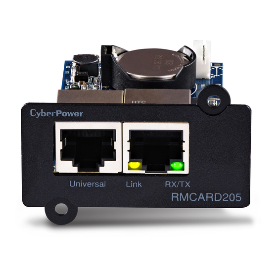
- Page 5 CyberPower Remote Management System Front Panel RMCARD205 1. Universal Port 2. Ethernet Port RMCARD305 3. Tx/Rx Indicator 4. Link Indicator LED Status Indicators Link LED Condition The Remote Management Card is not connected to the Network/ or the Remote Management Card power is off...
-
Page 6: Installation Guide
Installation Guide Step 1. Hardware Installation Note: The CyberPower Remote Management Card is hot-swappable, so you do not need to turn off the UPS to install it. 1. Remove the two retaining screws from the expansion slot and remove the cover. - Page 7 CyberPower Remote Management System RMCARD305 Step 2. Configure the IP address for the CyberPower Remote Management Card Note: These instructions are for Windows OS. For other OS please refer to Appendix 4. Method 1: Using the Power Device Network Utility 1.
- Page 8 CyberPower Remote Management System select “Device Setup” or double click the device you want to configure. 5. You can modify the IP Address, Subnet Mask, and Gateway address for the Device MAC Address listed in the Device Network Settings window, as shown in Figure 2. The factory default IP Address is 192.168.20.177 and the default Subnet Mask is...
- Page 9 CyberPower Remote Management System 8. If the IP address change is successful, you will see a message confirming the IP set up is OK, as shown in Figure 4. Figure 4. Setup IP Address successfully message. 9. In case the change is not successful, for example, if the IP address change is unsuccessful you will see a warning message.
-
Page 10: Web Interface
CyberPower Remote Management System Web Interface Login User Account You will need to enter a User Name and Password to login to the interface, and can select a preferred language after login. There are two user account types. 1. Administrator... - Page 11 CyberPower Remote Management System Item Definition Envir Data Name The name of the environmental sensor. Location The location of the environmental sensor. A list of the five most recent device events. All events are related Recent Device Events to configuration changes.
- Page 12 CyberPower Remote Management System Item Definition Apparent Power The product of the current and voltage of the circuit. The portion of power flow that is temporarily stored in the form of magnetic or electric fields, due to inductive and Reactive Power capacitive network elements, and then returned to source, is known as reactive power.
- Page 13 CyberPower Remote Management System Item Definition Display the current battery voltage equalization status of UPS/EBM battery pack. Equalization Status Active: The battery pack equalization function is active. Inactive: The battery pack equalization function is not active. [UPS->Information] Display the technical specifications of the UPS.
- Page 14 CyberPower Remote Management System [UPS->Configuration] Configure the parameters of the UPS. Item Definition Supplied Power Set the UPS output voltage that is supplied to the connected Voltage equipment. Utility Power Failure Condition When the UPS detects the utility voltage is out of range, the UPS will switch to battery mode to protect the equipment plugged into the UPS.
- Page 15 CyberPower Remote Management System Item Definition Note: The UPS may automatically enter Bypass Mode per these Bypass configured settings. No Bypass: If this option is selected, the UPS will not enter Bypass Mode and will stop supplying output power. Check Volt/Freq: If the utility voltage is in the range of the...
- Page 16 CyberPower Remote Management System Item Definition The UPS will cyclically perform the battery test automatically to ensure the batteries have full functional. Periodical Battery Note: Only Online (OL) series support the Smart Battery Test Management (SBM) feature. SBM carries out battery tests, even if Periodical Battery Test setting is disabled.
- Page 17 CyberPower Remote Management System Item Definition If this option is enabled, the UPS will enter sleep mode after all ® PowerPanel Remote shundown +2 minutes. Enter Sleep Mode Note: For PowerPanel® Business Edition Clients, if this option is After All Remote...
- Page 18 CyberPower Remote Management System [UPS->Master Switch] Switch the output power of the UPS to be on or off. Item Definition Reboot UPS Turns the UPS off and back on Turn UPS Off Turns the UPS off. This command is available in Utility Power Failure Mode. It puts UPS Sleep the UPS in sleep mode until power is restored.
- Page 19 Last Test Result Repeat the battery test and replace the batteries if the test fails again. Contact CyberPower for assistance if the battery test fails after the batteries have been replaced. Last Test Date The date of the most recent battery test.
- Page 20 CyberPower Remote Management System Item Definition The results of the last Runtime Estimation. Passed: The runtime estimation was completed and the Last Estimation Result batteries are good. Canceled: The runtime estimation was interrupted. Last Estimation Date The date the last runtime estimation was performed.
- Page 21 [UPS->EnergyWise] The EnergyWise initiative focuses on reducing the energy consumption of all devices connected to a Cisco network. Through this compatibility, the CyberPower Remote Management Card is recognized to work with other EnergyWise-enabled entities and can be easily monitored and controlled to achieve the best energy performance under the EnergyWise operation framework.
- Page 22 CyberPower Remote Management System ® ® [UPS->PowerPanel List] Display the Information of the connected PowerPanel ® Business. The connection is established by PowerPanel Business. The listed will be removed if disconnected for 1 hour. Item Definition Configuration Remote The max time that all the connected Remote require to Shutdown Time (MST) shutdown.
- Page 23 CyberPower Remote Management System [Envir] Following items can be displayed/configured through the Envir page. Note that Envir Tab only appears when an ENVIROSENSOR is connected to the RMCARD. [Envir->Status] Display the basic information of the environmental sensor and contact closure inputs.
- Page 24 CyberPower Remote Management System Item Definition Rate of Change The rate used to define an abnormal change in humidity. Enter the name of each input dry contact relay and use the Contact dropdown menu to define the normal status of each one.
- Page 25 CyberPower Remote Management System [Logs->Graphing] This page is used to display the data of the Status Record. The graphing function makes the status records easier to view. Item Definition The period used to draw the graph. Longer periods will require more Graph Period time to be displayed.
- Page 26 CyberPower Remote Management System Item Definition CO2 Emissions The ratio of CO2 emissions to energy. Save Energy Save the existing event logs as a text file. Records Note: Event Logs and Status Records use a First In First Out memory. Oldest data will be rewritten once memory is full.
- Page 27 CyberPower Remote Management System [System->General->Daylight Saving Time] Adjust the clock daylight saving time. Item Definition DST Configuration Disable Disable DST. Set traditional US DST settings Tradition US Start: 2:00, second Sunday in March. End: 2:00, first Sunday in November. Manual DST Manual DST date time rules.
- Page 28 CyberPower Remote Management System [System->Security->Local Account] This page is used to configure the login account. Information Description Administrator has full access to read/write configuration Administrator settings. Viewer Viewer has restricted access to read only. Change Administrator account: 1. Enter User Name 2.
- Page 29 CyberPower Remote Management System [System->Security->LDAP Configuration] After setting the proper LDAP server, the Remote Management Card can use user name and password that set on the LDAP server to login. Item Definition LDAP Server LDAP Server The IP address/domain of LDAP server.
- Page 30 CyberPower Remote Management System [System->Security->Session Control] Set for timeout setting for open sessions to automatically log off. Item Definition The period (in minutes) that the system waits before automatically Timeout logging off. [System->Network Service->TCP/IPv4] Display the current TCP/IPv4 settings. Set DHCP and DNS server settings.
- Page 31 CyberPower Remote Management System [System->Network Service->SNMPv1 Service] Allow users to use a NMS and configure the appropriate SNMPv1 settings. Item Definition SNMPv1 Service Allow Access Set the SNMP service to either Enable or Disable. SNMPv1 Access Control The name used to access this community from a Network Community Management System (NMS).
- Page 32 CyberPower Remote Management System Item Definition NMS access can be restricted by entering a specific IP address or an IP network subnet mask. The following subnet mask rules apply: • 192.168.20.255: Access only by an NMS on the 192.168.20 IP Address segment.
- Page 33 CyberPower Remote Management System [System->Network Service->Console Service] Select Enable to allow access to the Telnet or SSH Service and configures the TCP/IP port that Telnet or SSH uses to communicate. Item Definition Access Enable the access to Telnet or SSH version 2, which encrypts Allow Access transmission of user names, passwords and data.
- Page 34 CyberPower Remote Management System [System->Notifications->SMTP Server] After setting the proper SMTP server, event notification email can be sent to recipients when specific events occur. Item Definition The service provider of e-mail account. There are two options: Service Provider General and Gmail.
- Page 35 CyberPower Remote Management System [System->Notifications->SMS Service] Short Message Service (SMS) is a communication service used by mobile communication systems. Using standardized communication protocols will allow the interchange of short text messages between mobile devices. The system provides 4 methods for users to choose how they want to send the messages.
- Page 36 CyberPower Remote Management System Item Definition This specification from the SMS provider is required before using the HTTP POST method to deliver messages via SMS providers. Select the Using HTTP POST option in the SMS Method field. Insert E_PHONE_NUMBER as recipient's mobile...
- Page 37 Click the "Save" button to save all diagnostic information to a file. The saved information includes Event Logs, Status Diagnostic Information Records and other RMCARD/UPS/ATS information. Its suggested to have this information saved when contacting CyberPower Technical Support for assistance.
-
Page 38: Command Line Interface
CyberPower Remote Management System Command Line Interface How to log on Users can log on to the command line interface through either console network access (Telnet or SSH) or local access (Serial port). 1. Network access to the command line interface When user logs in with the admin username and admin password through Telnet or SSH, there are two types of interfaces available. - Page 39 CyberPower Remote Management System 2. Local access to the command line interface To log on via serial connection, the PC/server must be connected directly to the Universal port of the RMCARD using the included RJ45/DB9 Serial Port Connection Cable, and perform the following steps.
- Page 40 Display UPS input information output show Display UPS output information Example 1: To view UPS information CyberPower > ups info show UPS information Model: OL1000XL Voltage Rating: 100V Working Frequency: 40~70 Hz Power Rating: 1000 VA Current Rating: 10 Amp...
- Page 41 Example 1: To reboot UPS turn off delay 10sec and reboot duration 20sec. CyberPower > upsctrl reboot 10/20 upscfg Description: Show and configure UPS supply power, UPS sensitivity, UPS high voltage threshold, UPS low voltage threshold, UPS bypass condition, UPS bypass high threshold, UPS bypass low threshold, UPS recharge delay, UPS recharge capacity, UPS working mode, and UPS return delay.
- Page 42 CyberPower Remote Management System Option Argument Description No Bypass-If this option is selected, the UPS will not enter Bypass mode and will stop supplying output power. Check Volt/Freq-If the utility voltage is in the range of the High/Low Bypass Voltage and the...
- Page 43 To view the available value voltage this UPS output power can be set. CyberPower > upscfg supply? Example 2: To define bypass condition as check utility voltage only CyberPower > upscfg bypasscond voltonly Example 3: To define UPS recharge delay as 2 minutes CyberPower > upscfg rechargedelay 120...
- Page 44 To start battery runtime calibration CyberPower > upsbatt cal start Example 3: To set the battery replacement date as May 29, 2018. CyberPower > upsbatt rdyyyy 2018 rdmm 5 rddd 29 atsoltsta Description: Show information of ATS outlet status. Option...
- Page 45 To name outlet #1 as test_1, set turn on delay as 3 seconds, set turn off delay as 4 seconds and set reboot duration as 5 seconds with a single command CyberPower > atsoltcfg set 1 test_1 3 4 5...
- Page 46 Control ATS Outlet | td_on | td_off | td_reboot> Example 1: To turn on outlet #1 immediately CyberPower > atsoltctrl index 1 act on Example 2: To turn on outlet #2 with turn on delay CyberPower > atsoltctrl index 2 act td_on atssrccfg Description: Show and configure ATS prefer source.
- Page 47 To define timezone offset as +08:00 CyberPower > date timezone +0800 Example 2: To define the date as March 21, 2015 CyberPower > date yyyy 2015 mm 3 dd 21 Example 3: To define the time as 13:45:12 CyberPower > date time 13:45:12 Description: Show and configure NTP server IP, NTP update interval time.
- Page 48 Name: RMCARD205 (305) Location: Server Room Contact: Admainistrator Model: RMCARD205 (305) Hardware Version: 1.1 Firmware Version: 1.0.3 Firmware Update Date: 03/08/2015 Serial Number: TALGY2001975 MAC Address: 00-0C-15-00-B9-42 Example 2: To reset RMCARD to default parameter. CyberPower > sys reset all...
- Page 49 Jan | Feb | Mar | Apr | May | Jun | Jul | Aug | Sep | Oct | Nov | Dec Example 1: Manual set Daylight Saving Time CyberPower > dst type manual Start time (0~23): 2 Start week of month: second Start day of week: Sun...
- Page 50 The period (in minutes) that the system waits timeout 1~10 before auto logging off. The range of argument is from 1 to 10 (in minutes). Example 1: To change authentication type to Radius, Local Account CyberPower > login type radiuslocal...
- Page 51 Set user name of admin/device passwd <user password> Set user password of admin/device Example 1: To define primary admin manager IP as 192.168.26.0/24 CyberPower > admin primip 192.168.26.0/24 Input admin password : cyber Pass radius Description: Show and configure information of radius server. Option...
- Page 52 Enter the following command to add Radius server information configuration with a single command: radius add <Server IP> <Share Secret> <Server Port> For example: CyberPower > radius add 192.168.203.55 testsecret 150 Note: This single command could not be executed successfully if there are two Radius servers to be set already. ldap Description: Show and configure information of LDAP server.
- Page 53 CyberPower Remote Management System Option Argument Description priattr < LDAP server login Set the Login Attribute of primary/secondary secattr attribute> LDAP user entry. pridel Delete primary/secondary LDAP server. secdel Example 1: To add LDAP Server CyberPower > ldap add Input LDAP Server Type [openldap | ad]: ad Input IP address: 192.168.26.33...
- Page 54 <manual IPv6 IP> Set manual IPv6 ip. Example 1: To define IPv6 manual IP address then show the information of IPv6 CyberPower > tcpip6 manual enable ip 2001:cdba:0:0:0:0:3257:9652 show Access: Enable Router Control: Enable Manual: Enable Manual IPv6 Address: [2001:cdba::3257:9652]...
- Page 55 Enter the following command to perform all parameters configuration with a single command: snmpv1 set <1 | 2 | 3 | 4> <Community> <IP Address> <readonly | readwrite | forbidden> For example: CyberPower > snmpv1 set 3 CyberPower 192.168.203.91 readonly...
- Page 56 IP Address: 192.169.30.58 Auth Protocol: MD5 Priv Protocol: aes Example 2: To change the user name of second SNMPv3 user to CyberPower CyberPower > snmpv3 index 2 name CyberPower Example 3: To enable the third SNMPv3 user CyberPower > snmpv3 index 3 status enable Example 4: To change the IP address of forth SNMPv3 user to 192.168.203.66...
- Page 57 <1 | 2 | 3 | 4> <User Name> <IP Address> <md5 | sha | none> <Auth Key> <aes | des | none> <Priv Key> For example:. CyberPower > snmpv3 set 1 CyberPower 192.168.203.90 sha test_authkey_123456 des test_privkey_123456...
- Page 58 Example 5: To change the fifth trap receiver CyberPower > trap index 5 status enable. Example 6: To change the community name of second trap receiver to CyberPower with the condition that the SNMP version of trap receiver must be SNMPv1.
- Page 59 For SNMPv1: trap add <Trap Name> <Trap Receiver IP> v1 <Community> For example: CyberPower > trap add CyberPower 192.168.203.16 v1 test For SNMPv3: trap add <Trap Name> <Trap Receiver IP> v3 <1 | 2 | 3 | 4> For example: CyberPower >...
- Page 60 <ssh port> communicate. Example 1: To enable Telnet as console type CyberPower > console telnet enable Example 2: To disable SSH as console type CyberPower > console ssh disable Note: The telnet and the ssh modes are options for switching between each other. For example, the telnet will be automatically disabled once ssh is enabled as console type and vice versa.
- Page 61 Enable or disable FTP server port <ftp port> The TCP/IP port of the FTP server (21 by default). Example 1: To enable FTP service CyberPower > ftp access enable eventlog Description: View and clear the eventlog of RMCARD and UPS. Option Argument Description...
- Page 62 CyberPower Remote Management System syslog Description: Show and configure information of SYSLOG server. Option Argument Description show Display all syslog information for RMCARD Display syslog server information for 1 to 4 show servers. Add syslog server then input syslog server IP /Port appear later on.
- Page 63 Enter the following command to perform all parameters configuration with a single command: syslog add <Server IP address> <Server Port> For example: CyberPower > syslog add 192.168.203.65 180 Note: This single command could not be executed successfully if there are four Syslog servers to be set already. menumode Description: Switch mode as Menu Mode.
-
Page 64: Reset To Factory Default Setting / Recover From A Lost Password
CyberPower Remote Management System Reset to Factory Default Setting / Recover from a Lost Password To reset the CyberPower Remote Management Card to its factory default setting (including web log-in user name and password), please following these steps: RMCARD205 RMCARD305 1. -
Page 65: Rmcard Firmware Upgrade
- A. cpsrm2scfw_XXX.bin - B. cpsrm2scdata_XXX.bin Note: To ensure keeping RMCARD firmware up to date, please visit CyberPower website every 3 months to see if there is any updated firmware version available. Note: Please do not turn the UPS off when processing the Firmware upgrade. - Page 66 CyberPower Remote Management System Method 2: Using Upgrade and Configuration Utility (Bulk firmware upgrade tool) 1. Install the CyberPower Upgrade and Configuration Utility tool available for download at www.CyberPower.com. 2. After installation completes, run the “Upgrade and Configuration Utility”. 3. The main window of the Upgrade and Configuration Utility tool program is shown in Figure 6.
- Page 67 CyberPower Remote Management System Figure 7. The File Locations of Firmware & Data window. 7. Click “Yes” to start firmware upgrade on selected devices, as shown in Figure 8. Figure 8. Confirm Upgrade Firmware message window 8. If the firmware upgrade is implemented, you will see the Result in the main window, as shown in Figure 9.
- Page 68 CyberPower Remote Management System Method 3: Using Secure Copy (SCP) command Use the following steps to update firmware via SCP. Note: Only firmware version 1.1.2 and above supports the functionality to update firmware via SCP. For Windows Users: 1. Download any PuTTY Secure Copy client (PSCP) utility.
- Page 69 CyberPower Remote Management System For Linux, MacOS and Unix Users: 1. Install the related distribution of an SSH or SCP client, for example Openssh client. 2. Open the Terminal and change the path to where the firmware files are saved.
- Page 70 CyberPower Remote Management System Figure 10. Firmware Update in the main window. 3. If the firmware upgrade is implemented, you will see the Result in the main window, as shown in Figure 11. Figure 11. Firmware upgrade success in the main window.
-
Page 71: Save And Restore Configuration Settings
CyberPower Remote Management System Save and Restore Configuration Settings Method 1: Using Web Interface You can easily save and restore the device configuration to your local PC on [System->About] Figure 12. Save/Restore Configuration in the main window. You can easily save and restore the device configuration to your local PC on the [System->About], as shown in Figure 12. - Page 72 CyberPower Remote Management System For Windows Users: 1. Download any PuTTY Secure Copy client (PSCP) utility. 2. Save the configuration file and the PSCP Utility in the same folder. 3. Open the Command Line Interface and change the path to where the configuration file and the PSCP Utility are saved.
-
Page 73: Upload Ssh Host Key Via Secure Copy (Scp)
Upload SSH Host key via Secure Copy (SCP) A SSH HOST Key can be uploaded to RMCARD205 with Secure Copy commands. Please make sure the uploaded filename contains the start string of “ssh_hostkey_” . Some examples of acceptable file name are as following: sample1.pem... -
Page 74: Troubleshooting
►Ensure the network connection is good. method 2 2. Ensure the PC being used is on the same local network subnet as the CyberPower device you are trying to communicate with. 3. Ensure the Jumper on the Reset Pin is correctly installed. -
Page 75: Conformance Approvals
CyberPower Remote Management System Conformance Approvals FCC Warning This equipment has been tested and found to comply with the limits for a Class A Digital Device, pursuant to Part 15 of the FCC Rules. These limits are designed to provide reasonable protection against harmful interference in residential installation. -
Page 76: Appendix 1: Ip Address Identification For Cyberpower Remote Management Card
The same address cannot be used twice. In order to assign an IP address to the CyberPower Remote Management Card, you must determine the range of the available IP addresses, and then choose an unused IP address to assign to the Remote Management Card. - Page 77 Address, run “Ping 192.168.20.240” at the DOS Mode prompt when the IP Address you would like to set is 192.168.20.240. If the response is presented as below, the IP address is most likely not used and may be available for the CyberPower Remote Management Card. Pinging 192.168.20.240 with 32 bytes of data: Request timed out.
-
Page 78: Appendix 2: How To Configure A Rmcard User Account In Authentication Servers
CyberPower Remote Management System Appendix 2: How to Configure a RMCARD User Account in Authentication Servers RADIUS 1. Add a new attribute to RADIUS Dictionary as the Cyber vendor: 3808 – Vendor 2. Add two new specific attributes to RADIUS server interface under the vendor:... -
Page 79: Appendix 3: Ups Firmware Upgrade
1. Turn off the UPS. 2. Extract the update file to “C:\” 3. Open a command prompt window 4. Login to the CyberPower Remote Management Card with FTP command, in the command prompt type: (1) ftp (2) ftp > open (3) To [current IP address of RMCARD] [port];... -
Page 80: Appendix 4: Software Support
Business Remote is used to perform a graceful operating system shutdown ® when protected by a UPS/ATS PDU with a remote management card installed. PowerPanel Business software is available on CyberPower Systems official website. Please visit www.CyberPower.com and go to the software section for free download. ®... - Page 81 CyberPower Remote Management System Obtain IP Address for Linux Operating System The instructions in ‘Configure the IP address for the CyberPower Remote Management ® Card’ section are for Windows OS. For Linux Operating System, please use PowerPanel Business Remote software to scan and obtain the IP address. To do this, go to ®...
-
Page 82: Appendix 5: Rmcard Adapter Guide
RMCARD205 front seated in place. panel. Note: The RMCARD Adapter Kit is not included with the RMCARD205. Please contact CyberPower for ordering information or Technical Support. Note: RMCARD205 is designed for the 43x18mm (1.69x0.71inch) SNMP card expansion port of CyberPower PR, OR, and 1-3kVA OL series UPS, and ATS PDU. - Page 83 Cyber Power Systems, Inc. www.cyberpower.com For USA and Canada: 4241 12th Ave East, Suite 400 Shakopee, MN 55379 Toll-free: (877) 297-6937 For all other regions: Please visit our website for local contact information. K01-E000001-14...
Need help?
Do you have a question about the RMCARD205 and is the answer not in the manual?
Questions and answers