CyberPower RMCARD205 User Manual
Remote management card
Hide thumbs
Also See for RMCARD205:
- User manual (83 pages) ,
- Quick start manual (18 pages) ,
- Quick start manuals (2 pages)
Table of Contents

Related Manuals for CyberPower RMCARD205


Summary of Contents for CyberPower RMCARD205
- Page 1 Remote Management Card RMCARD205 / RMCARD305 User’s Manual Rev. 03 The Remote Management Card allows a UPS system and environmental sensor to be managed, monitored, and configured. © 2016, CyberPower Systems, Inc. All rights reserved. K01-E000001-00...
-
Page 2: Table Of Contents
TABLE OF CONTENTS Introduction ....................1 Installation Guide ..................3 Web Interface .................... 8 Command Line Interface ................. 28 Reset to Factory Default Setting / Recover from a Lost Password ..44 Firmware Upgrade ................... 45 Save and Restore Configuration Settings ..........48 Troubleshooting .................. -
Page 3: Introduction
Overview The CyberPower Remote Management Card allows for remote monitoring and management of a UPS attached to a network. After installing the hardware and configuring an IP address, the user can access, monitor, and control the UPS from anywhere in the world! Simply use a web browser or SSH client to access your UPS. - Page 4 Inspect the Remote Management Card upon receipt. The package should contain the following: CyberPower Remote Management Card RJ45/DB9 Serial Port Connection Cable Quick Start Guide Spare Jumper RMCARD Adapter Guide (RMCARD305 only) RMCARD205 Front Panel (RMCARD305 only)
-
Page 5: Installation Guide
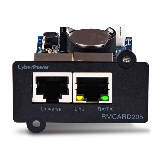
2. Install the CyberPower Remote Management Card into the expansion slot. 3. Insert and tighten the retaining screws. 4. Connect an Ethernet cable to the Ethernet port of the CyberPower Remote Management Card. 5. (Optional) To connect the environmental sensor, use a RJ45 Ethernet cable. Connect one end to the Universal port on the RMCARD and the other end into the sensor. - Page 6 CyberPower Remote Management System Definitions for LED Indicators Link LED color Condition The Remote Management Card is not connected to the Network/ or the Remote Management Card power is off On (Yellow) The Remote Management Card is connected to the Network...
- Page 7 3. The main dialog of the Power Device Network Utility program is shown in Figure 1. The configuration tool will display all CyberPower Remote Management devices present on the same network subnet. The "Refresh" button is used to search the local network subnet again.
- Page 8 CyberPower Remote Management System 5. You can modify the IP Address, Subnet Mask, and Gateway address for the Device MAC Address listed in the Device Network Settings window, as shown in Figure 2. The factory default IP Address is 192.168.20.177 and the default Subnet Mask is 255.255.255.0.
- Page 9 CyberPower Remote Management System 8. If the IP address change is successful, you will see a message confirming the IP set up is OK, as shown in Figure 4. Figure 4. Setup IP Address successfully message. 9. In case the change is not successful, for example, if the IP address change is unsuccessful you will see a warning message.
-
Page 10: Web Interface
CyberPower Remote Management System eb Interface Login User Account You will need to enter a User Name and Password to login to the interface, and can select a preferred language after login. There are two user account types. 1. Administrator (Both combinations of default user name and password can work.) - Page 11 CyberPower Remote Management System Envir Data Name The name of the environmental sensor. Location The location of the environmental sensor. Recent Device Events A list of device events that recently occurred. [UPS] The following items can be displayed/configured through the UPS page; however, different UPS models may have different items displayed/configured.
- Page 12 CyberPower Remote Management System [UPS->Information] Display the technical specifications of the UPS. Information Description Model The model name of the UPS. Serial Number The serial number of the UPS. Voltage Rating The nominal output voltage rating (Volts) of the UPS.
- Page 13 CyberPower Remote Management System High/Low Input (or When the utility power voltage or output voltage (depending on UPS Output) Voltage model) is higher/lower than the threshold, the UPS will supply battery Threshold power to the connected equipment. Sets the acceptable range of the input frequency. The UPS will supply Frequency Tolerance battery power to the connected equipment if it is out of tolerance.
- Page 14 CyberPower Remote Management System When the UPS is in Battery Mode and utility power is restored, the UPS will wait for the specific delay time to change Battery Mode to Line Mode. Line Stable Delay When the UPS battery is lower than the Low Battery Threshold and utility power is restored, the UPS will return to Line Mode immediately.
- Page 15 CyberPower Remote Management System Non-Critical Outlet Bank When supplying battery power, the UPS will power off this NCL outlet Turn Off Threshold bank if the remaining battery capacity is lower than this threshold. When supplying battery power, the UPS will power off this NCL outlet Turn off Delay bank after this delay time is met.
- Page 16 Follow the steps below if the battery test fails: Repeat the battery test and replace the batteries if the test fails again. Contact CyberPower for assistance if the battery test fails after the batteries have been replaced. Note: “N/A” means the UPS model does not have the battery test function.
- Page 17 CyberPower Remote Management System [UPS->Schedule]: Sets the UPS to automatically shutdown and restart at scheduled times (Once/Daily/Weekly). The Schedule page manages scheduled shutdowns and lists all configured schedules. Each schedule row displays the details of when the schedule will take effect.
- Page 18 CyberPower Remote Management System [UPS->EnergyWise] The EnergyWise initiative focuses on reducing the energy consumption of all devices connected to a Cisco network. Through this compatibility, the CyberPower Remote Management Card is recognized to work with other EnergyWise-enabled entities and can be easily monitored and controlled to achieve the best energy performance under the EnergyWise operation framework.
- Page 19 CyberPower Remote Management System [Envir] Following items can be displayed/configured through the Envir page. [Envir->Status] Display the basic information of the environmental sensor and contact closure inputs. Item Definition Information Name The name of the environmental sensor. Location The location of the environmental sensor.
- Page 20 CyberPower Remote Management System [Logs->Event Logs] Display the list of events and a brief description of each event along with the date and time stamp. Note: 1. The recordable events are listed under “System->Notifications->Event Action.” 2. The recorded time is using the 24-hour clock format.
- Page 21 CyberPower Remote Management System [Logs->Maintenance] This page is used to select “Event Logs” and “Status Records” settings. The application provides information on how many events are recorded before it is full. Item Definition Event Logs Clear All Logs Clear the existing event logs.
- Page 22 CyberPower Remote Management System [System->General->Daylight Saving Time] Adjust the clock daylight saving time. Item Definition DST Configuration Disable Disable DST. Set traditional US DST settings Tradition US DST Start: 2:00, second Sunday in March. End: 2:00, first Sunday in November.
- Page 23 CyberPower Remote Management System 5. Enter Confirm Password 6. Click “Apply” Change Viewer account: 1. Select “Allow Access” to enable the Viewer account 2. Enter the User Name 3. Set the Manager IP (optional) 4. Enter New Password 5. Enter Confirm Password 6.
- Page 24 CyberPower Remote Management System [System->Security->Session Control] Set for timeout setting for open sessions to automatically log off. Item Definition The period (in minutes) that the system waits before automatically Timeout logging off. [System->Network Service->TCP/IPv4] Display the current TCP/IPv4 settings. Set DHCP and DNS server settings.
- Page 25 CyberPower Remote Management System • 192.255.255.255: Access only by an NMS on the 192 segment. • 0.0.0.0 (the default setting) or 255.255.255.255: Access by any NMS on any segment. The allowable action for the NMS through the community and IP address.
- Page 26 CyberPower Remote Management System ‧ 3DES (168 bits) ‧ DES (168 bits) ‧ RC4 SHA (128 bits) ‧ RC4 MD5 (128 bits) Http Settings The TCP/IP port of the Hypertext Transfer Protocol (HTTP) (80 by Http Port default) Https Settings...
- Page 27 CyberPower Remote Management System [System->Notifications->Event Action] Configure notification settings for every Device Event. Events are categorized for ease of management. • Log: Record the event in the “Event Logs”. • E-mail: Send an email to a specific user (An available SMTP server is necessary).
- Page 28 CyberPower Remote Management System This specification from the SMS provider is required before using the HTTP GET method. Select the Using HTTP GET option in the SMS Method field. Insert the E_PHONE_NUMBER as recipient's mobile Service provider accepts phone number and the E_PHONE_MESSAGE as event message,...
- Page 29 CyberPower Remote Management System [System->About] Display system information for the Remote Management Card. Item Definition Model Name Model name of the Remote Management Card. Hardware Version The hardware version of the Remote Management Card. The version number of the current firmware installed on Remote Firmware Version Management Card.
-
Page 30: Command Line Interface
CyberPower Remote Management System ommand Line Interface How to log on User can log on command line interface through either a console network access (Telnet or SSH) or a local access (Serial Connection). 1. Network access to the command line interface When user logs in with the admin username and admin password through Telnet or SSH, there are two types of interfaces available. - Page 31 CyberPower Remote Management System 2. Local access to the command line interface To log on via serial connection, the PC/server must be connected directly to the Universal port of the RMCARD using the included RJ45/DB9 Serial Port Connection Cable, and perform the following steps.
- Page 32 Display UPS input information output show Display UPS output information Example 1: To view UPS information CyberPower > ups info show UPS information Model: OL1000XL Voltage Rating: 100V Working Frequency: 40~70 Hz Power Rating: 1000 VA Current Rating: 10 Amp...
- Page 33 CyberPower Remote Management System upscfg Description: Show and configure UPS supply power, UPS sensitivity, UPS high voltage threshold, UPS low voltage threshold, UPS bypass condition, UPS bypass high threshold, UPS bypass low threshold, UPS recharge delay, UPS recharge capacity, UPS working mode, and UPS return delay.
- Page 34 To view the available value voltage this UPS output power can be set. CyberPower > upscfg supply? Example 2: To define bypass condition as check utility voltage only CyberPower > upscfg bypasscond voltonly Example 3: To define UPS recharge delay as 2 minutes CyberPower > upscfg rechargedelay 120...
- Page 35 To define timezone offset as +08:00 CyberPower > date timezone +0800 Example 2: To define the date as March 21, 2015 CyberPower > date yyyy 2015 mm 3 dd 21 Example 3: To define the time as 13:45:12 CyberPower > date time 13:45:12...
- Page 36 1-8760-Set the frequency to update the date and time from NTP server. Example 1: To enable NTP server define date and time of RMCARD CyberPower > ntp access enable Example 2: To setup primary NTP server IP as “192.168.26.22” CyberPower > ntp priip 192.168.26.22...
- Page 37 Hardware Version: 1.1 Firmware Version: 1.0.3 Firmware Update Date: 03/08/2015 MAC Address: 00-0C-15-00-B9-42 Example 2: To reset RMCARD to default parameter. CyberPower > sys reset all Description: Show and configure type of Daylight Saving Time. Option Argument Description show Display all DST information for RMCARD disable-Disable DST.
- Page 38 The period (in minutes) that the system waits before auto timeout 1~10 logging off. The range of argument is from 1 to 10 (in minutes). Example 1: To change authentication type to Radius, Local Account CyberPower > login type radiuslocal...
- Page 39 Set user name of admin/device passwd <user password> Set user password of admin/device Example 1: To define primary admin manager IP as 192.168.26.0/24 CyberPower > admin pmip 192.168.26.0/24 Input admin password : cyber Pass radius Description: Show and configure information of radius server. Option...
- Page 40 CyberPower Remote Management System Example 2: To view radius server information CyberPower > radius show Primary Radius Server Server IP: 192.168.26.33 Server Secret: testsecret Server Port: 1812 ldap Description: Show and configure information of LDAP server. Option Argument Description show...
- Page 41 <system dns> Set DNS of system Example 1: To disable DHCP and define IP address to 192.168.26.33 CyberPower > tcpip dhcp disable ip 192.168.26.33 tcpip6 Description: Show and configure status of IPv6 router control, IPv6 manual IP. Option Argument...
- Page 42 CyberPower Remote Management System Example 1: To define IPv6 manual IP address then show the information of IPv6 CyberPower > tcpip6 manualip 2001:cdba:0:0:0:0:3257:9652 show Access: Enable Router Control: Enable Manual: Enable Manual IPv6 Address: [2001:cdba::3257:9652] snmpv1 Description: Show and configure status of SNMPv1.
- Page 43 <ssh port> communicate. Example 1: To set SSH server port to 5000 and enable the access to SSH CyberPower > console sshport 5000 access ssh Description: Show and configure FTP access type and TCP/IP port of FTP. Option Argument Description...
- Page 44 CyberPower Remote Management System Example 2: To clear all event logs. CyberPower > eventlog clear Do you want to clear all eventlog [yes / no]: yes syslog Description: Show and configure information of SYSLOG server. Option Argument Description show Display all syslog information for RMCARD Add syslog server then input syslog server IP /Port appear later on.
- Page 45 CyberPower Remote Management System Example 2: To view information of syslog CyberPower > syslog show Syslog: Enable Facility Code: user Server1 IP: 192.168.26.33 Port: 514 menumode Description: Switch mode as Menu Mode. exit Description: Close the connection to the command line interface.
-
Page 46: Reset To Factory Default Setting / Recover From A Lost Password
CyberPower Remote Management System eset to Factory Default Setting / Recover from a Lost Password To reset the CyberPower Remote Management Card to its factory default setting (including web log-in user name and password), please following these steps: RMCARD205 RMCARD305 1. -
Page 47: Firmware Upgrade
Use the following steps to upgrade the firmware: 1. Download the latest firmware 2. Extract the downloaded files to “C:\” 3. Open a command prompt window 4. Login to the CyberPower Remote Management Card with FTP command, in the command prompt type: (1) ftp (2) ftp> open (3) To [current IP address of RMCARD] [port];... - Page 48 CyberPower Remote Management System Method 2: Using Upgrade and Configuration Utility tool (Bulk firmware upgrade tool) 1. Install the CyberPower Upgrade and Configuration Utility tool available for download on the Network Power Management product web page at www.CyberPower.com. 2. After installation completes, run the “Upgrade and Configuration Utility”.
- Page 49 CyberPower Remote Management System 6. Select the Firmware and Data files and click “OK” to implement firmware upgrade, as shown in Figure 7. Figure 7. The File Locations of Firmware & Data window. 7. If the firmware upgrade is implemented, you will see the Result in the main dialog, as shown in Figure 8.
-
Page 50: Save And Restore Configuration Settings
CyberPower Remote Management System ave and Restore Configuration Settings Figure 9. Save/Restore Configuration in the main window. You can easily save and restore the device configuration to your local PC on the [System->About]. To save the configuration file, click “Save” to save the configuration to your local PC. The text file will have a default format of YYYY_MM_DD_HHMM.txt. -
Page 51: Troubleshooting
2 2. Ensure the PC being used is on the same network subnet as the CyberPower device you are trying to communicate with. 3. Ensure the Jumper on the Reset Pin is correctly installed. 1. Use method 1 and/or method 2 to get/set a correct IP address for the Remote Management Card. -
Page 52: Conformance Approvals
CyberPower Remote Management System onformance Approvals FCC Warning This equipment has been tested and found to comply with the limits for a Class A Digital Device, pursuant to Part 15 of the FCC Rules. These limits are designed to provide reasonable protection against harmful interference in residential installation. -
Page 53: Appendix 1
All devices on a computer network need to have an IP address. Each device’s IP address is unique. The same address cannot be used twice. In order to assign an IP address to the CyberPower Remote Management Card, you must determine the range of the available IP addresses, and then choose an unused IP address to assign to the Remote Management Card. - Page 54 CyberPower Remote Management System 2. Select an IP Address for the CyberPower Remote Management Card Verify the IP Addresses for the computer and the Remote Management Card belong to the same subnet. Refer to the above network information, the possible IP Address for the Remote Management Card could be 192.168.20.* (* hereafter represents any number between 1 and 255).
-
Page 55: Appendix 2
CyberPower Remote Management System ppendix 2 ow to Configure a RMCARD User Account in Authentication Servers RADIUS Add two new attributes to RADIUS server interface: 1. Cyber-Service-Type (integer variable) Cyber-Service-Type can accept three integer parameter values: 1 – Administrator 2 – Viewer 3 –... -
Page 56: Appendix 3
3 oftware Support ® PowerPanel Business Edition Client can support a CyberPower Systems device with a remote ® management card via the network. PowerPanel Business Edition software is available on CyberPower Systems official website. Please visit www.CyberPower.com and go to the software section for free download. - Page 57 CyberPower Remote Management System Obtain IP Address for Linux Operating System The instructions in ‘Configure the IP address for the CyberPower Remote Management Card’ ® section are for Windows OS. For Linux Operating System, please use PowerPanel Business Edition Client software to scan and obtain the IP address. To do this, go to [Power->Configuration] ®...
-
Page 58: Appendix 4
CyberPower for ordering information or Technical Support. Note: RMCARD205 is designed for the 43x18mm (1.69x0.71inch) SNMP card expansion port on CyberPower PR and OR series UPS and ATS PDU. RMCARD305 is designed for the 57x23mm (2.24x0.91inch) SNMP card expansion port on CyberPower OL series UPS. - Page 59 CyberPower Systems, Inc. www.cyberpower.com For USA and Canada: 4241 12th Ave East, Suite 400 Shakopee, MN 55379 Toll-free: (877) 297-6937 For all other regions: Please visit our website for local contact information. K01-E000001-00...
Need help?
Do you have a question about the RMCARD205 and is the answer not in the manual?
Questions and answers