
Related Manuals for COBHAM GR-VPX-GR740-BOARD


Summary of Contents for COBHAM GR-VPX-GR740-BOARD
- Page 1 GR-VPX-GR740-BOARD Development Board 2020 User's Manual The most important thing we build is trust GR-VPX-GR740-BOARD Development Board User's Manual GR-VPX-GR740-BOARD-UM, 2020, Version 1.4 www.cobham.com/gaisler...
- Page 2 GR-VPX-GR740-BOARD Intentionally Blank GR-VPX-GR740-BOARD-UM, Nov 2020, Version 1.4 www.cobham.com/gaisler...
-
Page 3: Table Of Contents
Setting Up and Using the Board...................33 Switches and Bootstrap Signals.................33 5.1.1 SP3T Switch description and configuration properties........34 5.1.2 GR740 Bootstrap Signals..................35 5.1.3 Other configurable switches default settings.............37 Jumper configurations..................37 5.2.1 Default Setting of Jumpers – GR-VPX-GR740..........38 Interfaces and Configuration..................39 GR-VPX-GR740-BOARD-UM, Nov 2020, Version 1.4 www.cobham.com/gaisler... - Page 4 GR-VPX-GR740-BOARD List of Connectors – GR-VPX-GR740..............40 List of Connectors – GR-VPX-SPW-MEZZ.............40 List of Oscillators, Switches and LED's - GR-VPX-GR740......47 Change Record.......................52 GR-VPX-GR740-BOARD-UM, Nov 2020, Version 1.4 www.cobham.com/gaisler...
- Page 5 Table 9: List of Connectors – GR-VPX-GR740.................40 Table 10: List of Connectors – GR-VPX-SPW-MEZZ..............40 Table 11: J1 POWER – External Power Connector................41 Table 12: J2 Dual MIL-STD-1553 interface connections..............41 Table 13: J3 RJ45-ETHERNET Connector..................41 Table 14: J4 PPS Input........................41 GR-VPX-GR740-BOARD-UM, Nov 2020, Version 1.4 www.cobham.com/gaisler...
- Page 6 Table 20: J10 SPW-HDR interface connections.................46 Table 21: J11 FPGA– JTAG Connector.....................46 Table 22: List and definition of Oscillators and Crystals..............47 Table 23: List and definition of PCB mounted LED's................47 Table 24: List and definition of Switches...................48 GR-VPX-GR740-BOARD-UM, Nov 2020, Version 1.4 www.cobham.com/gaisler...
-
Page 7: Introduction
Scope of the Document This document provides a User's Manual and Interface document for the “GR-VPX- GR740-BOARD” Development and Demonstration board. The work has been performed by Cobham Gaisler AB, Göteborg, Sweden. Reference Documents [RD1] GR740, “Data Sheet and User's Manual",Cobham Gaisler, GR740-UM-DS, available from http://www.gaisler.com/index.php/products/components/GR740... -
Page 8: Abbreviations
Low Voltage Digital Signalling Printed Circuit Board Peripheral Component Interconnect Point of Load Pulse Per Second PROM Programmable Read Only Memory System On a Chip SP3T Single Pole,3-throw (position) Switch SpaceWire To Be Confirmed To Be Defined GR-VPX-GR740-BOARD-UM, Nov 2020, Version 1.4 www.cobham.com/gaisler... -
Page 9: Board Introduction
4.6 Mezzanine Interfaces. However, the delivered GR-VPX- SPW-MEZZ do not implement all such interfaces and only provides two SpaceWire interfaces in the front panel. GR-VPX-GR740-BOARD-UM, Nov 2020, Version 1.4 www.cobham.com/gaisler... -
Page 10: Figure 3-1: Gr-Vpx-Gr740 Development Board Mounted With Gr-Vpx-Spw-Mezz Mezzanine
GR-VPX-GR740-BOARD Figure 3-1: GR-VPX-GR740 Development Board mounted with GR-VPX-SPW-MEZZ mezzanine board GR-VPX-GR740-BOARD-UM, Nov 2020, Version 1.4 www.cobham.com/gaisler... - Page 11 The board contains the following main items as detailed in section 4 of this document: Main Board • size 233.35x160mm • Cobham Gaisler GR740 radiation-hard system-on-chip featuring a quad-core fault-tolerant LEON4 SPARC V8 processor • 1 Mbit (128k x 8bit) MRAM •...
-
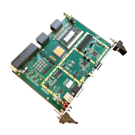
Page 12: Figure 3-2: Gr-Vpx-Gr740 Main Board Without Mezzanine Board
GR-VPX-GR740-BOARD Figure 3-2: GR-VPX-GR740 Main Board without mezzanine board GR-VPX-GR740-BOARD-UM, Nov 2020, Version 1.4 www.cobham.com/gaisler... -
Page 13: Handling
This board is intended for commercial use and evaluation in a standard laboratory environment, nominally, 20°C. All devices are standard commercial types, intended for use over the standard commercial operating temperature range (0 to 70ºC). GR-VPX-GR740-BOARD-UM, Nov 2020, Version 1.4 www.cobham.com/gaisler... -
Page 14: Board Design
MEZZANINE CONNECTOR CONNECTOR RESET & CLOCKS RESET & AUX. RESET & AUX. CIRCUITS CIRCUITS POWER POWER POWER OSCILLATORS OSCILLATORS CIRCUITS CIRCUITS VPX BACKPLANE VPX BACKPLANE CONNECTORS CONNECTORS Figure 4-1: GR-VPX-GR740 Board Board Block Diagram GR-VPX-GR740-BOARD-UM, Nov 2020, Version 1.4 www.cobham.com/gaisler... -
Page 15: Board Mechanical Format
'universal' keys (Part number TE-1-1469492-9), allowing its installation into any slot. These keys can easily be dismounted and replaced with specific key parts if when these are known. GR-VPX-GR740-BOARD-UM, Nov 2020, Version 1.4 www.cobham.com/gaisler... -
Page 16: Figure 4-3: Vpx Style Mechanical Keying
The face to face mounting distance of the two boards is 10mm. While the prototype board is mounted using simple 10mm nickel-brass Hex spacers, a future design could accommodate a custom aluminium bracket to act as a thermal interface between the two boards. GR-VPX-GR740-BOARD-UM, Nov 2020, Version 1.4 www.cobham.com/gaisler... -
Page 17: Figure 4-4: Mezzanine Board Mounted On A Gr-Vpx-Gr740 Main Board
GR-VPX-GR740-BOARD Figure 4-4: Mezzanine board mounted on a GR-VPX-GR740 main board GR-VPX-GR740-BOARD-UM, Nov 2020, Version 1.4 www.cobham.com/gaisler... -
Page 18: Gr740 Microcontroller
The board incorporates a large number of SpaceWire Links distributed between the VPX backplane, GR740 Processor, mezzanine connector, External Front panel connectors and an on board header/connector. The on-board SPW network is represented in the figure below. GR-VPX-GR740-BOARD-UM, Nov 2020, Version 1.4 www.cobham.com/gaisler... -
Page 19: Figure 4-5: On-Board Spacewire Connections
GR740 SPW router Backplane SpW Interface port number PORT 3 SPW_PL1R_CP PORT 4 SPW_PL2N_CP PORT 5 SPW_PL3R_CP PORT 6 SPW_PL2R_CP PORT 7 SPW_PL1N_CP PORT 8 SPW_PL3N_CP Table 2: GR740 SpW Router Port mapping to Backplane interfaces GR-VPX-GR740-BOARD-UM, Nov 2020, Version 1.4 www.cobham.com/gaisler... -
Page 20: Spw Connector Implementation Details And Precautions To Follow
MIL-STD-1553 / MIL-STD-1760 specifications. The configuration on the board is intended for 'transformer coupling'. For a 'direct coupling' interface to external equipment external 55 Ohm series resistors would be GR-VPX-GR740-BOARD-UM, Nov 2020, Version 1.4 www.cobham.com/gaisler... -
Page 21: Pps
SPW connections over the Data Plane and Control planes. This requires many resistors to be installed or removed depending on which configuration is required to be implemented. For details, refer to the schematic diagrams [RD3]. GR-VPX-GR740-BOARD-UM, Nov 2020, Version 1.4 www.cobham.com/gaisler... -
Page 22: Mezzanine Interfaces
9 General purpose I/O from the GR740 (MPIO signals 1 – 9) ◦ Note the GPIO (MPIO) signals are also shared with bootstrap functionality (see Table 6). • RESETN from main board reset circuit • SYSCON# and SYSCONP# from VPX backplane GR-VPX-GR740-BOARD-UM, Nov 2020, Version 1.4 www.cobham.com/gaisler... - Page 23 ◦ The PCI clock must be provided from the mezzanine board. ◦ The PCI specification requires that the following system signals are pulled- PCI_FRAME, PCI_STOP, PCI_PAR, PCI_IRDY, PCI_PERR, PCI_TRDY, PCI_SERR and PCI_DEVSEL. These signals must be pulled up in the mezzanine board. GR-VPX-GR740-BOARD-UM, Nov 2020, Version 1.4 www.cobham.com/gaisler...
-
Page 24: Gpio
PPS input to GR740 GPIO1 MPIO1 GPIO to mezzanine connector GPIO2 MPIO2 GPIO to mezzanine connector GPIO3 MPIO3 GPIO to mezzanine connector GPIO4 MPIO4 GPIO to mezzanine connector GPIO5 MPIO5 GPIO to mezzanine connector GR-VPX-GR740-BOARD-UM, Nov 2020, Version 1.4 www.cobham.com/gaisler... -
Page 25: Table 3: Functions Assigned To Gpio Signals Of Gr740
GPIO11 FPIO1 Front panel J5 GPIO12 FPIO2 Front panel J5 GPIO13 FPIO3 Front panel J5 GPIO14 FPIO4 Front panel J5 GPIO15 FPIO5 Front panel J5 Table 3: Functions assigned to GPIO signals of GR740 GR-VPX-GR740-BOARD-UM, Nov 2020, Version 1.4 www.cobham.com/gaisler... -
Page 26: Table 4: Functions Assigned To Gpio2 Signals Of Gr740
S24 is set to (C-3) BPIO6 if SP3T switch BPIO6 controls S24 is set to (C-1) GPIO2_14 Not available as GPIO GPIO2_15 Not available as GPIO Table 4: Functions assigned to GPIO2 signals of GR740 GR-VPX-GR740-BOARD-UM, Nov 2020, Version 1.4 www.cobham.com/gaisler... -
Page 27: Figure 4-7: Configuration Option For Switch S23 And S24
GR-VPX-GR740-BOARD Figure 4-7: Configuration option for switch S23 and S24 Figure 4-8: Configuration option for switch S27 to S41 GR-VPX-GR740-BOARD-UM, Nov 2020, Version 1.4 www.cobham.com/gaisler... -
Page 28: Debug Support Unit Interfaces
Debug Support Unit Interfaces Program download and debugging to the GR740 processor is performed using the GRMON Debug Monitor tool from Cobham Gaisler ([RD2]). The GR740 processor provides an interface for Debug and control of the processor by means of a host terminal via its DSU interface, as represented in Figure 4-9. -
Page 29: Oscillators And Clock Inputs
LVDS output. The AUX_CLK is a differential LVDS output which can be generated either as a copy of the 1PPS input pulse, or via a jumper from an output of the FPGA on the mezzanine. GR-VPX-GR740-BOARD-UM, Nov 2020, Version 1.4 www.cobham.com/gaisler... -
Page 30: Figure 4-10: Board Level Clock Distribution Scheme - Gr-Vpx-Gr740
REF_CLK1 REF_CLK1 LVDS REF_CLK2 REF_CLK2 LVDS REF_CLK REFCLK_OUT LVDS JP11 PPS_OUT AUX_CLK LVDS JP10 PPS_IN VPX BACKPLANE VPX BACKPLANE CONNECTORS CONNECTORS PPS Input (front panel) Figure 4-10: Board level Clock Distribution Scheme – GR-VPX-GR740 GR-VPX-GR740-BOARD-UM, Nov 2020, Version 1.4 www.cobham.com/gaisler... -
Page 31: Power Supply And Voltage Regulation
PERIPHERALS 12V nom 14.5V max +3V3 VDIG_3V3 +3V3 DCDC TPS54527 5A max VDIG_2V5 +2V5 +2V5 GR740 DCDC TPS54527 5A max +1V2 +1V2 VCORE DCDC TPS54527 5A max Figure 4-11: Power Regulation Scheme – GR-VPX-GR740 GR-VPX-GR740-BOARD-UM, Nov 2020, Version 1.4 www.cobham.com/gaisler... - Page 32 GR-VPX-GR740-BOARD The mezzanine board can receive power at a nominal input voltage of +12V provided from the 12P0V pins of the mezzanine connector. GR-VPX-GR740-BOARD-UM, Nov 2020, Version 1.4 www.cobham.com/gaisler...
-
Page 33: Setting Up And Using The Board
To perform program download and software debugging on the hardware it is necessary to use the Cobham Gaisler GRMON3 debugging software, installed on a host PC (as represented in Figure 4-9). Please refer to the GRMON3 documentation for the installation of the software on the host PC (Linux or Windows), and for the installation of the associated hardware dongle. -
Page 34: Sp3T Switch Description And Configuration Properties
There are forty SP3T configuration switches available onboard. The switch schematics and mapping provided in Figure 5-2 remains the same on all those switches, irrespective of the position or the naming convention of the switch. GR-VPX-GR740-BOARD-UM, Nov 2020, Version 1.4 www.cobham.com/gaisler... -
Page 35: Gr740 Bootstrap Signals
These signals are set using the Single pole 3 position miniature switches. These switches can be set with a fine-bladed screwdriver. These 3 position switches have the possibility to set the signal value to 'pull-up' (='high') (C-3), 'float' (='undefined') (C-2), or 'pull-down (='low') (C-1). GR-VPX-GR740-BOARD-UM, Nov 2020, Version 1.4 www.cobham.com/gaisler... -
Page 36: Figure 5-4: Gr740Sbc Bootstrap Signals Default Configuration
MEM_CLKSEL Select source for Memory clock High (C-3) BYPASS0 Bypass PLL 0 Low (C-1) BYPASS1 Bypass PLL 1 Low (C-1) BYPASS2 Bypass PLL 2 Low (C-1) IGNLOCK Ignore PLL Lock status High (C-3) Table 5: GR740 Bootstrap Settings GR-VPX-GR740-BOARD-UM, Nov 2020, Version 1.4 www.cobham.com/gaisler... -
Page 37: Other Configurable Switches Default Settings
GR740 Table 7: Other configurable switches default settings Jumper configurations The default status of the Jumpers on the boards is as shown in Table 8. (Other configurations may be defined by the user). GR-VPX-GR740-BOARD-UM, Nov 2020, Version 1.4 www.cobham.com/gaisler... -
Page 38: Default Setting Of Jumpers - Gr-Vpx-Gr740
Configuration options for Versaclock PLL ranges JP14 Not installed VC1-PROG, do not install for parameters to be loaded via I2C JP15 Installed VC1-CLKSEL; XTAL generates 25MHZ clock Table 8: Default Setting of Jumpers – GR-VPX-GR740 GR-VPX-GR740-BOARD-UM, Nov 2020, Version 1.4 www.cobham.com/gaisler... -
Page 39: Interfaces And Configuration
GR-VPX-GR740-BOARD Interfaces and Configuration Figure 6-1: Front Panel View (pins 1 marked red) GR-VPX-GR740-BOARD-UM, Nov 2020, Version 1.4 www.cobham.com/gaisler... -
Page 40: List Of Connectors - Gr-Vpx-Gr740
Table 9: List of Connectors – GR-VPX-GR740 List of Connectors – GR-VPX-SPW-MEZZ Name Function Type Description SPW-1 MDM_9S SpaceWire interface GR740 ROUTER PORT 2 SPW-0 MDM_9S SpaceWire interface GR740 ROUTER PORT 1 Table 10: List of Connectors – GR-VPX-SPW-MEZZ GR-VPX-GR740-BOARD-UM, Nov 2020, Version 1.4 www.cobham.com/gaisler... -
Page 41: Table 11: J1 Power - External Power Connector
No connect TPFIN Input -ve TPFIC Input centre-tap No connect Table 13: J3 RJ45-ETHERNET Connector Name Comment INNER Inner Pin, Pulse Per Second,+3V3 logic OUTER DGND Outer Pin Return Table 14: J4 PPS Input GR-VPX-GR740-BOARD-UM, Nov 2020, Version 1.4 www.cobham.com/gaisler... -
Page 42: Table 15: J5: Front Panel Input/Output Pins
GR-VPX-GR740-BOARD CONNECTOR PIN FUNCTION FUNCTION ■ □ FPIO0 FPIO1 □ □ FPIO2 FPIO3 □ □ FPIO4 FPIO5 □ □ FPIO6 FPIO7 □ □ Opt. +3V3 DGND Table 15: J5: Front Panel Input/Output pins GR-VPX-GR740-BOARD-UM, Nov 2020, Version 1.4 www.cobham.com/gaisler... - Page 43 DQ23 DQ47 +3.3V +3.3V A15 (SBA0) DGND DGND A16 (SBA1) +3.3V +3.3V SDDQM2 SDDQM5 pulled high pulled high DGND DGND +3.3V +3.3V DGND DGND SDSDA / pulled high SDSCL / pulled high +3.3V +3.3V GR-VPX-GR740-BOARD-UM, Nov 2020, Version 1.4 www.cobham.com/gaisler...
-
Page 44: Table 16: J6: Sdram Sodimm Socket Pin-Out
JTAG: TMS Table 17: J7 GR740 – JTAG Connector Name Comment VBUS +5V (from external host) Data Minus Data Plus Not used DGND Ground Table 18: J8 USB Micro connector – FTDI Quad Serial Link GR-VPX-GR740-BOARD-UM, Nov 2020, Version 1.4 www.cobham.com/gaisler... -
Page 45: Table 19: J9 Mezzanine Connector - Female
GR-VPX-GR740-BOARD Table 19: J9 Mezzanine Connector – Female GR-VPX-GR740-BOARD-UM, Nov 2020, Version 1.4 www.cobham.com/gaisler... -
Page 46: Table 20: J10 Spw-Hdr Interface Connections
Name Comment F-TCK JTAG: TCK DGND Ground F-TDO JTAG: TDO no connect F-TMS JTAG: TMS VREF 3.3V VPUMP Programming Voltage F-TRSTN JTAG: TRSTN F-TDI JTAG: TDI DGND Ground Table 21: J11 FPGA– JTAG Connector GR-VPX-GR740-BOARD-UM, Nov 2020, Version 1.4 www.cobham.com/gaisler... -
Page 47: List Of Oscillators, Switches And Led's - Gr-Vpx-Gr740
SP3T – sets MEM-CLKSEL to pull-up, float, pull-down BYPASS0 SP3T – sets PLL BYPASS0 to pull-up, float, pull-down BYPASS1 SP3T – sets PLL BYPASS1 to pull-up, float, pull-down BYPASS2 SP3T – sets PLL BYPASS2 to pull-up, float, pull-down GR-VPX-GR740-BOARD-UM, Nov 2020, Version 1.4 www.cobham.com/gaisler... -
Page 48: Table 24: List And Definition Of Switches
Push Button Reset S26-S33 BP0-BP5 SP3T selects Backpanel IO signals – active when BP6 = ‘0’ S34-S41 BP0-BP5 SP3T selects Backpanel IO signals – active when BP6 = ‘1’ Table 24: List and definition of Switches GR-VPX-GR740-BOARD-UM, Nov 2020, Version 1.4 www.cobham.com/gaisler... -
Page 49: Figure 6-2: Gr-Vpx-Gr740 Pcb Top View
GR-VPX-GR740-BOARD Figure 6-2: GR-VPX-GR740 PCB Top View (extract from [RD4] GR-VPX-GR740-BOARD-UM, Nov 2020, Version 1.4 www.cobham.com/gaisler... -
Page 50: Figure 6-3: Gr-Vpx-Gr740 Pcb Bottom View
GR-VPX-GR740-BOARD Figure 6-3: GR-VPX-GR740 PCB Bottom View (extract from [RD4] GR-VPX-GR740-BOARD-UM, Nov 2020, Version 1.4 www.cobham.com/gaisler... - Page 51 GR-VPX-GR740-BOARD GR-VPX-GR740-BOARD-UM, Nov 2020, Version 1.4 www.cobham.com/gaisler...
-
Page 52: Change Record
Details of the new mezzanine board (GR-VPX-SPW-MEZZ which provides two SpaceWire interfaces in the Front panel) are included. Table 8 Jumper JP12 installed by default, to to provide 3V3 from Main Board to Mezzanine GR-VPX-GR740-BOARD-UM, Nov 2020, Version 1.4 www.cobham.com/gaisler... - Page 53 Cobham; nor does the purchase, lease, or use of a product or service from Cobham convey a license under any patent rights, copyrights, trademark rights, or any other of the intellectual rights of Cobham or of third parties.
Need help?
Do you have a question about the GR-VPX-GR740-BOARD and is the answer not in the manual?
Questions and answers