Table of Contents
Advertisement
Quick Links
Advertisement
Table of Contents

Related Manuals for Mountz TorqueLab


Summary of Contents for Mountz TorqueLab
- Page 1 â â â â A n a l y z e r mountz the torque tool specialists...
-
Page 2: Table Of Contents
T A B L E O F C O N T E N T IMPORTANT PRECAUTIONS ………………………………………………………………...……… 3 WARRANTY ………………………………………………………………...………………..… 3 FEATURES OVERVIEW ……………………………………………………………………...……….. 4 MOUNTING ………………………………………………………………..……………………….…… 5 EXTERNAL CONNECTIONS …………………………………………………………...…..………… 6 USER INTERFACE ………………………………………………………………...……………...…… 7 DISPLAY ……………………………………………………………….…………….…...…… 7 KEYPAD ……………………………………………………………………….……….……… 7 CLEARING THE DISPLAY ………………………………………………………………………….…... -
Page 3: Important Precautions
(1) year from the date of sale, the tool will be repaired free of charge if returned to Mountz, Inc. This warranty is not valid if the tool has been misused, tampered with or abuse. Any questions pertaining to Warranty Repair or Returns should be directed to Mountz Customer Service department. -
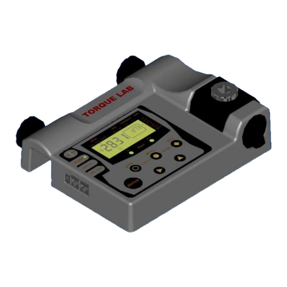
Page 4: Features Overview
F E A T U R E S O V E R V I E W Controlling torque is quintessential for companies to ensure their product' s quality, safety and reliability isn't compromised. Insufficiently torqued fasteners can vibrate loose overtime and when excessively torqued the threaded fasteners can strip. Using a quality torque analyzer has become increasingly important for many companies to secure that proper torque is being applied. -
Page 5: Mounting
It is strongly recommend securing the analyzer to a workbench before operating. Immobilizing the analyzer is critical for the safety the operator as well as for the accuracy of torque measurements during operation. The TorqueLabâ features two mounting options. SURFACE MOUNT This mounting option offers the most secure way to immobilize the analyzer, and is recommended when used at a permanent location. -
Page 6: External Connections
Rated Output between 1.7 to 2.3 mV/V and 5 V. See “CELL SET-UP”. TRANSDUCER and RS 232 CONNECTION PIN-OUT The following diagram and Table define the pins of the I/O connectors for the TorqueLabâ. RS-232 Connector Transducer Connector... -
Page 7: User Interface
U S E R I N T E R F A C E DISPLAY Three modes of Displays which When tolerance parameters are Select among operation for set, "High" or "Low" will flash if seven measuring transducer in use units. measuring torque torque is outside the parameters Small window:... -
Page 8: Clearing The Display
S L E E P M O D E The TorqueLabâ features a built-in sleep mode function to save power when not in use. If there is no activity for 5 minutes, such as key press or no torque input, the analyzer will display SLP. -
Page 9: Go / No Go Signal
G O / N O G O S I G N A L The TorqueLabâ is equipped with visual (green and red LED) and audible (buzzer) signals to provide the user instant torque status during operation. These signals operate in conjunction with the transducer’s capacity and tolerance settings. -
Page 10: Printing / Downloading Data
P R I N T I N G / D O W N L O A D I N G D A T A Data output is available, from the TorqueLabâ, via the RS232 port. The analyzer only outputs displayed torque values. These values can be directly printed by any serial printer or downloaded into a computer. -
Page 11: Mode Selection
Text”. Then select the folder and file you wish to save it as. M O D E S E L E C T I O N The TorqueLabâ Analyzer offers three different modes for displaying torque information during operation. The user will determine which mode is best suited for the application. -
Page 12: Unit Selection
The TorqueLabâ analyzer supports seven units of torque measurement, lbf.ft, lbf.in, ozf.in, N.m, cN.m, Kgf.m, and kgf.cm. However certain torque values cannot be converted into other units due to display resolution, in these cases the TorqueLabâ will warn you by displaying “Err”. Key sequence to change units: •... -
Page 13: Set-Up Menu
S E T - U P M E N U The following is a quick reference for the Set-Up menu structure. If lost within the menu, you can turn the analyzer OFF and ON at any time. Key Function: Set-Up (Mode + Unit) to access the menu Scroll Up to navigate through the menu options or to select values Scroll Right... -
Page 14: Tolerance Set-Up
T O L E R A N C E S E T - U P The Tolerance parameters control the Go and No-Go signal response (see Go / No Go Signal section). The user sets a lower and upper torque thresholds to get a visual and audible warning signals when these limits are reached or breached during operation. -
Page 15: Filter Set-Up
RS 232 port before clearing (see Printing / Downloading Data section). F I L T E R S E T - U P The TorqueLabâ offers a selection of four different Low Pass Filters. These filters are used to eliminate unwanted noise, most often occurring during operation of power tools. -
Page 16: Calibration Set-Up
C A L I B R A T I O N S E T - U P Equipment and methods used during the calibration process of any transducers or analyzers are critical and can dramatically affect the quality, accuracy and performance of your analyzer. Maintain all your calibration equipment in top condition, and always perform the calibration process in a controlled environment. -
Page 17: Low Capacity
Note: The decimal point is now at a fixed location, previously determined during the HIGH CAPACITY set-up. RATED OUTPUT The TorqueLabâ can accept a rated output ranging Data from 1.700 to 2.300 mV/V and 5 V (Brushless transducers). This value is provided by the... -
Page 18: True Calibration
C A L I B R A T I O N S E T - U P C o n t i n u e s … TRUE CALIBRATION This method is based on an eight-point calibration system to compensate for a transducers nonlinearly. - Page 19 The TorqueLabâ â â â , and the Mountz family of transducers have been designed to minimize these variations and are well suited for both the analysis of the application joint and the testing of the impulse tool.
- Page 20 (highly recommended). For manual calibration of click type wrenches use the First Peak mode on the TorqueLabâ so the tester will display the point at which the wrench “clicked” (First Peak) and the point when the operator stopped pulling (Second Peak shown in the torque window).
Need help?
Do you have a question about the TorqueLab and is the answer not in the manual?
Questions and answers