Sign In
Upload
Manuals
Brands
Digital Dream Manuals
Controller
DDCS-Expert
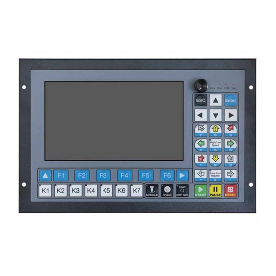
User Manuals: Digital Dream DDCS-Expert Controller
Manuals and User Guides for Digital Dream DDCS-Expert Controller. We have
1
Digital Dream DDCS-Expert Controller manual available for free PDF download: User Manual
Digital Dream DDCS-Expert User Manual (83 pages)
Standalone Motion Controller
Brand:
Digital Dream
| Category:
Controller
| Size: 9 MB
Table of Contents
Table of Contents
2
DDCS-Expert Brief Introduction
4
Product Brief Introduction
4
DDCS-Expert Brief Technical Feature
5
Appearance, Structure and Size of Product
6
(DDCSE) Side View and Dimensions
6
Front Panel
7
Back Side of the Controller
7
Explanation of Abbreviations
8
Notes and Warnings
8
Controller Panel and Operation
9
DDCS-Expert (DDCSE) Controller Panel
9
Input and Output Ports
11
IO Page
11
The Input and Output Port Definitions
12
FOR Output Port
13
Input 01 Is Conducting with COM-
14
The Status Is Active but IN01 Is Not on
14
The Signal Is Not Active but Port in Conducting
15
MPG Input Page
15
Wiring Board Overview
16
Controller Wiring Ports Overview
16
Wiring Diagram Overview
17
Power Supply Input
19
Power Supply Wiring Methods
19
How the IO Power Gives Power to the Input Ports
19
How the IO Power Gives Power to the Output Ports
20
The Power Supply Wiring Methods
20
Spindle Wiring
21
Analog Spindle
21
Spindle Wiring Methods
21
Spindle Wiring Example
22
Servo Spindle (PLUSE/DIRECTION)
23
Multi-Speed Spindle
23
Relationship between Multi-Speed Section and Spindle Section Output
23
The Relationship between the Current Section and Output Status
23
The Wiring for the Multi-Speed Spindle
24
Relay Wiring
25
If Relay Power Supply Is 24VDC
25
If Relay Power Supply Is Not 24VDC
25
Stepper /Servo Driver Wiring
26
Pluse and Direction Signal Wiring Methods
26
Wrong Wiring of Pulse and Direction
26
Stepper/Servo Driver Connect with DDCS Expert
27
Limit, Home and Probe Inputs
28
Proximity Switch/Mecahnical Switch and Normal Probe Wiring Methods
28
The Probe Sensor with Over-Strock Alarm Signal
28
The Wiring Methods of Probe Sensor with Over-Strock Signal
29
External Buttons
30
MPG Wiring
30
The Wiring Methods of External Buttons
30
DDCS - Expert Wiring with DDMPG
31
Turnning Wheels in CCW Direction
32
Turnning Wheels in CW Direction
32
Series Port Wiring
33
The MPG Channel Is on X Axis
33
DDCS Expert Wiring with Single-Terminal MPG
33
Series Ports Wiring
33
Softw Are and Operation
34
Software Structure
34
The Main Page of the Software
35
Main Page of Monitor
35
XYZAB Coordinate
36
Status
36
Feed Status
36
Operating Status
36
Fro
37
Sro
37
Sjr/Jog Step
37
Feed Speed
37
Cur Tool
38
Total No.
38
Cur No.
38
Cycle Times
38
FRO: Feed Rate Override
39
Sro
39
When the Percent Number Is Blue,We Can Edit SRO
40
When the Percent Number Is Blue,We Can Edit SJR
40
In Jog Step Mode
41
Define Distance
41
Input Number
41
New Distance Active
41
Feed Rate
42
Shift to Feedrate Column
42
Ingore F from G-Code File
42
Feedrate Value Is Active
42
Set the Default Feed Rate
43
Write in the Value
43
The New Feed Rate Value Already Set
43
Analog S/Ser Vo S/Multi-Speed
44
3 Different Spindle Modes
44
Spindle in Analog Mode
44
Spindle in Pul/Dir Mode
44
Shift to Analog S Column
45
Ingore S from G-Code File
45
Analog S Value Is Active
45
Ingore Analog S Value
45
Set the Default Spindle Speed
46
The New Spindle Speed Setting Is Done
46
Simulation
47
Simulation Page
47
Simulate a G-Code File
48
System Is in Simulation
48
Simulation Finished
49
Floating Probe
50
Star to Floating Probe
51
Floating Probe Finished
51
Fixed Probe
52
Type in the Tool Number and Enter
53
Fixed Probe Finished
53
Go Work Zero
54
Sub-Page of Go Work Zero
54
Go Home
55
All Axis Go Zero
55
Home Finished Symbol
57
Mach Postion after Home
57
System Ask if Go to Home When Power on
57
Clear
58
Sub-Page of CLEAR
58
Break Run
59
Clear All Axis
59
“Break Run” Page
59
Start from a Specific Line
60
Input the Line Number
60
Breakpoint Line No.
60
Manual
61
Manual Page
61
Coord Set
63
First Page of Coord Set
63
Select Coord
64
Current Coordinate Is G54
64
Clear X / y / Z / 4Th / 5Th Axis
65
Select the Coordinate to G57
65
Clear X in Coordinate 57
65
Set Z Step
66
Deeper and Move up
66
MDI
67
MDI Page
67
Vitual Keyboard Is Enabled by “Enter”
68
Edit a Line of G-Code
68
Edit a Line of G-Code with Another Vitial Keyboard
68
Middle
70
Middle Page
70
DDCS-Expert Controller Can Support Two Kinds Function
70
Find Middle Point in X Axis
71
First Point Saved
72
Find Middle Point in y Axis
73
Find a Middle Point for the Arc
75
Middle Arc Page
75
First Point Position Is Saved
76
The Second Point Position Is Saved
77
Find Middle for the Arc
77
First Pts
78
Second Pts
78
Third Pts
78
Center Pts
78
Work Record
79
“Work Record” Page
79
Clear the Working Record
80
Sort Process
81
Import the G-Code Files from the Local Disk
82
The G-Code Files Imported in
82
Advertisement
Advertisement
Related Products
Digital Dream DM500
Digital Dream DM500T3
Digital Dream DDCS V2.1
Digital Dream DDCS V3.1
Digital Dream EC500
Digital Dream NCH02
Digital Dream UC300
Digital Dream Categories
Controller
Digital Camera
More Digital Dream Manuals
Login
Sign In
OR
Sign in with Facebook
Sign in with Google
Upload manual
Upload from disk
Upload from URL