
Related Manuals for TEKTROL TEK-B AR 3120B


Summary of Contents for TEKTROL TEK-B AR 3120B
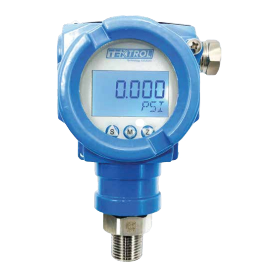
- Page 1 Technology Solutions AR 3120B Exp Absolute/Gauge Pressure Transmitter Instruction Manual Document Number: IM-3120B www.tek-trol.com...
- Page 2 www.tek-trol.com NOTICE Read this manual before working with the product. For personal and system safety, and for optimum product performance, make sure you thoroughly understand the contents before installing, using, or maintaining this product. For technical assistance, contact Customer Support 796 Tek-Drive Crystal Lake, IL 60014 Tel: +1 847 857 6076...
-
Page 3: Table Of Contents
Table of Contents Safety Instructions ........................... 3 Intended Use ............................3 Certifications ............................3 Safety Instructions from the Manufacturer ....................3 1.3.1 Disclaimer ..............................3 1.3.2 Product Liability and Warranty ........................3 1.3.3 Information Concerning the Documentation ....................3 Safety Precautions ..........................3 Packaging, Transportation and Storage .................... - Page 4 3.5.6 Open Container Level Measurement: Single Flange Level Transmitter ............. 14 3.5.7 Sealed Container Level Measurement: Single Flange Level Transmitter ........... 15 Electrical Connections........................15 Grounding of Measuring Device ......................15 Power Supply Specifications and Connection ..................16 Cable Protection System ........................17 4.3.1 Standard Protection System ........................
-
Page 5: Safety Instructions
1 Safety Instructions 1.1 Intended Use Tek-Bar 3120B is a Exp Absolute/Gauge Pressure Transmitter used for pressure and level measurement of steam, liquids and Gasses. The manufacturer is not liable for damage caused by improper or non-designated use. 1.2 Certifications Tek-Bar 3120B has CE, CSA approval (Class I Div. -
Page 6: Packaging, Transportation And Storage
Warnings and Symbols Used The following safety symbol marks are used in this operation manual and on the instrument. WARNING Indicates a potentially hazardous situation which, if not avoided, could result in death or severe injury CAUTION Indicates a potentially hazardous situation which, if not avoided, may result in minor or moderate injury. -
Page 7: Transportation
1.5.2 Transportation • Avoid impact shocks to the device and prevent it from getting wet during transportation. • Verify local safety regulations, directives, and company procedures with respect to hoisting, rigging, and transportation of heavy equipment. • Transport the product to the installation site using the original manufacturer’s packing whenever possible. -
Page 8: Product Description
2 Product Description This specification covers the reference and specification data, as well as ordering information. 2.1 Introduction Tek-Bar 3120B Exp Absolute/Gauge Pressure Transmitter utilizes world’s leading mono crystal silicon pressure sensor technology. It can handle rigorous industrial applications and it can withstand extreme chemical, mechanical and electrical working conditions. -
Page 9: Specifications
2.3 Specifications 2.3.1 General Specification Pressure Type Gauge or Absolute Accuracy ±0.075% F.S. (Optional ± 0.04%F.S.) Diaphragm Materials Hastelloy C Measuring Range 5 to 10000psig (5 to 1500psig) Stability ±0.2 % URL/5 year Process Connections ½” MNPT (other options available) Wetted material 316L SS and Hastelloy C Working Humidity... -
Page 10: Dimensional Drawings
2.3.5 Measuring Range Limit Smallest Calibrated Lower Range Upper Range Nominal Value Overload Limit Span Limit (LRL) Limit (URL) 5psi 8 in.WC -14.5psi 5psi 145psig 36psi 2psi -14.5psi 36psi 580psig 145psi 7.25psi -14.5psi 145psi 870psig 435psi 22.25psi -14.5psi 435psi 2175psig 1500psi 72.5psi -14.5psi... -
Page 11: Model Chart
2.5 Model Chart Example Tek-Bar 3120B G-A 3 WP Tek-Bar 3120B-G-A-3-WP-1-HC-1-BA Series Tek-Bar 3120B Exp Absolute/Gauge Pressure Transmitter Gauge Pressure Types Absolute Pressure 0 to 5psi (G or A) (40:1 Turndown, Adj. Range: -5 to 5psi) 0 to 36psi (G or A) (40:1 Turndown, Adj. Range: -14.5 to 36psi) 0 to 145psi (G or A) (40:1 Turndown, Adj. -
Page 12: Selecting The Installation Location
3.1 Selecting the Installation Location Prior to product installation, check the model, specifications and installation location for the transmitter. The transmitter is designed to withstand severe environmental conditions. However, follow the enlisted precautions while selecting the installation site to ensure stable and accurate operation for years. -
Page 13: Housing Rotation
Choose gasket according to the properties of the process medium and the temperature range. Pay attention to the bolt balance lock. 3.2.2.3 Clamp Connection Choose gaskets that meet specified standards to avoid excessive clamp locking and squeezing gasket. Excessive locking of clamp may damage the sensing diaphragm and cause measuring error. -
Page 14: Mounting Requirements
3.2.6 Conduit Installation Improper sealing of connections may damage the transmitter due to excess moisture accumulation. Mount the transmitter with electrical housing positioned downward so that the excess of moisture is condensed and drained out from the casing. Secondly, install wiring with a drip loop and ensure the bottom of the drip loop is mounted lower than the conduit connections or the transmitter housing to avoid moisture accumulation in the housing. -
Page 15: Field Adjustment
3.3.3 Steam Measurement Place taps to the side of the line. • • Mount the transmitter below the taps to ensure that the impulse piping stays filled with condensate. In steam service above 250°F (121°C), fill impulse lines with water to prevent the direct steam •... -
Page 16: Product Usage
3.4.2 Full Span Adjustment • For full span adjustment, ensure that the vessel is filled with process medium to the maximum level. • Maintain static pressure value within the minimum and maximum pressure range. • Using local push buttons set output for lower and upper limit of the full scale i.e., 4mA and 20mA, refer to section 5.2 of this manual for detailed key operations. -
Page 17: Sealed Container Level Measurement: Single Flange Level Transmitter
For accurate measurement, install the transmitter at a location where liquid level and temperature fluctuations are minimal. 3.5.7 Sealed Container Level Measurement: Single Flange Level Transmitter Use a single flange diaphragm system for sealed container level measurement. Increase the isolation tank and multiple shut-off valves. Periodically open the drain/vent valve to clear off the residual gas and liquid in the guiding pressure tube for higher accuracy. -
Page 18: Power Supply Specifications And Connection
Power Supply Specifications and Connection • Use independent linear direct current power supply for pressure transmitter. Large resistive load results in high pressure drop. • Therefore, it is recommended to consider the resistance across the signal cable, display meter and other equipment to ensure sufficient voltage is provided to the pressure transmitter for its normal operation. -
Page 19: Cable Protection System
4.3 Cable Protection System Apply following cable protection measures to protect the connecting cables from various factors that affect negatively on the cable lifetime. 4.3.1 Standard Protection System • To avoid liquid flowing along with the cable into the terminal box, configure a U-shaped ring between pull box and pressure transmitter as shown in the figure below. -
Page 20: Operation
5 Operation This section covers operation techniques and guidelines along with the configuration and calibration. NOTE Calibrate the instrument according to the instructions given in this section, otherwise it could lead to measurement error. 5.1 Local Operation and Display Tek-Bar 3120B is available with the optional LCD display. The local display enables user to read important parameters directly at the measuring point and configure the device using the function matrix. -
Page 21: Configuration
5.3 Configuration This section provides detailed information of initial setup required for transmitter functioning. The device consists of 3 operation key: S, Z and M which are used to set parameters and perform various operations. The primary function of each key is mentioned as below. Z: Enter the setting operations S: Modify the parameter value M: Confirm the set value and enter the next menu... - Page 22 www.tek-trol.com...
-
Page 23: Detailed Operating Instructions
5.4.2 Detailed operating instructions. www.tek-trol.com... -
Page 24: Modbus Programming Menu
5.5 Modbus Programming Menu 5.5.1 Key Operation www.tek-trol.com... -
Page 25: Detailed Operating Instructions
5.5.2 Detailed operating instructions www.tek-trol.com... - Page 26 CAUTION Products without 4-20mA output, FIXC, AOLC, AOHC do not display. NOTE 1. FIXC is to control fixed current output of products, to check whether output circuit of product current is normal. Modify fixed current value by pressing S key and confirm with Z key. 2.
-
Page 27: Flow Diagram
5.6 Flow Diagram Refer the following flow diagram to configure various parameter. Use parameter table to know the possible range of values and units. Measuring Smart Interface 5.457 Confirm and enter the next menu Enter settings Modify parameters Set parameters Display modified Current parameters parameters... - Page 28 Table 1: Parameter Table Parameter Values Percentage Display mode Process variable Current mmHg Units Use the keys Z() and S() to inHg change the units TORR mbar g/cm Kg/cm Lower and Upper range -19999 to 99999 Damping time 0 ~ 100 s √...
-
Page 29: Handheld Communicator
5.7 Handheld Communicator If custom display is not available, then configure transmitter parameter using communicator. Decimal point position, Upper range value, Lower range value, Engineering units are configured. See the below flow chart. -
Page 30: Maintenance
Instruction Manual Tek-Bar 3120B Technology Solutions 6 Maintenance This section covers maintenance techniques and guidelines. WARNING Explosion can result into a serious injury or death. • Do not remove the transmitter cover in explosive environments when the circuit is live. •... -
Page 31: Depot Repair
Instruction Manual Tek-Bar 3120B Technology Solutions 6.1.4 Depot Repair Execute following steps before sending the device for depot repair: • Disconnect the transmitter carefully. Preserve all accessories and cables for reassembling. • Remove the harmful residues such as inflammable, poisonous, cancer genic and radioactive substances. -
Page 32: Symptoms And Corrective Measures
Instruction Manual Tek-Bar 3120B Technology Solutions 7.1 Symptoms and Corrective Measures Refer to the table below to verify whether the transmitter hardware and process connections are in good working condition: Symptom Potential Source Corrective Action Check for a minimum of 250Ω resistance between the power supply and HHT. -
Page 33: Tek-Bar 3120B Exp Absolute/Gauge Pressure Transmitter Lcd Display Error Codes
Instruction Manual Tek-Bar 3120B Technology Solutions Check for adequate voltage to the transmitter. The transmitter always requires 11.9 to 45 VDC. Check for intermittent shorts, open Loop Wiring circuits, and multiple grounds. Check polarity of signal terminal Check the loop impedance. Connect HHT and check the sensor limits to ensure calibration adjustments Electronics Module... - Page 34 Sales: +31 76-2031908 Sales: +971-6526-8344 Support: +1 847-857-6076 Email: tektrol@tek-trol.com www.tek-trol.com Tek-Trol is a fully owned subsidiary of TEKMATION LLC. We o er our customers a comprehensive range of products and solutions for process, power and oil & gas industries. Tek-Trol provides process measurement and control products for Flow, Level, Temperature &...
Need help?
Do you have a question about the TEK-B AR 3120B and is the answer not in the manual?
Questions and answers