Advertisement
INTERFACE SERIES
Installation & Operation Instructions
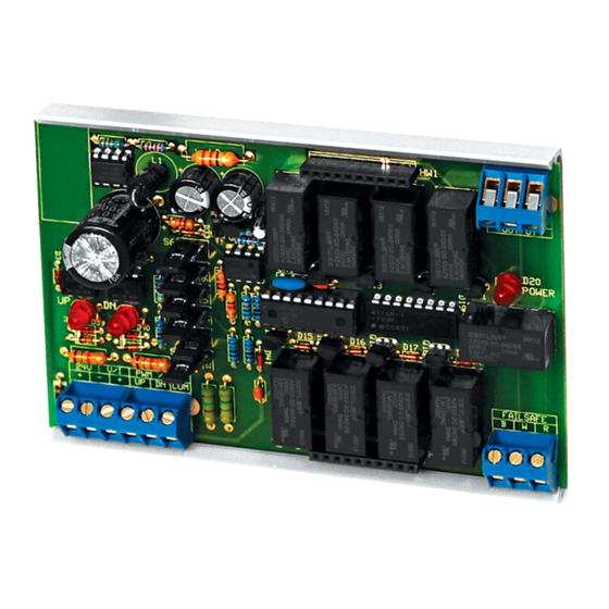
DRN3.1
GENERAL INFORMATION
The DRN3.1 is an interface device that allows
microprocessor control of a variable resistance. The
DRN3.1's isolated resistor network can be
controlled by several di erent DDC signal types. It
directly replaces a variable resistance controller and
simulates the action of a slide wire or rotary
potentiometer. All connections of the simulated
potentiometer, the wiper, and both ends of the
resistance range are available on the terminal strip.
The DRN3.1 must be ordered with a Resistance
Network. The DRN3.1 accepts Analog, Pulse, or
Floating Point input signals (including triac) and
converts them into a proportional resistive output.
The output resistance does not wrap around if the
input signal exceeds the highest or lowest selected
input value. Custom resistance ranges are available
upon request. The DRN3.1 has on-board fail-back
relays that lock out the original resistive signal
during operation. However, if the supply power is
lost, control of the circuit will revert back to the
original controller signal. An easy local override can
be made by placing a xed (or variable) resistor
between W and R Fail-safe terminals. Jumper inputs
can be speci ed to have the factory set them. This
will speed up installation time for the end user.
MOUNTING INSTRUCTIONS
Circuit board may be mounted in any position. If circuit board slides out of snap track, a non-conductive
"stop" may be required. Use only ngers to remove board from snap track. Slide out of snap track or push
against side of snap track and lift that side of the circuit board to remove. Do not flex board or use tools.
WIRING INSTRUCTIONS
PRECAUTIONS
• Remove power before wiring. Never connect or disconnect wiring with power applied.
•
When using a shielded cable, ground the shield only at the controller end. Grounding both
ends can cause a ground loop.
• It is recommended you use an isolated UL-listed class 2 transformer when powering the unit
with 24 VAC. Failure to wire the devices with the correct polarity when sharing transformers may
result in damage to any device powered by the shared transformer.
• If the 24 VDC or 24VAC power is shared with devices that have coils such as relays, solenoids, or
other inductors, each coil must have an MOV, DC/AC Transorb, Transient Voltage Suppressor (ACI
Part: 142583), or diode placed
Automation Components, Inc.
2305 Pleasant View Road | Middleton, WI 53562
Phone: 1-888-967-5224 | Website: workaci.com
FIGURE 1: DIMENSIONS
BOARD
3.22"
(81.91mm)
SNAP TRACK
3.25" (82.55mm)
Page 1
Phone: 1-888-967-5224
Website: workaci.com
5.00"
(127.00mm)
4.69"
(119.13mm)
.70"
(17.78mm)
Version: 6.0
I0000475
Advertisement
Table of Contents

Subscribe to Our Youtube Channel
Related Manuals for aci DRN3.1


Summary of Contents for aci DRN3.1
- Page 1 • If the 24 VDC or 24VAC power is shared with devices that have coils such as relays, solenoids, or other inductors, each coil must have an MOV, DC/AC Transorb, Transient Voltage Suppressor (ACI Part: 142583), or diode placed Page 1 Automation Components, Inc.
-
Page 2: Version Identification
CALIBRATION VERSION IDENTIFICATION Most DRN3.1’s are shipped as version #1. An IC chip on the DRN3.1 is labeled with the version program number. Make sure you have the correct version. You may have to remove the resistor network card to view and compare to Table 1 (pg. - Page 3 Insert the RN (usually in a separate package from DRN3.1) into the DRN3.1. The HW3 pin on the Resistor Network card should be oriented towards the top as shown on Page 1. There are two rows of pins on the RN and two rows of female connections on the DRN3.1.
- Page 4 (this is your jumper wire #2). You are now ready to simulate a timed pulse signal. For testing purposes, select 0.1 to 25.5 or 0.1 to 10 seconds on version 2. Be sure to reset power to allow the DRN3.1 to recognize new settings.
-
Page 5: Testing The Output
DRN3.1 (i.e.: Do not run signal wiring near line voltage wiring or orescent light xtures). Versions 1 and 2 of the DRN3.1 were modi ed in 2001 to add extra ltering to the input. Time response full scale is about 6 seconds. -
Page 6: Product Specifications
Agency Approvals: RoHS2, WEEE WARRANTY The DRN 3.1 Series is covered by ACI’s Two (2) Year Limited Warranty, which is located in the front of ACI’S SENSORS & TRANSMITTERS CATALOG or can be found on ACI’s website: www.workaci.com. Page 6 Automation Components, Inc. - Page 7 NOTES Page 7 Automation Components, Inc. Version: 6.0 2305 Pleasant View Road | Middleton, WI 53562 I0000475 Phone: 1-888-967-5224 | Website: workaci.com...
- Page 8 Automation Components, Inc. 2305 Pleasant View Road Middleton, WI 53562 Phone: 1-888-967-5224 Website: workaci.com Page 8 Automation Components, Inc. Version: 6.0 2305 Pleasant View Road | Middleton, WI 53562 I0000475 Phone: 1-888-967-5224 | Website: workaci.com...
Need help?
Do you have a question about the DRN3.1 and is the answer not in the manual?
Questions and answers