Advertisement
INTERFACE SERIES
Installation & Operation Instructions
DRN4 - V2
GENERAL INFORMATION
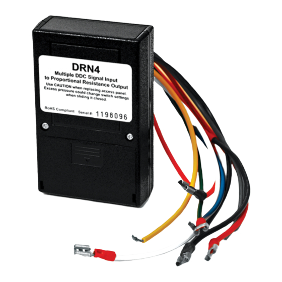
The DRN4 is a resistive output motor actuator
interface that accepts several types of DDC system
signals. The DRN4 output is 0 to 135 ohms. The input
signal types are eld selectable by an 8-position DIP
switch. The oating point input accepts two digital
signals, one for increase and the other for decrease.
The oating point full scale rate of change is 55
seconds. Some triac input signals require an
accessory. The DRN4 is supplied in an enclosure that
can be directly mounted to a 1/2 inch knockout on
the motor actuator. Color coded wire leads with
spade connectors are provided for electrical
connections. Some triac inputs require a Triac
adapter kit.
Johnson Control triac input signal
requires a 1,000 ohm 1/2 watt resistor and is included
with all DRN4s.
MOUNTING INSTRUCTIONS
Tools needed may include a Phillips screwdriver to
remove actuator cover screws, 3 wire nuts for two
signal and one common wire connections and a
voltmeter for troubleshooting if necessary. Turn o
power to the actuator and remove the actuator
cover. Remove a knock-out on the actuator near the
actuator control terminals. Open the access cover on
the DRN4 and set the switches to the desired mode
of operation. Replace the switch access cover on the
DRN4 and remove the outermost lock-nut from the
DRN4 box connector tting. Feed the DRN4 wires
through the actuator knock-out and the lock-nut.
Tighten the lock-nut onto the DRN4 tting. Connect
the DRN4 leads with spade connectors to the correct
actuator terminals, the external control source and
the power source. Wire nut any unused wire and
replace the actuator cover.
PRECAUTIONS
•
Remove power before wiring. Never connect
or disconnect wiring with power applied.
•
When using a shielded cable, ground the
shield only at the controller end. Grounding
both ends can cause a ground loop.
• It is recommended you use an isolated
Automation Components, Inc.
2305 Pleasant View Road | Middleton, WI 53562
Phone: 1-888-967-5224 | Website: workaci.com
FIGURE 1: DIMENSIONS
FRONT
3.80"
(96.47mm)
2.40" (60.91mm)
Top
FIGURE 2: MOUNTING
ACTUATOR
DRN4 CONNECTED
TO ACTUATOR USING
1/2" LOCKNUTS
Page 1
Phone: 1-888-967-5224
Website: workaci.com
Right
1.00"
(25.40mm)
Version: 5.0
I0000633
Advertisement
Table of Contents

Subscribe to Our Youtube Channel
Related Manuals for aci DRN4 - V2


Summary of Contents for aci DRN4 - V2
- Page 1 INTERFACE SERIES Phone: 1-888-967-5224 Installation & Operation Instructions Website: workaci.com DRN4 - V2 FIGURE 1: DIMENSIONS GENERAL INFORMATION The DRN4 is a resistive output motor actuator FRONT Right interface that accepts several types of DDC system signals. The DRN4 output is 0 to 135 ohms. The input signal types are eld selectable by an 8-position DIP switch.
- Page 2 • If the 24 VDC or 24VAC power is shared with devices that have coils such as relays, solenoids, or other inductors, each coil must have an MOV, DC/AC Transorb, Transient Voltage Suppressor (ACI Part: 142583), or diode placed across the coil or inductor. The cathode, or banded side of the DC Transorb or diode, connects to the positive side of the power supply.
- Page 3 FIGURE 4: WIRING Pulse to DRN4 Analog Input to DRN4 Orange (+) 24V Orange 24 VAC (+) 24 VAC or VDC Black (-) Power Power Black (-) Power Supply Controller Yellow Pulsed (+) Signal Yellow Signal 24 VAC (+) Signal Output or VDC Green...
- Page 4 CHECKOUT After DIP switches for the signal input compatible with the external controller are set, power the actuator and have the external controller send a minimum signal and then a maximum command signal to verify proper actuator positioning. The LED under the cover will indicate according to the following: MANUAL OPERATION WITH OVERRIDE BUTTON Manual operation is allowed by placing dip switch (7) in the “OFF”...
- Page 5 -20 to 150°F (-28.9 to 65.5°C) WARRANTY The DRN4 Interface Series is covered by ACI’s Two (2) Year Limited Warranty, which is located in the front of ACI’S SENSORS & TRANSMITTERS CATALOG or can be found on ACI’s website: www.workaci.com.
- Page 6 NOTES Page 6 Automation Components, Inc. Version: 5.0 2305 Pleasant View Road | Middleton, WI 53562 I0000633 Phone: 1-888-967-5224 | Website: workaci.com...
- Page 7 NOTES Page 7 Automation Components, Inc. Version: 5.0 2305 Pleasant View Road | Middleton, WI 53562 I0000633 Phone: 1-888-967-5224 | Website: workaci.com...
- Page 8 Automation Components, Inc. 2305 Pleasant View Road Middleton, WI 53562 Phone: 1-888-967-5224 Website: workaci.com Page 8 Automation Components, Inc. Version: 5.0 2305 Pleasant View Road | Middleton, WI 53562 I0000633 Phone: 1-888-967-5224 | Website: workaci.com...
Need help?
Do you have a question about the DRN4 - V2 and is the answer not in the manual?
Questions and answers