Advertisement
BACnet / Modbus AVERAGING SERIES
Installation & Operation Instructions
GENERAL INFORMATION
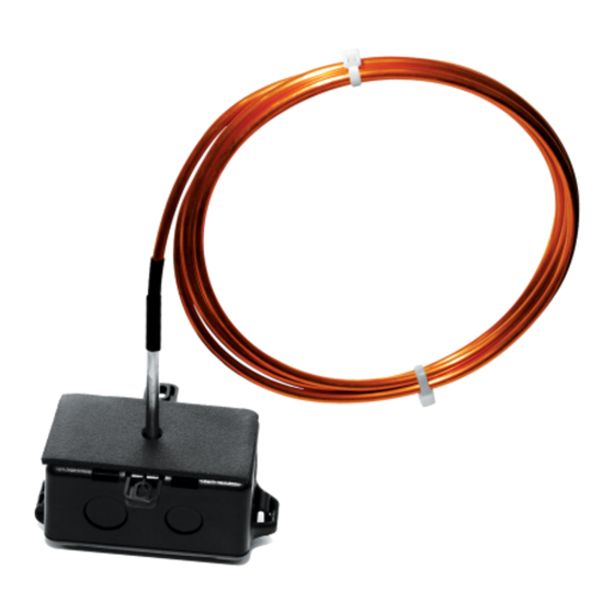
The BACnet MS/TP / Modbus RTU Averaging Series
sensor is designed for use with electronic controllers
in commercial heating and cooling building manage-
ment systems. The ACI BACnet MS/TP / Modbus RTU
Averaging Series sensor monitor the average
temperature in commercial HVAC ductwork and
provides a better average temperature of the air
inside the duct compared to a single point duct
sensor. Averaging sensors are sold in either Copper
or Flexible Averaging variations.
Averaging sensors include a continuous sensing
element, which covers the entire length of the probe.
The Flexible Averaging sensor has either 4 or 9
sensing points depending on the length. It uses
BACnet MS/TP or Modbus for RTU for physical
connection to a BAS or controller, has dip switches to
set addresses and baud rate, parity and stop bits
(Modbus RTU only), and has on board end-of-line
termination. There is no analog output.
WIRING INSTRUCTIONS
The BACnet MS/TP /Modbus RTU Averaging Series
temperature sensor has a depluggable terminal
block located on the front of the PCB. For ease of
wiring, we recommend removing the block, wiring,
and reattaching before mounting. 16 to 22 AWG
two conductor shielded cable is recommended for
powering the sensors.
ACI recommends using Belden 3105 or compatible
cable for RS-485 communication wiring. This wire has
120 ohm input impendence. The terminal blocks
allow for (1) or (2) wires to be connected in each
position for daisy chaining. Daisy chain the RS-485
wiring and do not use "Star" or "T" wiring. Avoid
running communication wires next to AC line
voltage wires. These can be sources of noise that can
a ect signal quality.
Automation Components, Inc.
2305 Pleasant View Road | Middleton, WI 53562
Phone: 1-888-967-5224 | Website: workaci.com
FIGURE 1: ENCLOSURE
DIMENSIONS
The Copper
FIGURE 2: LAYOUT
Page 1
Phone: 1-888-967-5224
Website: workaci.com
3.60"
(91.44 mm)
2.25"
(57.15 mm)
END OF LINE
TERMINATION
TERMINAL
BLOCKS
V
GN
D-
D+
SW4
2
1
BAC
MOD
NET
BUS
RESET
BUTTON
2.35"
(59.80 mm)
LED
EN
DIS
64
32
16
8
4
2
1
4
2
1
Version: 2.0
I0000932
Advertisement
Table of Contents

Subscribe to Our Youtube Channel
Related Manuals for aci BACnet AVERAGING Series


Summary of Contents for aci BACnet AVERAGING Series
- Page 1 (91.44 mm) in commercial heating and cooling building manage- (59.80 mm) ment systems. The ACI BACnet MS/TP / Modbus RTU Averaging Series sensor monitor the average temperature in commercial HVAC ductwork and provides a better average temperature of the air inside the duct compared to a single point duct sensor.
-
Page 2: Mounting Instructions
(6.16 mm) and mounts for mounting. Optional copper capillary (ACI Item #130525) or universal plastic mounting clips (ACI Item #145421) can be ordered. Plastic mounting clips will help insulate the copper sensing element from the metal duct. Ø: 0.21” (5.40 mm) The capillary clips help avoid kinks when bending. - Page 3 BACnet or Modbus RTU protocol selection is done via SW4 switch. Place dipswitch #4 to the OFF position for BACnet and the ON position for Modbus. Refer to FIGURE 6. ACI’s BACnet sensors are master devices. Only master nodes are allowed to send and receive tokens on the MSTP network.
-
Page 4: Baud Rate Selection
INTERFACE (Continued) By default, BACnet Protocol and Auto-Baud is ACI’s Modbus RTU sensors are slave devices. Only factory set. If the sensor is eld adjusted for one master is connected to the bus and several Modbus RTU, the baud rate should be selected at slave nodes are connected to the same trunk. - Page 5 LED INFORMATION TABLE 4: ADDRESS SELECTION One LED indicates four statuses. Solid green shows that power is good, but no data is (64) (32) (16) ADDRESS transmitting. A solid Amber indicates that auto-baud is set and no data has been received to set a baud rate.
- Page 6 Bits needs to be the same as in the Master device Coil 1001 and then read as normal from IR 0003 and con guration. ACI’s Modbus RTU sensors utilize 8 0004. While Coil 1001 is enable, it is possible to data bits during communication exchange.
- Page 7 INPUT REGISTER IR Sensors Present For each bit location: 0 = Sensor not present 1 = Sensor present Bit 0 - Temperature Sensor Bit 1 - RH sensor Reserved Temperature Sensor For example, a value of 312 would represent 31.2 Degrees of the Value units selected in HR1.
-
Page 8: Product Specifications
9001 Thru 9000 Thru Device Name Device Name, Device Location, and Device Description are user 9016 9015 settable character strings (Null terminated) that can be used to allow for system customization and device identi cation. For example: 9017 Thru 9016 Thru Device Location Device Name (Modbus 9001 thru 9016) could be set to a system ID: 9048...
Need help?
Do you have a question about the BACnet AVERAGING Series and is the answer not in the manual?
Questions and answers