Table of Contents
Advertisement
Quick Links
JUMPER SETTINGS - ANALOG
Uses same Version #1 or #2 chips
as Pulse & Floating Point programs
Input
S1
S2
S3
S4
0 - 5 Volts
0 - 10 Volts
0 - 15 Volts
1 - 5 Volts
2 - 10 Volts
3 - 15 Volts
0 - 20 mA
4 - 20 mA
AUTOMATION COMPONENTS, INC
2305 Pleasant View Road
Middleton, Wisconsin 53562 (888) 967-5224
www.workaci.com
Installation and Operation Instructions
Pulse / Analog / Floating Point to Proportional Resistance Output
JUMPER SETTINGS - PULSE & FLOATING POINT
Version #1 - Chip # 0052y0h.hex
Input
S5
S6
S1
S2
0.1 - 25.5
sec. pulse
0.02 - 5
sec. pulse
0.59 - 2.93
sec. pulse
30 sec.
Floating Pt.
60 sec.
Floating Pt.
90 sec.
Floating Pt.
JUMPER SETTINGS - PULSE & FLOATING POINT
Version #2 - Chip # 0054y0b.hex
Input
S3
S4
S5
S6
0.1 - 10
sec. pulse
0.023 - 6
sec. pulse
45 sec.
Floating Pt.
120 sec.
Floating Pt.
240 sec.
Floating Pt.
JUMPER SETTINGS - DUTY CYCLE PULSE
Version #4 - Chip # 0305y1a.hex
Input
0.1 - 10
sec. pulse
Page 1 of 4
DRN3.1
S1
S2
S3
S4
S5
S6
S1
S2
S3
S4
S5
S6
Version : 4.0
I0000475
Advertisement
Table of Contents

Subscribe to Our Youtube Channel
Related Manuals for aci DRN3.1


Summary of Contents for aci DRN3.1
- Page 1 Installation and Operation Instructions DRN3.1 Pulse / Analog / Floating Point to Proportional Resistance Output JUMPER SETTINGS - ANALOG Uses same Version #1 or #2 chips JUMPER SETTINGS - PULSE & FLOATING POINT JUMPER SETTINGS - PULSE & FLOATING POINT as Pulse &...
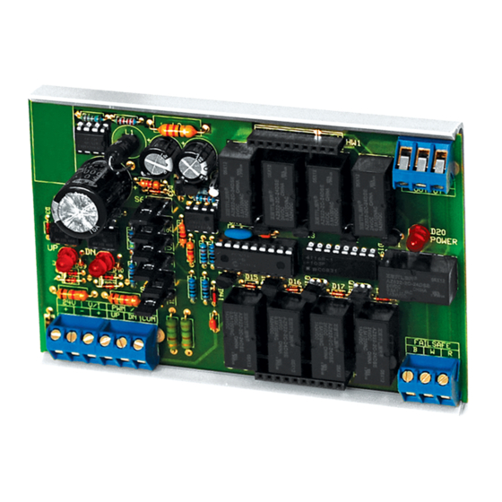
- Page 2 TRIAC SIGNAL INPUT DRN3.1 (Switching Common) 24 VAC Power Supply GND 24V GND 24V OPN CLS AC Power INSTALLATION READ THESE INSTRUCTIONS BEFORE YOU BEGIN INSTALLATION. Ground yourself before touching board. Some components are static sensitive. MOUNTING: Circuit board may be mounted in any position. If circuit board slides out of snap track, a non-conductive “stop” may be required.
- Page 3 DRN3.1) into the DRN3.1. The HW3 pin on the Resistor Network card should be oriented towards the top as shown on Page 1. There are two rows of pins on the RN and two rows of female connections on the DRN3.1.
- Page 4 (this is your jumper wire #2). You are now ready to simulate a timed Up signal. For testing purposes, select the 30 or 45 second range on version 2. Be sure to reset power to allow the DRN3.1 to recognize new settings. Take the free end of jumper wire #2 and connect by holding wire to the Com terminal.
Need help?
Do you have a question about the DRN3.1 and is the answer not in the manual?
Questions and answers