Advertisement
Table of Contents
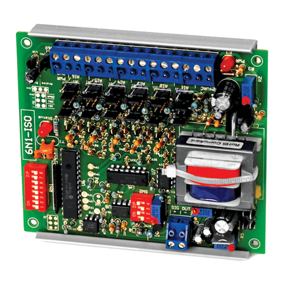
INTERFACE SERIES
Installation & Operation Instructions
6N1-ISO
GENERAL INFORMATION
The 6N1-ISO is a microprocessor controlled
interface designed to provide maximum exibility
with a minimum cost. With a variety of standard
inputs, the 6N1-ISO provides the user with the
ability to interface several devices to a single
analog output. The 6N1-ISO can average two to six
inputs, output the highest of two to six inputs,
output the lowest of two to six inputs, output the
sum of 2 inputs, or output the di erence of two
inputs. Input ranges are jumper selectable and all
modes and analog outputs are DIP switch
selectable. The output signal is optically isolated
from the input signals. The 6N1-ISO also accepts up
to 6 digital inputs (binary sequence) and outputs a
proportional analog signal. The power output
terminal can be used for power if the inputs are
contact closures only.
MOUNTING INSTRUCTIONS
The interface device can be mounted in any
position. If circuit board slides out of snap track, a
non-conductive "stop" may be required. Use only
ngers to remove board from snap track. Slide out
of snap track or push up against side of snap track
and lift that side of the circuit board to remove. Do
not ex board or use tools.
WIRING INSTRUCTIONS
PRECAUTIONS
• 6N1-ISO is powered by 24 VAC only.
• Remove power before wiring. Never connect or disconnect wiring with power applied.
•
When using a shielded cable, ground the shield only at the controller end. Grounding both
ends can cause a ground loop.
•
This device needs to have its own Isolated Transformer. This transformer cannot be
connected/or shared with any other device. It is recommended you use an isolated UL-listed class
2 transformer.
• All wiring must comply with all local and National Electric Codes.
Note: ACI recommends to remove the pluggable terminal blocks to terminate wires rst. The terminal
blocks can be removed using pliers. Once wired, rotate the terminal block 90 Degrees so they are facing
upward, and insert onto pins. This eliminates any wires getting pinched by the snaptrack. See Figure 4
(p.3).
Automation Components, Inc.
2305 Pleasant View Road | Middleton, WI 53562
Phone: 1-888-967-5224 | Website: workaci.com
FIGURE 1: DIMENSIONS
4.00"
(101.6mm)
3.88" (98.55mm)
4.00"
(101.60mm)
Page 1
Phone: 1-888-967-5224
Website: workaci.com
4.60" (116.84mm)
0.70"
(17.78mm)
Version: 8.0
I0000603
Advertisement
Table of Contents

Related Manuals for aci 6N1-ISO


Summary of Contents for aci 6N1-ISO
- Page 1 • All wiring must comply with all local and National Electric Codes. Note: ACI recommends to remove the pluggable terminal blocks to terminate wires rst. The terminal blocks can be removed using pliers. Once wired, rotate the terminal block 90 Degrees so they are facing upward, and insert onto pins.
- Page 2 FIGURE 2: WIRING (-) Output Common (+) Analog Output Status 20mA Analog Digital 24 VAC Power Out (-) Input 6 Common 24 VAC (+) Power Supply Common (-) (+) Input 6 Input 1 (+) (-) Input 5 Common Input 1 Common (-) (+) Input 5 (-) Input 4 Common Input 2 (+)
-
Page 3: Operation
Operation FIGURE 3: TYPICAL BINARY INPUT WIRING The 6N1-ISO can: 1. Read two to six analog inputs and output PWR OUT Choice of 15 VDC the average. or 24 VDC 2. Read two to six analog inputs and output (jumper selectable) the lowest. - Page 4 CALIBRATION, JUMPER & DIP SWITCH SETTINGS The 6N1-ISO output is factory calibrated in all four DIP switch selectable output ranges. Do not adjust the potentiometers on the 6N1-ISO as this may void any warranty. FIGURE 5: INDIVIDUAL INPUT JUMPER SHUNT SETTINGS...
- Page 5 STATUS LED OPERATION Status LED will blink at a very fast rate when 6N1-ISO is rst powered up. After approximately 2 seconds the LED will blink at a rate of approximately twice per second (change of state every 200 ms) indicating microprocessor is functioning properly.
-
Page 6: Product Specifications
-20 to 150°F (-28.9 to 65.5°C) WARRANTY The ACI 6N1-ISO Series is covered by ACI’s Two (2) Year Limited Warranty, which is located in the front of ACI’S SENSORS & TRANSMITTERS CATALOG or can be found on ACI’s website: www.workaci.com. - Page 7 NOTES Page 7 Automation Components, Inc. Version: 8.0 2305 Pleasant View Road | Middleton, WI 53562 I0000603 Phone: 1-888-967-5224 | Website: workaci.com...
- Page 8 Automation Components, Inc. 2305 Pleasant View Road Middleton, WI 53562 Phone: 1-888-967-5224 Website: workaci.com Page 8 Automation Components, Inc. Version: 8.0 2305 Pleasant View Road | Middleton, WI 53562 I0000603 Phone: 1-888-967-5224 | Website: workaci.com...
Need help?
Do you have a question about the 6N1-ISO and is the answer not in the manual?
Questions and answers