
Related Manuals for ETC transtechnik FDX2000


Summary of Contents for ETC transtechnik FDX2000
- Page 1 Operating Manual FDX2000 Software version 4.0.0 Manual version 140217-400 Manual ID number 7260M1201...
-
Page 3: Table Of Contents
Contents This manual ....................1 Meet FDX2000 ....................1 At first glance ................... 1 Simple operation ..................1 FDX2000 − never out-of-date ..............1 Safety ......................1 Notation ....................1 Important rules ..................1 The FDX2000 robust, but..............2 Operating Controls .................. - Page 4 System ....................17 S01, Network protocol ..............17 S02, Logical network................ 17 S03, IP netmask ................17 S04, IP gateway ................18 S05, Dimmer count ................18 S06, DMX input failure ..............18 S07, Global Dimmer feedback ............19 S08, Temperature sensors ...............
-
Page 5: This Manual
This manual As the name suggests, this operating manual is designed to provide the answers to all your questions regarding the operation of the FDX2000 dimmer processor. To make this possible, the manual is structured in the following way: Safety notes Page 1. -
Page 6: The Fdx2000 Robust, But
However, as with all electrical equipment, you will need to observe a few simple rules: • Never switch on equipment that is obviously damaged. Send the equipment to an authorized dealer or back to the factory for repairs. • If there is any reason to suspect a fault, unplug the equipment from the mains supply immediately. -
Page 7: Operating Controls
Operating Controls All inputs are made via 4 buttons and an encoder wheel. Menus and messages are displayed on a backlit, two-line LCD screen. Buttons Allows you to scroll from one menu page to the next. Prerequisite: Edit mode must be inactive. If edit mode is active [PAGE] functions in the same way as [ESC] [PAGE]. - Page 8 LEDs on Front Panel off green green flash orange red flash CPU Processor is Flash- Processor is Software or Hardware functioning programming starting up hardware faulty error correctly DIM Dimmer Dimmer control on control off ...
-
Page 9: Interfaces
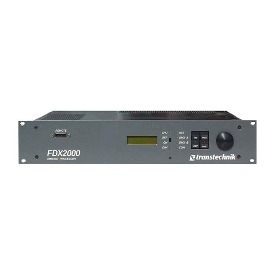
Interfaces Ethernet 100Mb Power supply 3 x 230 V Outputs to DMX A IN/OUT dimmer controller DMX B IN/OUT I/V feedback from Analog control voltage, dimmer units temperature sensors Serial DFB (RS-485) Power to dimmer units Figure 1: Interfaces on the rear of the FDX2000. Figure 2: Front panel of the FDX2000. -
Page 10: Working With Fdx2000
Working with FDX2000 Settings Global settings for the whole cabinet: • Selecting and combining the signal sources • DMX start address or single channel patch • COM-address • Network settings, DMX protocol • Dimmer control on/off • Number of Dimmers within the cabinet •... -
Page 11: Main Menu
Main menu • Appears once the equipment has been started Open • From all other menus: Hit the [ESC] button until the main menu appears Purpose Shows a range of particularly important operating statuses or error messages Status of the DMX inputs A and B A / B DMX input A/B is receiving valid signal No input signal available Status of RS-485 communication... -
Page 12: M01, Dmx Sources
• C error for 2 of 96 dimmers with C monitoring M01, DMX sources It is possible to merge the two input lines, DMX and Ethernet, in any way Input merge you choose. DMX:AB ETH: 5 DMX: Switching in the DMX input No DMX line DMX line A DMX line B... -
Page 13: M05, Dimmer Control On/Off
M05, Dimmer control on/off. Switches the dimmer control on or off. Dimmer control on Options: on, off Factory setting: on The sliding switch on the front panel will also switch the dimmer control on or off. The position of the sliding switch has priority. So, for example, if the sliding switch is set to OFF, dimmer control is deactivated even if on has been selected in the M05 Dimmer control menu M06, Top level menu, dimmer parameters... -
Page 14: Error Messages
Error messages Errors are indicated by appropriate messages. These error messages are shown in the topmost menu level and, in the same way as with all other menu pages, you can scroll through these using the [PAGE] button or the encoder In the event of an error occurring, the appropriate messages will be inserted between the main menu and the Dimmer status menu. -
Page 15: Dimmer Settings
Dimmer settings A range of menus in the second menu level allows you to set the parameters for individual dimmer channels. The initial menu is the M06 Dimmer menu which can be found in the topmost level. The letter D as part of the menu numbering (D01, D02, ...) indicates that this is a dimmer parameter menu. Ranges of Dimmers with identical Settings Dimmers with identical settings are grouped into ranges in the display. -
Page 16: D01, Dimmer Type
D01, Dimmer type. It is possible to set the dimmer type individually for each dimmer Dimmer type 1-96: Dimmer • Hit the [ESC] button until the main menu appears Open • Use [PAGE] or the encoder to scroll to the M06 Dimmer menu •... -
Page 17: D03, Output Voltage At 100% Control Level
The following curves are available: 1=Linear linear to power, corresponds to older transtechnik dimmers with „studio curve“ 2=Stage1 linear to power, with correction for the stage operation 3=Stage2 traditional stage curve 4=Log logarithmic or voltage linear, for 115 V at an output level of 50 % 5=Fluour1 Nesys - fluorescent devices 6=Fluour2... -
Page 18: D06, Switch Point For Dimmer Of Type Nondim
• Use [PAGE] or the encoder to scroll to the D05 Limit menu D06, Switch point for dimmer of type Nondim For all dimmers that are entered as type Nondim you can set individual Switchpoints D06 1-96: 70% upper and lower switching thresholds. Value range:--- (0%) through 100% Activation threshold Factory setting:... -
Page 19: D09, Individual Feedback On/Off
Feedback/Type menu The D08 Feedback/Type menu is only shown when dimmer feedback is activated in S07 menu (page 19). The dimmer feedback can be deactivated: • individually for each dimmer using the D09 Feedback on/off menu (page 15) • or globally for all dimmers using the S07 Dimmer feedback menu (page 19) C and V errors can only be displayed correctly if the associated dimmer is equipped with a current and voltage measurement function. -
Page 20: D11, Dimmer Test
D11, Dimmer test The dimmer processor can locally control the intensity level for each dimmer individually or for ranges of dimmers for testing purposes. In doing this, the values received from external sources, the preset and preheat values are ignored, so that the lamps can always be dimmed to 0%. The initial menu is the D11 Dimmer test menu. -
Page 21: System
System A selection of menus on the second menu level can be used to make parameter settings for the cabinet (for example, behavior of dimmers in the event of failure of control signals, network settings). The initial menu is the M07 System which can be found in the topmost level. The letter S as part of the menu numbering (S01, S02, ...) identifies that this is a system parameter menu. -
Page 22: S04, Ip Gateway
S04, IP gateway The address of the IP gateway is the address of the device which makes gateway S04 it possible to access another network. 192.009.200.254 Factory setting: 192.009.200.254 In case of controlling via sACN you have to enter a really existing gateway or, by default, your own IP address. -
Page 23: S07, Global Dimmer Feedback
S07, Global Dimmer feedback Feedback from the dimmers to the dimmer processor (monitoring of Dimmer current and voltage) can be activated/deactivated for all dimmers feedback: on simultaneously. Options: on, off Factory setting: • Hit the [ESC] button until the main menu appears Open •... -
Page 24: S10, Overtemperature Shutdown
temperature. The shutdown temperature can be set in the S10 Dimmer off menu, see page 20. The S09 Overtemperature warning menu is only displayed if at least one of the temperature sensors is activated in the S08 menu, see page 19. If one of the two sensors is not activated in menu S08 you will not be able to set a warning temperature for that sensor. -
Page 25: Working With Presets
• [EDIT] takes you to the most recently called system menu Sxx • Use [PAGE] or the encoder to scroll to the Reset to factory settings menu • [SAVE] then resets all parameters to the factory settings. • [ESC] exits edit mode, values are not reset List of factory settings see page 31. -
Page 26: P03, Preset Fade Times
• Use [PAGE] or the encoder to scroll to the P02 Preset test menu [EDIT] takes you to the menu where you actually make the settings. Test preset 1 Value range weighting: 0% through 100% Factory setting: Changes/settings take effect immediately. The presets are output parallel to the control level via DMX/Ethernet (HTP merging, Highest Takes Precedence). -
Page 27: P04, Preset Control Via External Signals
Edit modes To allow you to make the various possible settings there are a range of different edit modes which may be called in succession by repeatedly pressing the [EDIT] button (the Edit LED is illuminated). Selecting presets Identified by: Preset number flashes. [ESC] Exits edit mode. -
Page 28: Appendix
Appendix Improvements and New functions Since versions 1.12.1 and 1.18.1 the following improvements and new functions were built into the software: • Timing on DMX-inputs. If breaks within a DMX telegram exceeded a certain limit, the following channels were misinterpreted. This was visible in uncontrolled flickering of lamps. Especially consoles of type Avab Presto faced this problem. -
Page 29: Overview Menus
Overview Menus Top level Displays and Menus Disp Software 3.6.0 Disp device status: DMX inputs active COM port active ETH: DMX from Ethernet active DIM: Dimmer control on/off Disp Dimmer state xx dimmers ready M01: Input merge: DMX A / B Ethernet, universe --, 1 –... -
Page 30: Dimmer Submenu
Dimmer Submenu: M06: Dimmer submenu per dimmer D01: Dimmer type: Dimmer default Nondim switch curve, full input voltage Blind no dimmer special dimmer for HMI devices D02: dimmer curve: 1=linear power linear 2=Stage1 Simulating traditional German analog dimmer 3=Stage2 Simulating traditional German transductor 4=Log Logarithmic/voltage linear 5=Fluour1... -
Page 31: System Submenu
System submenu M07: System submenu S01: Protocol AVAB/UDP UDP & ACN AVAB/IPX UDP & IPX IPX & ACN S02: Logical network 0 .. 9 S03: IP netmask 255.255.255.000 S04: IP gateway 192.9.200.1 S05: Dimmer count 0 – 96 S06: At Timeout blackout buffering preset 1 –... -
Page 32: Technical Data
Technical data Interfaces DMX512/1990 1 x IN / THRU line A 1 x IN / THRU line B Analog control voltages input 12 x, 0 V through +10 V DC / input resistance of approx. 50 kΩ Reference voltage available Digital switch inputs 4 x 0V through +10V DC Input resistance approx. - Page 33 Functions Control capacity 96 dimmer modules Dimmer level output 8/16 Bit Sources of the control signals DMX lines A and B Ethernet, 32 lines 12 analog channels max. 24 stored presets All signals can be switched individually and combined at will (real-time, maximum value derivation) DMX512/1990 address area Start address can be set from 1 through 512 Single channel patch...
- Page 34 Operating Controls • Menu-guided operation using four buttons and encoder Settings wheel for navigation and selection of values, menu-language can be changed • Switch for immediate cutout of control signal to dimmer module Display LCD, 2 line x 16 characters, 61 x 17 mm, backlit Status displays 6 two-color LEDs on the front panel inform about the state of...
-
Page 35: List Of Factory Settings
List of factory settings The dimmer processor can be reset to the factory settings at the touch of a button, see page 20. Parameter Value Source of the dimmer control signals DMX lines A and B Station address IP address 192.009.200.000 DMX start address Dimmer control... -
Page 36: Pin Assignment
Pin assignment Sockets A through H for control of dimmer units Type of sockets A-H: Submit-D, 25 pin. The high-active trigger outputs from two FDX2000 units can be directly switched in parallel when used in redundant installations, they are decoupled using diodes. ZP01 ZP02 ZP03 ZP04 ZP05 ZP06 ZP07 ZP08 ZP09 ZP10 ZP11 ZP12 God Ass. -
Page 37: Remote Socket
Remote socket The Remote socket on the front panel of the FDX2000 (Submin-D, 15 pin) serves to connect an external controller (PC, RS-232). Ass. – – D4– bias D4+ bias RXDPC TXDPC voltage B voltage A Ass. – RTSPC +5 V –... -
Page 38: Feedback Connectors
Feedback connectors These two connectors are used to capture the I/V feedback messages sequentially from the modules. With the help of the actual values all 96 circuits can be managed using time-division multiplex technology. The modules are arranged in groups of 6, each module returns a low-active signal output for current and voltage, in other words, the feedback occurs on a total of 12 lines (U0 through U5 and I0 through I5). -
Page 39: Glossary
Glossary DMX line Separate area for data transfer via DMX. A maximum of 512 parameters can be controlled, to do this 512 addresses can be assigned. Within a line, devices can be assigned at will. Station address Individual network-independent device address for communication via RS-485 or Ethernet Preset Also called a "cue";... - Page 40 Index Front side ......... 5 16 bit control ........16 Glossary ......... 35 Address patch ........ 16 Analog input ........14 Input buffering ........ 18 Input failure ........18 Input voltage ........9 Input voltage, value ......20 Back plane ........5 IP address ........
- Page 41 Presets, test ........21 System ..........9 System .......... 17 Reset..........20 Technical data ....... 28 Temperature sensors ....19 Safety notes ........1 Settings, overview ......6 Single channel patch global .... 8 V error ..........7 Software version ......9 FDX2000 Vers.
Need help?
Do you have a question about the transtechnik FDX2000 and is the answer not in the manual?
Questions and answers