Advertisement
E T C I n s t a l l a t i o n G u i d e
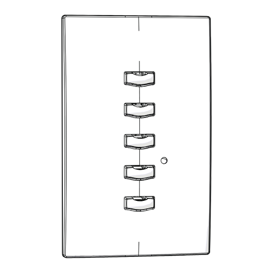
Echo Preset Station Installation
O verv ie w
Echo preset stations are used to activate built-in presets in compatible power
control products.
Stations mount using a standard single-
gang back box (RACO 690 or equivalent),
or an optional surface mount backbox
(ETC part number 7081A2004-1). Station
faceplates and buttons are available in
cream, ivory, grey, black and signal white.
Preset stations are provided with station
electronics, buttons, faceplate, a
termination kit, and installation hardware.
Installation Re quirements
Preset station wiring uses (1) Belden 8471 and (1) 2.5mm
wire. Wiring is topology-free and may be bus, star, loop, home run or any
combination of these. Data wiring is limited to a total of 1640 feet (500 meters)
NEC Class 2 product to be wired in accordance to NEC Article 725 and local
jurisdiction requirements.
N o t e :
Setting Station Functionality
Before installing, you must first assign an
address to the station and, if desired, adjust the
station's functionality. Address is set using the
two numbered wheels on the rear of the station.
Functionality is set using the DIP switches found
just below the numbered wheels. The label on the
rear of the station identifies these components
and functions.
S ett ing the Addre ss and Spac e
Station address is defined by the two numbered
wheels found on the back of the station. The top
address wheel defines the station address (1-16).
Corporate Headquarters
3031 Pleasant View Road, P.O. Box 620979, Middleton, Wisconsin 53562-0979 USA
London, UK
Unit 26-28, Victoria Industrial Estate, Victoria Road, London W3 6UU, UK
Rome, IT
Via Pieve Torina, 48, 00156 Rome, Italy
Holzkirchen, DE
Ohmstrasse 3, 83607 Holzkirchen, Germany
Hong Kong
Rm 1801, 18/F, Tower 1 Phase 1, Enterprise Square, 9 Sheung Yuet Road, Kowloon Bay, Kowloon, Hong Kong
Service: (Americas)
service@etcconnect.com
Web:
www.etcconnect.com
Copyright © 2013 ETC. All Rights Reserved. Product information and specifications subject to change.
7140M2110 Rev A Released 2013-03 ETC intends this document to be provided in its entirety.
E cho Pr e set St a ti on
ETC requires that all stations be grounded by using grounded metal
conduit or a 14 AWG ESD drain wire. All control wiring should be
installed and terminated by a qualified installer and should follow
standard wiring installation practices.
Tel +39 (06) 32 111 683
Tel +49 (80 24) 47 00-0
(UK)
service@etceurope.com
P ag e 1 o f 6
Address wheel
Space wheel
DIP switches
Tel +44 (0)20 8896 1000
Fax +44 (0)20 8752 8486
Fax +49 (80 24) 47 00-3 00
(DE)
techserv-hoki@etcconnect.com
2
(14 AWG) ESD ground
Tel +608 831 4116
Fax +608 836 1736
Fax +44 (0)20 8896 2000
Tel +852 2799 1220
(Asia)
service@etcasia.com
ET C , I nc .
.
Advertisement
Table of Contents

Related Manuals for ETC Echo Control Series


Summary of Contents for ETC Echo Control Series
- Page 1 Copyright © 2013 ETC. All Rights Reserved. Product information and specifications subject to change. 7140M2110 Rev A Released 2013-03 ETC intends this document to be provided in its entirety. E cho Pr e set St a ti on P ag e 1 o f 6 ET C , I nc .
-
Page 2: Setting Station Functionality
Run conduit and wiring as required by the installation drawings. Step 3: Leave a service loop of approximately 10” (254mm) of wiring in the backbox. Ech o Pre se t St at io n Pa ge 2 of 6 ETC, In c. - Page 3 (ground) wire and the green/yellow lead from the pigtail into the terminals. Close the levers onto the wires, securing the connection between the two. Ech o Pre se t St at io n Pa ge 3 of 6 ETC, In c.
-
Page 4: Installing The Station In The Backbox
Overtightening of the mounting screws may result in poor button activation. Step 4: Install the button caps (included with the faceplate kit) so that the clear light tunnels protrude through the caps. Ech o Pre se t St at io n Pa ge 4 of 6 ETC, In c. -
Page 5: Custom Settings
Stations default to controlling presets 1-5. Any station can be set to control any consecutively numbered block of presets. For example: a 5-button station can control presets 1-5, 3-7, 14-18, and so on. Ech o Pre se t St at io n Pa ge 5 of 6 ETC, In c. -
Page 6: Changing Led Color
Se rv ic e If you have any difficulties installing your system or with system startup please contact ETC Technical Services at the office nearest you. ETC contact information is located at the bottom of page 1. Ech o Pre se t St at io n Pa ge 6 of 6 ETC, In c.
Need help?
Do you have a question about the Echo Control Series and is the answer not in the manual?
Questions and answers