
Related Manuals for Mindray WATO EX-65


Summary of Contents for Mindray WATO EX-65
- Page 1 WATO EX-65 Anesthesia Machine Quick Guide Shenzhen Mindray Bio-Medical Electronics Co., Ltd.
- Page 3 The product bears CE mark indicating its conformity with the provisions of the Council Directive 93/42/EEC concerning medical 0123 devices. © Copyright 2008-2009 Shenzhen Mindray Bio-Medical Electronics Co., Ltd. All rights reserved. Contents of this guide are subject to change without prior notice.
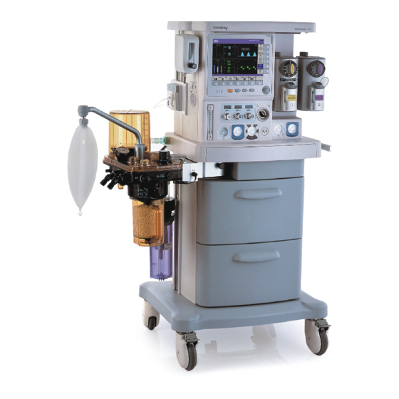
- Page 5 Product Introduction 1.Brake 7.Control knob 12.Cylinder pressure gauge 2.Pipeline pressure gauge 8. Display 13.O2 fl ush button 3.Total fl owmeter 9.Vaporizer 14.Auxiliary electrical outlet 4.Flow control 10.Gas supply connector 15.Drawer lock 5.Electronic fl owmeter 11.System switch 16.Worktable (with drawer) 6.Ventilator control panel...
- Page 6 Product Introduction 1.O2 sensor connector 6.Bellows housing 10.APL (Airway Pressure Limit) valve 2.Inspiration connector 7.Sample gas return port 11.O2 sensor connector 3.Expiration connector 8.Manual bag port 12.Rotary handle 4.Inspiratory check valve 9.Bag/mechanical ventilation switch 13.Sodalime canister 5.Expiratory check valve...
-
Page 7: Product Introduction
Product Introduction 1.Cylinder connector 6.CIS 12 V power supply 9.ACGO (Auxiliary Common connector Gas Outlet) switch 2.Equipotential stud 10.Module slot 7.Speaker 3.Fan 11.AGSS outlet 8.Auxiliary O2 supply 4.Mains inlet 12.AGSS Transfer and 5.Network connector Receiving System... -
Page 8: Control Panel
Control Panel The control panel is located beneath the ventilator display, as shown below: 1. Battery LED 2. AC power LED 3. Operating state LED 4. Alarm silence key To set alarm silence state, push this key to enter 120 s alarm silenced status. -
Page 9: Display Screen
Display Screen This anesthesia machine adopts a high-resolution color TFT LCD to display various parameters, spirometry loops and waveforms (airway pressure, flow, volume, EtCO2, etc). The following is a standard display screen. For descriptions of other screens, refer to Operator's Manual. 1. - Page 10 Display Screen 3. MV&TVe alarm off icon 4. Physiological alarm area 5. Apnea alarm off icon 6. Alarm silence icon area 7. System time 8. Technical alarm area 9. Power supply state icon area Displays power source or battery icon. The icon is displayed when the anesthesia machine is powered by AC power source.
-
Page 11: Inspect The System
Inspect the System Make sure that: The anesthesia machine is undamaged. All components are correctly attached. The breathing system is correctly connected, and the breathing tubes are undamaged. The vaporizers are locked in position and contain suffi cient agent. The gas supplies are connected and the pressures are correct. Cylinder valves are closed on models with cylinder supplies. -
Page 12: Test Intervals
Preoperative Test Test Intervals Perform the preoperative tests listed below at these events: 1.Before each patient. 2.When required after a maintenance or service procedure. The following table indicates when a test must be done. Test Item Test Intervals Pipeline tests Cylinder tests Every day before the fi... -
Page 13: Turn On The System
Turn on the System Connect the power cord to the AC power source.Make sure that the AC power LED is illuminated. Set the system switch to ON.Make sure that both the operating state LED and battery LED are illuminated (the battery is being charged or fully charged). The alarm lamp fl... - Page 14 Mechanical Ventilation Mode Ventilation Mode Make sure that the system is Standby. Set the appropriate Plimit value in the parameter setup shortcut keys area. Check the ACGO switch to make sure that it is OFF . Set the bag/mechanical ventilation switch to the position.
-
Page 15: Turn Off The System
Mechanical Ventilation Mode Stop Mechanical Ventilation Make sure that the APL valve is set properly before stopping mechanical ventilation. The APL valve adjusts the breathing system pressure limit during manual ventilation. Its scale shows approximate pressure. Set the bag/mechanical ventilation switch to the position. -
Page 16: Cleaning And Disinfection
Cleaning and Disinfection WARNING : Obey applicable safety precautions. Read the material safety data sheet for each cleaning agent. Read the operation and service manual for all disinfection equipment. Wear gloves and safety glasses. A damaged O2 sensor can leak and cause burns (contains potassium hydroxide). - Page 17 Cleaning and Disinfection All parts of the breathing system can be cleaned and disinfected. The cleaning and disinfection methods are different for different parts. You need to select the appropriate method to clean and disinfect the parts based on the actual situations to avoid cross-contamination.
- Page 18 Cleaning and Disinfection Clean and Disinfect the Anesthesia Machine Housing Clean the surface of the anesthesia machine housing with a damp cloth soaked in mild detergent (such as 70% ethanol). After cleaning the housing, remove the remaining detergent by wiping with a dry lint free cloth.
-
Page 19: Flow Sensor
Cleaning and Disinfection Breathing Tubes and Y Piece Remove the filter from the Y piece. Disconnect the breathing tubes from the inspiration/expiration connectors on the breathing system. WARNING : When installing the breathing tube, hold the tube connector at both ends of the tube to prevent damage of the tube. -
Page 20: Check Valve Assembly
Cleaning and Disinfection 3.Pull out the fl ow sensors horizontally. Check Valve Assembly 1.Turn the check valve 2.Pull out the check valve. cover counterclockwise to remove it . WARNING : Do not separate the check valve diaphragm from the valve cover. When installing the check valve, depress the valve forcibly to make sure that it is installed in position. - Page 21 Cleaning and Disinfection Sodalime Canister 1.Hold and pull up the rotary handle for 90 degrees. 3.Pull out the sodalime canister from 2.Turn the rotary handle the slot. for 90 degrees counterclockwise. WARNING : Sodalime is a caustic substance and is a strong irritant to eyes, skin and respiratory system.
- Page 22 Cleaning and Disinfection Airway Pressure Gauge Pull off the airway pressure gauge as shown below . Manual Bag Remove the manual bag from the manual bag port on the breathing system as shown below. The anesthesia machine is confi gured The anesthesia machine is not with bag arm: confi...
-
Page 23: Bellows Assembly
Cleaning and Disinfection Bellows Assembly 1.Turn the bellows housing 2.Remove the housing. counterclockwise. 3.Remove the folding bag from the NOTE : bellows base. Before installing the bellows housing, check that the sealing component on the breathing system is in position. If not, you must install the sealing component properly before installing the bellows housing. -
Page 24: Breathing System
Cleaning and Disinfection Breathing system 1.Remove the breathing system assembly 2.Remove the breathing system from according to the aforementioned the breathing system adapter with both procedures.Hold the breathing system hands. with one hand. Pull up the locking catches on the breathing system adapter with the other hand to unlock it. -
Page 25: Maintenance
Maintenance Do not use malfunctioning anesthesia machine. Have all repairs and service done by an authorized service representative. Replacement and maintenance of tube parts listed in this manual may be undertaken by a competent, trained individual having experience in the repair of devices of this nature. After repair, test the anesthesia machine to ensure that it is functioning properly, in accordance with the specifi... -
Page 26: Maintenance Schedule
Maintenance NOTE : These schedules are the minimum frequency based on typical usage of 2000 hours per year. You should service the equipment more frequently if you use it more than the typical yearly usage. Maintenance Schedule: Minimum Maintenance frequency Clean the external surfaces. -
Page 27: Flow Sensor Calibration
Flow Sensor Calibration NOTE : Do not perform calibration while the unit is connected to a patient. During calibration, do not operate the pneumatic parts. Do not move or press the breathing tubes especially. During calibration, the drive gas pressure must be kept above 0.3 MPa. Otherwise calibration failure may result. - Page 28 Flow Sensor Calibration In case of fl ow sensor calibration failure, refer to the following table for troubleshooting. Failure description Possible cause Recommended action 1. Check the supply pressure and ensure that it is not lower than 0.2 MPa. 1. The pipeline supply 2.
- Page 29 Commonly-encountered Problems Failure description Possible cause Recommended action In case of this problem, judge the actual gas delivery volume to the patient by observing the graduation on the bellows housing. If it is abnormal, apply manual ventilation. After the operation, take the measures below to remove the problem.
- Page 30 Commonly-encountered Problems Failure Possible cause Recommended action description 1 Check if the breathing tubes 1 The breathing tubes are are pressed or bent. Check if the occluded. fi lter connected to the Y-piece is fi lled with patient secretions and 2 Patient airway is occluded.
- Page 31 Commonly-encountered Problems Failure Possible cause Recommended action description 1. TV is set too high. Rate 1 Decrease TV or the respective or I:E setting is too high, settings for Rate and I:E to which disables complete lengthen expiratory duration. expiration and results in 2.
- Page 32 Commonly-encountered Problems Failure Possible cause Recommended action description 1.Check if the patient is in good condition. According to patient physiological status, increase TV delivery or fresh gas fl ow, or 1 Patient spontaneous check if patient tracheal intubation breathing is so strong that The alarm [Paw is in good condition.
- Page 33 Commonly-encountered Problems Failure Possible cause Recommended action description 1. Switch on TV compensation. 2. Decrease the fresh gas fl ow appropriately. 3. Check the breathing system and patient tracheal intubation for leakage. 4. During ventilation, observe the 1. TV compensation is graduation on the bellows housing switched off.
- Page 34 Commonly-encountered Problems Failure Possible cause Recommended action description 1 The ventilator fails to 1. Check if the breathing system is detect changes of fl ow installed properly or leaks signifi cantly. and presssure. Check if the fl ow sensor is in good 2 If the backup condition or installed properly.
- Page 35 Commonly-encountered Problems Failure Possible cause Recommended action description 1. Connect the O2 sensor. If it is not confi gured, select [User Maintenance >>] → [Set O2 Sensor Monitoring >>]. Then select [OFF] from the pop-up The alarm 1. The O2 sensor is not menu.
- Page 36 Commonly-encountered Problems Failure Possible cause Recommended action description 1. Loose connections 1. Check for loose connections between the breathing between the breathing tubes and the tubes and the connectors. If the disposable tubes connectors occur. are used, replace them timely. During Patient tracheal an operation, check patient tracheal intubation leaks.
- Page 37 Commonly-encountered Problems Failure Possible cause Recommended action description 1. Switch on the ACGO. 2. TV or pressure level is set too low, which causes In mechanical 1. Switch off the ACGO. low gas delivery fl ow. TV ventilation mode, 2. Decrease the fresh gas and setting is not high but the the folding bag increase the TV appropriately to...
- Page 40 Shenzhen Mindray Bio-Medical Electronics Co., Ltd. Mindray Building, Keji 12th Road South, Hi-tech Industrial Park, Nanshan, Shenzhen 518057 P.R. China Tel: +86 755 26582888 Fax: +86 755 26582680...
Need help?
Do you have a question about the WATO EX-65 and is the answer not in the manual?
Questions and answers