Sign In
Upload
Manuals
Brands
Mindray Manuals
Medical Equipment
WATO EX-65
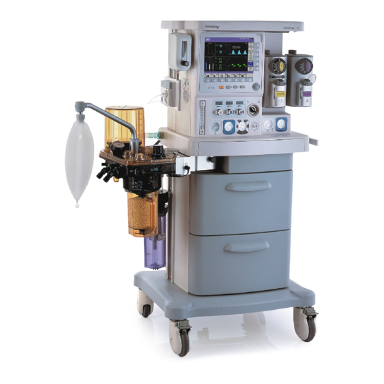
Mindray WATO EX-65 Anesthesia Machine Manuals
Manuals and User Guides for Mindray WATO EX-65 Anesthesia Machine. We have
3
Mindray WATO EX-65 Anesthesia Machine manuals available for free PDF download: Service Manual, Operator's Manual, Quick Manual
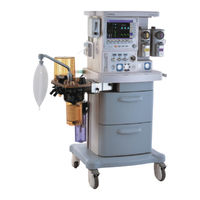
Mindray WATO EX-65 Operator's Manual (277 pages)
Anesthesia Machine
Brand:
Mindray
| Category:
Medical Equipment
| Size: 17 MB
Table of Contents
Table of Contents
9
Safety Information
17
Dangers
18
Warnings
18
Cautions
19
Notes
20
Equipment Symbols
21
2 The Basics
23
System Description
23
Intended Use
23
Contraindications
23
Components
24
Equipment Appearance
25
Front View
25
Display and Control Panel
25
Vaporizer
26
Gas Supply Connector
26
System Switch
26
Cylinder Pressure Gauge
26
Breathing System
27
Bag/Mechanical Ventilation Switch
28
APL (Airway Pressure Limit) Valve
28
Sodalime Canister
28
Rear View
29
Power Supply
29
Module Slot
30
ACGO (Auxiliary Common Gas Outlet) Switch
30
Anesthesia Information System (CIS)
31
Batteries
34
3 System Controls and Basic Settings
35
Display Control
35
Alarm Lamp
35
Control Knob
35
MV&Tve Alarm Key
36
Normal Screen Key
36
Standby Key
36
Alarm Silence Key
36
Display Screen
37
Ventilation Mode Prompt Area
37
Lung Icon Area
37
MV&Tve Alarm off Icon
37
Physiological Alarm Area
38
Apnea Alarm off Icon Area
38
Alarm Silence Icon Area
38
System Time Area
38
Basic Settings
39
Adjust Screen Brightness
39
Adjust Sound Volume
39
Key Sound Volume
39
Set System Time
40
Set Language
40
Set Unit
40
Restore Default Configurations
40
Set the IP Address of Anesthesia Information System (CIS)
41
Restore the Factory Default Configuration of the bis Module
41
4 Operations and Ventilation Setup
43
Turn on the System
43
Turn off the System
43
Input Fresh Gas
44
2, N 2 O and Air Inputs
44
Set Anesthetic Agent
45
Select the Desired Anesthetic Agent
45
Adjust the Concentration of Anesthetic Agent
45
Set Manual Ventilation Mode
46
Make Settings before Starting Mechanical Ventilation Mode
47
Volume Control Ventilation (VCV)
47
Description
47
Waveforms
48
Start VCV Mode
48
Parameter Setup Shortcut Keys Area in VCV Mode
49
Set Parameters in VCV Mode
49
Parameter Range and Default Value in VCV Mode
50
Pressure Control Ventilation (PCV)
50
Start PCV Mode
51
Parameter Setup Shortcut Keys Area in PCV Mode
52
Set Parameters in PCV Mode
52
Synchronized Intermittent Mandatory Ventilation (SIMV)
53
Parameter Range and Default Value in PCV Mode
53
Simv-VC
53
Simv-Pc
53
Start SIMV Mode
55
Parameter Setup Shortcut Keys Area in SIMV Mod
56
Set Parameters in SIMV Mode
57
Trigger Level
58
PSV Insp Termination Level]
58
Parameter Range and Default Value in SIMV Mode
59
Pressure Support Ventilation (PSV)
59
Start PSV Mode
60
Parameter Setup Shortcut Keys Area in PSV Mode
61
Set Parameters in PSV Mode
61
Backup Mode Active
62
Parameter Range and Default Value in PSV Mode
63
Start Mechanical Ventilation
63
Set the Timer
64
Start the Timer
64
Stop the Timer
64
Reset the Timer
64
Stop Mechanical Ventilation
65
5 User Interface and Parameter Monitoring
67
Screen Layout
67
Standby Screen
68
Normal Screen
69
Parameter&Graph Area
69
Waveform Area
69
Special Screen
70
Big Numerics/Measured Values Sharing Area
70
Screen Setup
71
Parameter Monitoring
71
O2 Concentration Monitoring
71
Set Fio2 Alarm Limits
72
Display Fio2
72
Anesthetic Agent (AA) Concentration Monitoring
73
Display O2 Waveform
73
Display AG Parameters
73
CO2 Concentration Monitoring
74
Display CO2 Parameters
74
Display CO2 Waveform
74
Pressure Monitoring
75
Other Settings
75
Display Pressure Parameters
75
Display Paw Waveform
75
Set Paw Unit
76
Review Ppeak Trend
76
Tidal Volume Monitoring
76
Display Tidal Volume and Breath Rate Parameters
76
Display Flow Waveform
77
Set Flow Waveform
77
Tidal Volume Compensation
78
Set MV and Tve Alarm Limits
78
Review Tve and MV Trends
78
Volume Monitoring
79
Display Volume Waveform
79
Set Volume Waveform
79
Breath Rate Monitoring
79
BIS Monitoring
80
Display bis Parameters
80
Display bis EEG Waveform
81
Set bis EEG Waveform
81
Display Electronic Flowmeter
82
Spirometry Loop
82
Preoperative Test Schedules
83
Test Intervals
83
Inspect the System
84
Power Failure Alarm Test
84
O2 Pipeline Test
85
N2O Pipeline Test
86
Air Pipeline Test
86
Cylinder Tests
86
Check the Cylinder in Full Status
86
O2 Cylinder High Pressure Leak Test
87
N2O Cylinder High Pressure Leak Test
87
Flow Control System Tests
87
Without O2 Sensor
87
With O2 Sensor
89
Vaporizer Back Pressure Test
90
Breathing System Tests
91
Bellows Test
91
Breathing System Leak Test in Mechanical Ventilation Status
92
Breathing System Leak Test in Manual Ventilation Status
93
APL Valve Test
93
Alarm Tests
94
Prepare for Alarm Tests
94
Test the O2 Concentration Monitoring and Alarms
95
Test the Low Minute Volume Alarm
95
Test the Apnea Alarm
96
Test the Sustained Airway Pressure Alarm
96
Test the High Paw Alarm
96
Test the Low Paw Alarm
97
Test the AG Module Alarm
97
Preoperative Preparations
97
Inspect the AGSS
98
7 User Maintenance
99
Repair Policy
99
Maintenance Schedule
100
Breathing System Maintenance
101
Flow Sensor Calibration
101
O2 Sensor Calibration
103
21% O2 Calibration
103
100% O2 Calibration
104
Water Build-Up in the Flow Sensor
105
Prevent Water Build-Up
105
Clear Water Build-Up
106
Airway Pressure Gauge Zeroing
106
AGSS Transfer Tube Maintenance
108
8 CO2 Monitoring
109
Introduction
109
Identify CO2 Module
110
Use a Sidestream CO2 Module
111
Prepare to Measure CO2
111
Make CO2 Settings
112
Set Pump Rate
112
Set Working Mode
112
Set Gas Compensations
113
Set Humidity Compensation
113
Restore Defaults
113
Set CO2 Waveform
114
Measurement Limitations
114
Troubleshooting
114
Scavenge the Sample Gas
115
Zero the Sensor
115
Calibrate the Sensor
115
Use a Microstream CO2 Module
116
Set Maximum Hold
118
Set Automatic Standby Time
118
Use a Mainstream CO2 Module
121
Understand MAC Values
126
Identify AG Modules
127
Prepare to Measure AG
127
Make AG Settings
129
Set O2 Compensation
129
Set CO2 Unit
130
Change Anesthetic Agent
130
Measurement Limitations
131
Troubleshooting
131
Calibrate the AG Module
132
Scavenge the Sample Gas
132
Identify the bis Module
133
Understand bis Parameters
135
Non-Extend Sensor
135
Extend Sensor
135
Prepare to Measure bis
136
Continuous Impedance Check
137
Cyclic Impedance Check
138
BIS Sensor Check Window
138
Set bis Smoothing Rate
139
Set bis Related Waveforms
140
To Set bis EEG Waveform
140
To Set bis Trend Waveform
140
Alarms
141
Alarm Categories
141
Physiological Alarms
141
Technical Alarms
141
Alarm Levels
142
Alarm Indicators
142
Audible Alarm Tones
143
Alarm Message
143
Flashing Alarm Numeric
143
Alarm Status Symbols
143
Set Alarm Volume
144
Set Alarm Limits
144
Set Ventilator Alarm Limits
144
Set CO2 Alarm Limits
144
Set AG Alarm Limits
145
Set bis Alarm Limits
145
Set Alarm Level
145
Set Cardiopulmonary Bypass (CPB) Alarm
145
Set MV&Tve Alarm
146
Set Apnea Alarm
146
In Non-Mechanical Ventilation Mode
146
Alarm Silence
147
Set 120 S Alarm Silence
147
Cancel 120 S Alarm Silence
147
When an Alarm Occurs
147
Trend and Logbook
149
Trend Graph
149
Trend Table
150
Alarm Logbook
151
Installations and Connections
153
Install the Breathing System
153
Breathing System Diagrams
154
Circuit Adapter Diagram
155
Install the Bag Arm
158
Install the Bellows
159
Install the Flow Sensor
161
Install the O2 Sensor
162
Install the Sodalime Canister
164
Assemble the Sodalime Canister
166
Change the Sodalime
169
Install the Breathing Tubes
171
Install the Manual Bag
172
Install the Vaporizer
173
Assemble the Vaporizer
173
Fill the Vaporizer
177
Pour Fill System
177
Quik-Fil System
178
Drain the Vaporizer
179
Install/Replace the Gas Cylinder
181
Install Modules
183
Install the CO2 Module
183
Install the AG Module
183
Install the bis Module
184
Pneumatic Connectors
184
Connect the Pipeline Gas Supplies
185
Install the Gas Cylinder
186
CIS Connector
186
Scavenging
186
AGSS Transfer and Receiving System
187
Assemble the AGSS
188
Waste Gas Disposal System
189
Cleaning and Disinfection
191
Clean and Disinfect the Anesthesia Machine
192
Disassemble the Breathing System Cleanable
192
O2 Sensor
193
Manual Bag
194
Breathing Tubes
195
Airway Pressure Gauge
196
Bag Arm
196
Bellows Assembly
197
Flow Sensor
198
Expiratory Check Valve Assembly
199
Inspiratory Check Valve Assembly
199
Water Collection Cup
201
Breathing Mask
208
Inspiratory and Expiratory Check Valves Assembly
208
Breathing Tubes and y Piece
210
Accessories
213
Theory of Operation
217
Pneumatic Circuit System
217
Pneumatic Circuit Diagram
217
Parts List
218
Gas Supplies
219
Fresh Gas
219
Anesthetic Ventilator
219
Electrical System Structure
220
Electrical Block Diagram
220
Product Specifications
223
Safety Specifications
223
Environmental Specifications
224
Power Requirements
224
External AC Power Supply
224
Auxiliary Output Supply (with Isolation Transformer)
224
Physical Specifications
225
Internal Battery
225
Main Unit
225
Top Shelf
225
Pneumatic Circuit System Specifications
226
LED Indication
226
Audio Indication
226
Breathing System Specifications
227
Flowmeter
227
O2-N2O Link System
227
System Leakage and System Compliance
227
Interface and Connector
228
Expiratory Resistance
229
Inspiratory Resistance
229
Ventilator Parameter Setting Range
229
PEEP Setting Range
230
Ventilator Performance
230
Ventilator Monitored Parameters
230
PEEP Monitored Parameter
230
Ventilator Accuracy
231
Control and Monitoring Accuracy
231
Alarm Settings
231
Anesthetic Vaporizer
232
O2 Sensor Specifications
233
Signal Stability
234
Humidity Effects
235
Pressure Effects
235
Temperature Dependence
235
CO2 Module Specifications
236
Mainstream CO2 Module Specifications
236
Microstream CO2 Module Specifications
236
Sidestream CO2 Module Specifications
237
Effect of Interfering Gas on CO2 Measured Value
238
AG Module Specifications
239
Effect of Interfering Gas on AG Measured Value
242
BIS Module Specifications
243
BIS Module
243
Emc
245
Guidance and Declaration - Electromagnetic Emissions
246
Guidance and Declaration - Electromagnetic Immunity
246
Alarm Messages
251
Physiological Alarm Messages
251
Technical Alarm Messages
254
Symbols and Abbreviations
265
Factory Defaults
269
CO2 Module
269
Mainstream CO2 Module
269
Microstream CO2 Module
269
Advertisement
Mindray WATO EX-65 Service Manual (322 pages)
Anesthesia Machine
Brand:
Mindray
| Category:
Medical Equipment
| Size: 36 MB
Table of Contents
Table of Contents
7
1 Safety
13
Safety Information
13
Dangers
14
Warnings
14
Cautions
14
Notes
15
Equipment Symbols
15
2 Theory of Operation
17
Pressure Unit Conversion Table
17
Gas Flow
18
Pneumatic Circuit Diagram
18
Parts List
19
Key to Symbols
20
Description
20
3 Checkout and Test
37
System Inspection
37
Pipeline Tests
38
Cylinder Tests
38
Check the Cylinders Are Full
39
Cylinder High Pressure Leak Test
39
Flow Control System Tests
39
Without O2 Sensor
39
With O2 Sensor
41
Vaporizer Back Pressure Test
41
O2 Flush Test
42
In Mechanical Ventilation Mode
42
In Manual Ventilation Mode
43
Breathing Circuit Tests
43
Bellows Test
44
Breathing System Leak Test in Mechanical Ventilation Mode
46
Breathing System Leak Test in Manual Ventilation Mode
48
APL Valve Test
49
Pressure Relief Valve Test
50
Alarm Tests
51
Prepare for Alarm Tests
51
Test the O Concentration Monitoring and Alarms
52
Test the Low Minute Volume (MV) Alarm
52
Test the Apnea Alarm
53
Test the Sustained Airway Pressure Alarm
53
Test the High Paw Alarm
53
Test the Low Paw Alarm
54
AGSS Inspection
54
Check the Float
54
Check the Transfer Tube and Active Scavenging Tube
55
Power Failure Test
56
Electrical Safety Tests
57
4 Maintenance and Calibration
59
Equipment Maintenance
59
One-Year Replaceable Parts
59
Three-Year Replaceable Parts
67
System Test
67
Check the Mechanical Ventilation Mode
68
Breathing System Leak Test in Mechanical Ventilation Mode
71
Breathing System Leak Test in Manual Ventilation Mode
71
Check the Sensor Zero Point
71
Check the Flow Sensor Accuracy
72
Check the Pressure Sensor Accuracy
73
Check the Electronic Flowmeter Accuracy
74
System Calibration
76
Flow Calibration (User)
78
Flow Calibration (Factory)
79
Pressure Calibration (Factory)
85
Electronic Flowmeter Calibration (Factory)
89
Pressure and Flow Zeroing (Factory)
92
Electronic Flowmeter Zeroing (Factory)
93
O2 Sensor Calibration (Optional)
94
CO2 Calibration (Factory)
95
AG Calibration (Factory)
97
O2 Module Calibration (Factory)
99
Software Upgrade
101
Software Function Activation
108
Change the Software Configuration of Electronic Flowmeters
111
Load Gas Module or bis Module
114
Load O2 Sensor Monitoring Function
115
Select the Drive Gas
116
Zero the Airway Pressure Gauge
117
Adjust the APL Valve Accuracy
118
5 Troubleshooting
121
Introduction
121
Technical Alarm Check
121
Ventilator Related Alarms
121
Electronic Flowmeter Related Alarms
129
Pneumatic Circuit System Problems
131
Tools for On-Site Maintenance
131
Gas Supplies and Drive Gas
140
Anesthetic Gas Delivery System
148
Patient Circuit
162
Tidal Volume
177
Preparations before Using the Valves-Test Tool
179
Tool Screen and the Components
180
Description
181
Hardware and Electrical Problems
186
6 Repair and Disassembly
189
Prepare for Disassembly
190
Tools
190
Preparations
190
Bleed Gas Pressure
191
Disassemble the Assemblies
191
Remove the Top Panel
191
Remove the Rear Panel
192
Remove the Trolly Rear Panel Assembly
193
Replace the System Switch
193
Remove the Left Front Panel Assembly
195
Remove the Throttling Device
196
Disassemble the Display Assembly
197
Remove the Flowmeter Control Board
198
Remove the Total Flowmeter
198
Disassemble the Gas Supply Inlet Assembly
199
Remove the ACGO Switch Assembly
201
Remove the O2 Flush Button Assembly
202
Remove the Vaporizer Manifold Assembly
203
Disassemble the Pipeline Pressure Gauges
205
Disassemble the Expiratory Valve Assembly
206
Remove the Three-Way Valve
208
Remove the Auxiliary O2 Supply Assembly
208
Remove the AGSS Assembly
209
Remove the Main Control Board
211
Remove the Button Board
211
Remove the Monitor Board
212
Remove the Speaker
213
Remove the Power Box
213
Replace the Fuse
216
Replace the Built-In Battery
217
Remove the Power Cord
218
Remove the Isolation Transformer
218
Replace the Caster
220
Replace the Drawer
221
Disassemble the Breathing System
222
Remove the O2 Sensor
222
Remove the Breathing Tubes
223
Remove the Flow Sensor
224
Remove the Manual Bag
225
Disassemble the Bellows Assembly
226
Disassemble the Pop-Off Valve Assembly
227
Disassemble the Expiratory Check Valve Assembly
228
Disassemble the Inspiratory Check Valve Assembly
228
Remove the Sodalime Canister
229
Remove the Water Collection Cup
230
Remove the Airway Pressure Gauge
231
Remove the Bag Arm
231
Remove the Circuit
232
Remove the Sodalime Canister Connection Block Assembly
233
Remove the Upper Cover Assembly
237
Remove the Median Plate Assembly
237
Remove the Lower Cover Assembly
238
Remove the APL Valve Assembly
241
Electrical and Pneumatic Connections
241
Electrical Connections
242
Pneumatic Connections
246
Connections between Pneumatic Circuit, Breathing System and Monitor Board
258
7 Parts
261
Main Unit
261
7.1.1.2 Parts List
262
S/N P/N
264
Top Panel Assembly
264
Left Front Panel Assembly
265
Left Front Panel Assembly (10"Display)
265
Pipeline Pressure Gauge Assembly
266
Bolt
267
Cross Recessed Small Pan Head Screw Assembly GB/T9074.8
267
Display Assembly
267
M04-051140
267
M3X8 Rustproof Nickel Plating
267
Nickel Plating
267
Single Coil Spring Lock Washer, Normal Type GB/T93-1987 3
267
Rustproof Nickel Plating
267
Cross Recessed Small Pan Head Screw Assembly GB/T9074.8
268
M04-051139
268
Trolly Assembly (with Auxiliary Electrical Outlet/Euro Standard/220V)
268
M04-000205
269
Trolly Drawer Assembly
270
Trolly Rear Panel Assembly
271
Modular Rack Assembly
272
Ground Plate Assembly of Modular Rack
273
Circuit Bracket Assembly
274
Tabletop Assembly
275
Tabletop Operation Console Assembly
277
Isolation Transformer Mounting Assembly
279
Auxiliary Electrical Outlet Assembly (220V)
280
Power Box Assembly
281
Rear Plate Assembly
283
CIS Assembly
284
O2, N2O and AIR Supplies Inlet Assemblies
286
Auxiliary O2 Supply Assembly
287
O2+AIR System Switch
288
O2 Flush Button Assembly
289
ACGO Assembly
290
Gas Reservoir Assembly
291
Expiratory Valve Assembly
292
Throttling Device (O2+N2O+AIR)
294
O2 Cylinder Bracket Assembly
295
N2O Cylinder Bracket Assembly
296
Double-Vaporizer Manifold Assembly
297
Single-Vaporizer Manifold Assembly
299
AGSS Assembly
300
Stainless Steel Cross Recessed Countersunk Head Screw
269
Breathing Circuit
302
Lifting Device Assembly
302
Sodalime Canister Assembly
304
Canister Connection Block Assembly
305
BYPASS Upper Cover Assembly
306
Bag Arm Assembly
307
Upper Cover Assembly
308
APL Valve Assembly
309
Bag/Mechanical Ventilation Switch Assembly
311
Median Plate Assembly
312
Lower Cover Assembly
314
Expiratory Flow Sensor Assembly
315
Inspiratory Flow Sensor Assembly
316
Upper Cover 2 Assembly
317
Folding Bag Assembly
318
Lower Cover 2 Assembly
319
Airway Pressure Gauge Assembly
320
Mindray WATO EX-65 Quick Manual (41 pages)
Anesthesia Machine
Brand:
Mindray
| Category:
Medical Equipment
| Size: 1 MB
Table of Contents
Product Introduction
7
Control Panel
8
Display Screen
9
Inspect the System
11
Test Intervals
12
Turn on the System
13
Input Fresh Gas
13
Turn off the System
15
Cleaning and Disinfection
16
Flow Sensor
19
Check Valve Assembly
20
Water Collection Cup
20
Bellows Assembly
23
Breathing System
24
Maintenance
25
Maintenance Schedule
26
Flow Sensor Calibration
27
Advertisement
Advertisement
Related Products
Mindray WATO EX-55
Mindray WATO EX-55Pro
Mindray WATO EX-65Pro
Mindray SynoVent E5
Mindray ePM 10MA
Mindray ePM 10MC
Mindray ePM 12MA
Mindray ePM 12MC
Mindray Eagus I9
Mindray Eagus I8 Easi
Mindray Categories
Medical Equipment
Diagnostic Equipment
Measuring Instruments
Monitor
Water Pump
More Mindray Manuals
Login
Sign In
OR
Sign in with Facebook
Sign in with Google
Upload manual
Upload from disk
Upload from URL