Table of Contents
Advertisement
Quick Links
Advertisement
Chapters
Table of Contents

Related Manuals for Mindray WATO EX-55


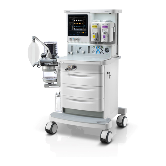
Summary of Contents for Mindray WATO EX-55
- Page 1 WATO EX-55/65 Anesthesia Machine Service Manual...
- Page 3 Mindray, nor the rights of others. Mindray does not assume any liability arising out of any infringements of patents or other rights of third parties.
- Page 4 FOR YOUR NOTES...
- Page 5 Preface Manual Purpose This manual provides detailed information about the assembling, dissembling, testing and troubleshooting of the equipment to support effective troubleshooting and repair. It is not intended to be a comprehensive, in-depth explanation of the product architecture or technical implementation.
- Page 6 FOR YOUR NOTES...
-
Page 7: Table Of Contents
Contents 1 Safety ..........................1-1 1.1 Safety Information ......................1-1 1.1.1 Dangers ......................1-2 1.1.2 Warnings......................1-2 1.1.3 Cautions ......................1-2 1.1.4 Notes ........................1-3 1.2 Equipment Symbols ......................1-3 2 Theory of Operation ......................2-1 2.1 Pressure Unit Conversion Table ..................2-1 2.2 Gas Flow ......................... - Page 8 3.9.4 Test the Apnea Alarm ..................3-17 3.9.5 Test the Sustained Airway Pressure Alarm............3-17 3.9.6 Test the High Paw Alarm.................. 3-17 3.9.7 Test the Low Paw Alarm .................. 3-18 3.10 AGSS Inspection ......................3-18 3.10.1 Check the Float ....................3-18 3.10.2 Check the Transfer Tube and Active Scavenging Tube........
- Page 9 5.1 Introduction........................5-1 5.2 Technical Alarm Check ....................5-1 5.2.1 Ventilator Related Alarms .................. 5-1 5.2.2 Electronic Flowmeter Related Alarms ............... 5-9 5.3 Pneumatic Circuit System Problems ................5-11 5.3.1 Tools for on-site Maintenance ................5-11 5.3.2 Gas Supplies and Drive Gas................5-20 5.3.3 Anesthetic Gas Delivery System ..............
- Page 10 6.2.22 Remove the Speaker..................6-25 6.2.23 Remove the Power Box.................. 6-25 6.2.24 Replace the Power Board ................6-27 6.2.25 Replace the Fuse .................... 6-28 6.2.26 Replace the Built-in Battery................6-29 6.2.27 Remove the Power Cord ................6-30 6.2.28 Remove the Isolation Transformer ..............6-30 6.2.29 Replace the Caster..................
- Page 11 7.1.7 Trolly Rear Panel Assembly................7-11 7.1.8 Modular Rack Assembly .................. 7-12 7.1.9 Ground Plate Assembly of Modular Rack............7-13 7.1.10 Circuit Bracket Assembly................7-14 7.1.11 Tabletop Assembly ..................7-15 7.1.12 Tabletop Operation Console Assembly ............7-17 7.1.13 Isolation Transformer Mounting Assembly............ 7-19 7.1.14 Auxiliary Electrical Outlet Assembly (220V) ..........
- Page 12 FOR YOUR NOTES...
-
Page 13: Safety
Safety 1.1 Safety Information DANGER Indicates an imminent hazard that, if not avoided, will result in death or serious injury. WARNING Indicates a potential hazard or unsafe practice that, if not avoided, could result in death or serious injury. CAUTION Indicates a potential hazard or unsafe practice that, if not avoided, could result in minor personal injury or product/property damage. -
Page 14: Dangers
There is high voltage inside the equipment. Never disassemble the equipment before it is disconnected from the AC power source. This equipment can be disassembled by Mindray trained and authorized personnel only. Be sure of static discharge before disassembling the equipment. Wear antistatic wrist straps or gloves when disassembling the parts labelled with static-sensitive symbolsto avoid damage to the parts. -
Page 15: Notes
1.1.4 Notes NOTE Refer to Operator’s Manual for detailed operation and other information. 1.2 Equipment Symbols Attention: Consult accompanying documents Dangerous voltage (this manual) Alternating current Fuse Battery Equipotential Operating state Autoclavable Material description Not autoclavable Power On Power Off Reset Standby Alarm silence key... - Page 16 USB connector sensor connector Air supply connector O supply connector Sample gas return port (to Upward (Pop-off valve) the AGSS) VGA connector supply connector Table top light AGSS outlet Cylinder PEEP outlet Isolation transformer Vaporizer APL valve CIS connector Maximum level of the CAUTION HOT sodalime canister Lock or unlock as the arrow...
-
Page 17: Theory Of Operation
Theory of Operation 2.1 Pressure Unit Conversion Table mmHg mbar 7.5X10 9.8X10 1.02X10 1X10 1X10 1.45X10 1X10 1X10 1X10 0.75 9.8X10 1.02 1X10 1.45X10 1X10 1X10 9.8X10 10.2 1X10 0.145 1X10 1X10 1X10 7.5X10 1.02X10 1X10 1.33X10 1.33 0.133 1.33X10 1.32X10 1.36 1.33... -
Page 18: Gas Flow
2.2 Gas Flow 2.2.1 Pneumatic Circuit Diagram... -
Page 19: Parts List
2.2.2 Parts List O2 P-Line Float flowmeter O2 cylinder Double-vaporizer manifold Air P-Line Check valve N2O P-Line Pressure relief valve (38 kPa) N2O cylinder ACGO selector switch Regulator (0.4 MPa) Inspiratory valve Safety valve (0.7 MPa) Sodalime canister Filter BYPASS valve Regulator (0.2 MPa) Expiratory valve 10 Inlet gas flow regulator... -
Page 20: Key To Symbols
2.2.3 Key to Symbols Filter Regulator Pressure gauge Check valve Gas supply connector Pressure relief valve Flowmeter Flow control valve Pressure switch Flow restrictor 2.2.4 Description 2.2.4.1 Gas Supplies 24. Regulator 23. Pressure switch O2 pipeline supply inlet Fresh gas inlet Pressure sampling connector for pipeline supply... - Page 21 O2 pipeline supply inlet assembly Air pipeline supply inlet assembly N2O pipeline supply inlet assembly The anesthesia machine has pipeline and cylinder gas supplies available. Pipeline gas supplies, which are O O and Air, go into the pipeline gas supply inlet assemblies through pipeline connectors 1, 3 and 4 respectively.
- Page 22 The following picture shows the output connectors of O2 pipeline supply inlet assembly. Fresh gas tube (200 kPa) Drive gas tube Pressure sampling tube for O2 supply gas pressure gauge 2.2.4.2 Anesthetic Gas Delivery System The anesthetic gas delivery system is connected to the gas supplies, anesthetic gas delivery device (vaporizer) and breathing system.
- Page 23 The following picture takes O2+N2O+Air configuration as an example to illustrate how pipeline gas supplies are outputted. O2 is divided into two pathways (into three pathways if auxiliary O2 supply is configured: system switch 23, O2 flush valve 19 and auxiliary O2 supply 46 respectively).
- Page 24 When system switch 22 is turned on, Air enters flow regulator 26. O2 is divided into two pathways. One pathway of O2 flows into flow regulator 26 and the other into O2-N2O cut-off valve 25. If the pressure of O2 vented into O2-N2O cut-off valve 25 is greater than 0.1 MPa, N2O can enter flow regulator 26, as shown below.
- Page 25 Flow regulator 26 controls gas flows. The gases passing through flow regulator 26 enter electronic flowmeter&throttling device 27 and are then converged to enter float flowmeter 28, as shown below. Tube for converged gas tube 27.Throttling device 氧 路 O2 tube Air tube 32.
- Page 26 The converged gas goes from float flowmeter 28 to the anesthetic gas delivery device (vaporizer), forming fresh gas after mixed with anesthetic agent. The fresh gas then goes from check valve 30 through the ACGO assembly to the breathing system. The flushing O2 also enters the breathing system through the ACGO assembly.
- Page 27 System Switch Assembly The above picture shows the system switch assembly. Supply gases of Air and O2 go into system switch 22; and Air & O2 flowing into the flowmeter assembly and O2 into the control end of the O2-N2O cut-off valve are outputted. System switch has an electrical outlet which controls the power-on status of the system.
- Page 28 Flow Control Assembly Flow sampling point and display board 27.Throttling device 26.Flow regulator 28.Float flowmeter The above picture shows the left front panel where the flow control assembly and flow display assembly are located. Flow control assembly 26 (flow regulator) controls the gas flows and the proportion between O2 and N2O as well to ensure that the gas flows outputted are adjustable within the range of 0–15 L/min.
- Page 29 O2 Flush Button Assembly The above picture shows the O2 flush button assembly. When O2 flush valve 19 is depressed, O2 rushes into the pneumatic circuit which is cut off when this valve is released. The O2 supply gas at 0.2 MPa after regulated goes through the O2 flush valve, the ACGO assembly, and into the breathing system.
- Page 30 Vaporizer Vaporizer Either double-vaporizer manifold 29 or single -vaporizer manifold 50 is used. Both are integrated with check valve 30 which prevents flushing O2 and fresh gas from flowing back to the vaporizer. When a double-vaporizer manifold is used, Selectatec mounting with interlocking function can prevent the user from turning on two vaporizers simultaneously.
- Page 31 Two optional input ports (select either of them) 2.2.4.3 Pneumatically-controlled Module of the Anesthetic Ventilator The pneumatically-controlled module of the anesthetic ventilator provides drive gas for the patient to breathe. O2 (or Air) from the gas supply inlet assembly enters the pneumatically-controlled module and is outputted in three pathways: drive gas entering the breathing system, drive gas discharged through the AGSS outlet and drive gas discharged through the PEEP outlet.
- Page 32 The following is the pneumatic circuit diagram of the pneumatically-controlled module. Proportional electromagnetic valve 10 controls inlet gas flow. Filter 8 filters drive gas again. Regulator 9 regulates presssure inside the pneumatic circuit (approximately 0.2 MPa). “11” is a flow sensor of differential pressure type which monitors gas flow in the drive gas circuit. Mechanical overpressure valve 12 ensures that the pressure in the drive gas circuit does not exceed safe pressure.
- Page 33 2.2.4.4 Breathing System The breathing system provides a closed loop for the anesthetic gas. The CO2 in the patient’s expired gas can be inspired in the inspiration phase to maintain the temperature and humidity conditions of the patient’s expired gas. During inspiration, the drive gas depresses the bag inside the bellows to force the inside gas to enter the patient’s lung.
- Page 34 Connected to the anesthesia machine main unit through the circuit adapter, the breathing system is highly integrated. Its tubes are all built in except the tube connected to the patient and the O2 cell cable, as shown below. 43.APL valve 33.
- Page 35 49. Water collection cup Lifting device (built-in BYPASS valve) 34. Sodalime canister In case of mechanical ventilation, during inspiration, gas flows through bag/mechanical ventilation switch 41, BYPASS valve 35 or sodalime canister 34, inspiratory valve 33, O2 sensor 39, airway pressure gauge 47, and inspiratory flow sensor 37 to the patient. During expiration, gas flows through expiratory flow sensor 38, expiratory valve 36 and bag/mechanical ventilation switch 41 to the folding bag.
- Page 36 or negative pressure occurs inside the gas reservoir, gas is inputted or outputted to ensure pressure balance inside the system. The AGSS transfer system is a blue tube with 30 mm conical connectors at both ends. The inlet of the transfer system is a female 30 mm conical connector and the outlet a male 30 mm conical connector.
-
Page 37: Checkout And Test
Checkout and Test WARNING After servicing the equipment or replacing its components, complete all the tests in this section. Before doing the tests in this section, completely reassemble the equipment and refer to 4Maintenance and Calibration to do necessary calibrations. 3.1 System Inspection NOTE Make sure that the breathing circuit is correctly connected and not damaged. -
Page 38: Pipeline Tests
3.2 Pipeline Tests WARNING Do not leave gas cylinder valves open if the pipeline supply is in use. Cylinder supplies could be depleted, leaving an insufficient reserve supply in case of pipeline failure. Disconnect the pipeline supplies and close all cylinder valves. Bleed all the gas inside the machine to let the pressure gauges go to zero. -
Page 39: Check The Cylinders Are Full
3.3.1 Check the Cylinders are Full Set the system switch to the position and connect the cylinders to be checked. Open each cylinder valve. Make sure that each cylinder has sufficient pressure. If not, close the applicable cylinder valve and install a full cylinder. Close all cylinder valves. - Page 40 To do the flow control system tests: Connect the pipeline supplies or slowly open the cylinder valves. Turn all flow controls fully clockwise (minimum flow). Set the system switch to the position. 4. Set the flow controls to mid range. Check that the flowtube float moves smoothly and that the electronic flowmeter displays normally.
-
Page 41: With O2 Sensor
3.4.2 With O2 Sensor Do as described in 3.9.2Test the O2 Concentration Monitoring and Alarms before testing.To do the flow control system tests: Connect the pipeline supplies or slowly open the cylinder valves. Turn all flow controls fully clockwise (minimum flow). Set the system switch to the position. -
Page 42: O2 Flush Test
Before the test, make sure that the vaporizers are correctly installed. Connect the O2 pipeline supply or open the O2 cylinder valve. Turn the O2 flow control and set the O2 flow to 6 L/min. Make sure that the O2 flow stays constant. Adjust the vaporizer concentration from 0 to 1%. -
Page 43: In Manual Ventilation Mode
3.6.2 In Manual Ventilation Mode Set the bag/mechanical ventilation switch to the bag position. Set the system switch to the position or set the system to Standby. Plug the patient connection using a test plug. Connect a 3 L or 1 L bag to the bag arm or manual bag port. Turn off ACGO (if ACGO is configured). -
Page 44: Bellows Test
3.7.1 Bellows Test Set the system to Standby. Set the bag/mechanical ventilation switch to the mechanical ventilation position. Set all flow controls to minimum. Close the breathing circuit by plugging the patient connection. Push the O flush button to fill the bellows, folding bag rising to the top. Make sure that the pressure reading on the airway pressure gauge must not increase to more than 15 cmH The folding bag should not fall. - Page 45 To do the breathing system leak test in mechanical ventilation mode: Make sure that the system is Standby. If not, press the key and select [Ok] from the pop-up menu to enter Standby. Connect the Y piece on the breathing tube to the leak test plug on the manual bag port. Turn the O flow control to set the O flow to approximately 0.15–0.2 L/min.
-
Page 46: Breathing System Leak Test In Mechanical Ventilation Mode
3.7.2.2 Commonly-encountered Problems and Recommended Actions The following table lists the commonly-encountered problems and recommends actions for breathing system leak test in mechanical ventilation mode. Failure description Possible cause Recommended action Leak test failure The bag/mechanical ventilation bag/mechanical prompted immediately switch is set to the bag position ventilation switch... - Page 47 Failure description Possible cause Recommended action During leak test, the alarm The auxiliary control board is Replace the auxiliary control of [Auxi Ctrl Module faulty. board. Error] occurs. During leak test, the alarm Safety valve control failure by Restart the machine. Verify if the of [Ventilator Hardware the auxiliary control board.
-
Page 48: Breathing System Leak Test In Manual Ventilation Mode
3.7.3 Breathing System Leak Test in Manual Ventilation Mode NOTE Perform leak test again each time after servicing the anesthesia machine, replacing the components, or re-connecting the tubes. The test aims to check if the pneumatic circuit has leaks in manual ventilation mode. Test items include APL valve, check valve, sodalime canister, patient tubes, flow sensors and their connectors. -
Page 49: Apl Valve Test
3.7.4 APL Valve Test Make sure that the system is Standby. If not, press the key and select [Ok] from the pop-up menu to enter Standby. Set the bag/mechanical ventilation switch to the bag position. Connect the manual bag to the manual bag port. Connect the Y piece on the breathing tube to the leak test plug on the manual bag port. -
Page 50: Pressure Relief Valve Test
3.8 Pressure Relief Valve Test This test can be performed if ACGO is configured. Perform the pressure relief valve test by using the following tools: Anesthesia machine calibration device (quantity:1) Circuit adapter test fixture (quantity:1) Injector (100 ml) (quantity:1) Φ6 silicone tube (quantity:2) PU tube (6X300) (quantity:1) Y piece (quantity:1) Test procedures:... -
Page 51: Alarm Tests
3.9 Alarm Tests 3.9.1 Prepare for Alarm Tests Connect a test lung or manual bag to the Y piece patient connection. Set the bag/mechanical ventilation switch to the position. Set the system switch to the position. Set the system to Standby. Set the ventilator controls as follows: Ventilation mode: select the [Vent Mode] shortcut key and then [VCV]. -
Page 52: Test The O Concentration Monitoring And Alarms
3.9.2 Test the O Concentration Monitoring and Alarms NOTE This test is not required if O sensor is not configured. Set the bag/mechanical ventilation switch to the position. Remove the O sensor and make sure that the sensor measures approximately 21% O room air. -
Page 53: Test The Apnea Alarm
3.9.4 Test the Apnea Alarm Connect the manual bag to the manual bag port. Set the bag/mechanical ventilation switch to the position. Turn the APL valve control to set the APL valve to the minimum position. Inflate the manual bag to make sure that a complete breathing cycle occurs. Stop inflating the manual bag and wait for at least 20 seconds to make sure that the apnea alarm occurs. -
Page 54: Test The Low Paw Alarm
3.9.7 Test the Low Paw Alarm Set the bag/mechanical ventilation switch to the position. Select the [Alarm Setup] shortcut key and then [Ventilator >>]. Set the Paw low alarm limit to 2 cmH Disconnect the manual bag from the Y piece patient connection. Wait for 20 seconds. -
Page 55: Check The Transfer Tube And Active Scavenging Tube
b.Take out the nut, fixed plate and filter screen by turn. Fixed plate Filter screen The waste gas disposal system is not working or the pump rate is less than 60 L/min at which the AGSS works normally. Check if the waste gas disposal system reaches the pump rate range of 50-80 L/min specified by the AGSS. -
Page 56: Power Failure Test
Receiving hose Nylon pad Connector of the disposal Pressing plate system Connector of the Pressing plate receiving system Receiving hose O-ring 3.11 Power Failure Test Connect the anesthesia machine to the AC power source. Both AC power LED and battery LED should come on. If the AC power LED is not lit, check the fuse and power board. -
Page 57: Electrical Safety Tests
3.12 Electrical Safety Tests Perform leakage current test by using certified (such as UL, CSA or AMAI) test devices. Make sure that the test result is not greater than 500 µA. Make sure that the impedance between the protective grounding terminal of the power cord and any exposed metal enclosure is less than 0.2Ω. - Page 58 FOR YOUR NOTES 3-22...
-
Page 59: Maintenance And Calibration
Maintenance and Calibration WARNING When it comes to test and maintain the equipment, make sure that the patient is disconnected from the equipment. The equipment may have been used on patients carrying infectious diseases. Before testing or maintaining the equipment, wear sterile rubber gloves to reduce the risk of being infected. - Page 60 Description M6M-010014--- Seal for vaporizer manifold M6M-010031--- Seal for valve cover M6M-010033--- Valve seal M6M-010058--- Seal for bag arm M6M-010038--- Seal for water collection cup 0601-20-78843 Sealing cushion for sodalime canister outlet 0601-20-78842 Sealing component for sodalime canister M6M-010032--- Seal for sodalime canister support M6M-010063--- Seal for pressure sampling connector M6M-010006---...
- Page 61 Seal(M6M-010021---) Filter(0611-20-45600) As required, replace the seals (M6M-010014---) where vaporizer manifold connectors meet the vaporizers every 12 months Seals to be replaced...
- Page 62 As required, replace the seal for valve cover (M6M-010031--) and valve seal (M6M-010033---) every 12 months. Seal(M6M-010031---) Seal ( M6M-010033---) As required, replace the seal for water collection cup (M6M-010038---) every 12 months. Seal(M6M-010038---)...
- Page 63 As required, replace the sealing component for sodalime canister outlet (0601-20-78843) and sealing component for sodalime canister (0601-20-78842) every 12 months. Sealing component for sodalime canister (0601-20-78842) Sealing component for sodalime canister outlet (0601-20-78843) As required, replace the seal for sodalime canister support (M6M-010032--) every 12 months.
- Page 64 As required, replace the seal for pressure sampling connector (M6M-010063---), seal for fresh gas and ACGO (M6M-010006---), seal for drive gas and APL discharge (M6M-010058---) every 12 months. Seal(M6M-010006---) Seal(M6M-010058---) Seal(M6M-010063---) As required, replace the seal for bellows housing (0601-20-78848) and folding bag (0601-10-69901) every 12 months.
- Page 65 As required, replace the seal for axis of bag/mechanical ventilation switch (0030-10-13077) every 12 months. For details, refer to 6Repair and Disassembly. Screws to be unscrewed Pin axis pulled out Seal ( 0030-10-13077) ) Pull out the pin axis after removing the seal herein...
- Page 66 10. As required, replace the BYPASS large sealing cushion (0601-20-78840) every 12 months. BYPASS large sealing cushion(0601-20-78840) 4.1.1.2 Checkout and Test of the Anesthesia Machine Perform the following maintenance procedures every 12 months: System inspection (refer to 3.1). Pipeline test (refer to 3.2). Cylinder test (refer to 3.3).
-
Page 67: Three-Year Replaceable Parts
13. Flow sensor calibration (refer to 4.3.2). 14. O2 sensor calibration (refer to 4.3.7). 15. Airway pressure gauge zeroing (refer to4.5). 16. APL valve accuracy adjustment (refer to 4.6). 17. Low pressure leak test (refer to steps 1 through 8 of “4.Leak test of all pipelines on the circuit adapter”... -
Page 68: Check The Mechanical Ventilation Mode
Breathing After each system leak Check the pneumatic circuit in manual ventilation mode service or at test in manual for leaks, including APL valve, check valve, sodalime the time of ventilation canister, patient tubes, flow sensors and their connectors. return visit mode Check if the zero points of all the flow sensors and After each... - Page 69 4.2.1.1 Check Volume Control Ventilation (VCV) NOTE VCV is the standard ventilation mode of the anesthesia machine and also the most basic mechanical ventilation mode. To check VCV: Make sure that the supply pressure is normal and that the tubes in the breathing circuit are correctly connected as required for mechanical ventilation.
- Page 70 4.2.1.2 Check Pressure Control Ventilation (PCV) NOTE PCV is one of the basic mechanical ventilation modes of the anesthesia machine. PCV is configured depending on the user’s selection and machine type. If the anesthesia machine under test is not configured with this mode, this test is not required.
-
Page 71: Breathing System Leak Test In Mechanical Ventilation Mode
4.2.2 Breathing System Leak Test in Mechanical Ventilation Mode For details, refer to 3.7.2Breathing System Leak Test in Mechanical Ventilation Mode. 4.2.3 Breathing System Leak Test in Manual Ventilation Mode For details, refer to 3.7.3Breathing System Leak Test in Manual Ventilation Mode. 4.2.4 Check the Sensor Zero Point NOTE The zero point A/D value of the airway pressure sensor and PEEP pressure sensor... -
Page 72: Check The Flow Sensor Accuracy
4.2.5 Check the Flow Sensor Accuracy NOTE If a great deviation of TV measured value occurs, test the measurement accuracy of flow sensors so as to determine whether to perform flow calibration again. To check the measurement accuracy of flow sensors: Make sure that the circuit, calibration device (or other flow measurement device) and breathing tubes are connected in serial, similar to tubes connection in flow calibration. -
Page 73: Check The Pressure Sensor Accuracy
4.2.6 Check the Pressure Sensor Accuracy NOTE Generally, measurement deviations do not easily occur to pressure sensors. However, in case of maintaining or replacing the monitor board, three-way valve assembly, or expiratory valve assembly, you need to perform pressure calibration and check the flow sensors accuracy so as to confirm the effectiveness of calibration. -
Page 74: Check The Electronic Flowmeter Accuracy
4.2.7 Check the Electronic Flowmeter Accuracy NOTE When a great measurement deviation occurs to the electronic flowmeters, checkthe electronic flowmeter accuracy so as to determine whether to calibrate the electronic flowmeters again. 4.2.7.1 Check the O2/Air Electronic Flowmeter Accuracy To check the measurement accuracy of O2 or Air electronic flowmeters: When the flowmeter tubes are correctly configured, if alarms related to flowmeter calibration data error occur, re-calibration is necessary. - Page 75 4.2.7.2 Check the N2O Electronic Flowmeter Accuracy NOTE When checking the accuracy of N2O electronic flowmeter, first adjust O2 flow to sufficiently large (above 5 L/min), so as to make sure that O2 flow does not increase when the needle valve of N2O supply flowmeter is being adjusted. Otherwise, you need to increase O2 flow further and do the test again.
-
Page 76: System Calibration
4.3 System Calibration NOTE Perform the corresponding calibration if any test item of the system test about measurement accuracy is failed. The anesthesia machine provides the function of monitoring volume, pressure, FiO2, CO2 concentration, AG concentration etc. When these measured values have great deviations, it is very likely that measurement offset occurs to the relevant measurement parts. - Page 77 Electronic Calibrate the electronic 1. The electronic flowmeter board is flowmeter flowmeter board. replaced. calibration 2. The throttling device of the electronic (factory) flowmeter is replaced. 3. The deviation between the measured value of the electronic flowmeter and that of the standard flow measurement device exceeds more than 10% of the reading or 0.5 L/min, whichever is greater.
-
Page 78: Flow Calibration (User)
4.3.1 Flow Calibration (user) NOTE The measurements performed by the flow sensors may be affected by the environment where the sensors are used. After the sensors have been used for a long time, great deviations may occur to the measurement results and tidal volume control as well. -
Page 79: Flow Calibration (Factory)
4.3.2 Flow Calibration (factory) NOTE Factory flow calibration is necessary in case of replacing the monitor board, expiratory valve assembly or three-way valve assembly. When a great deviation is detected between the measured value of the built-in flow sensor and that of the standard flow measurement device, you need to perform factory flow calibration. - Page 80 Connect the anesthesia machine calibration device to the power source. The following pictures show the connectors on the calibration device. Calibration communication connector Power connector High flow outlet High flow inlet (0 to 120 L/min) (0 to 120 L/min) Start the calibration device to enter the startup screen followed by sensor heating screen (waiting for approximately 5 minutes as required by the prompt message) and then zeroing screen.
- Page 81 In the following pictures, A and B are two special communication cables for the calibration device. Connection 1: Remove the top cover of the anesthesia machine to expose the monitor board. Use communication cable A to connect the calibration communication connector of the calibration device with that of the monitor board, as shown below.
- Page 82 sConnect the inspiration connector of the anesthesia machine to the high flow (0 to 120 L/min) inlet of the calibration device and the expiration connector to the high flow (0 to 120 L/min) outlet of the device by using breathing tubes, as shown below (the arrows in the pictures indicate gas flow directions in case of calibration).
- Page 83 Before calibration, make sure that the supply gas pressure is sufficient. If cylinder supply is used, turn up the cylinder yoke (not cylinder regulator) enough before calibration so as to ensure that the pressure reading on the O2 pressure gauge is kept above 0.3 MPa.
- Page 84 4.3.2.2 Commonly-encountered Problems and Recommended Actions Failure description Possible cause Recommended action Set the bag/mechanical ventilation After [Start] [Manual Vent.] is prompted. The selected, bag/mechanical ventilation switch switch mechanical ventilation sound is is set to the bag position. ventilation position. heard.
-
Page 85: Pressure Calibration (Factory)
3. Check the settings of the anesthesia machine calibration device. Make settings again if necessary. About 15 minutes Calibration data are not correct. Replace inspiratory after calibration is Refer to 4.2.5Check the Flow expiratory flow sensors started, the prompt perform calibration again. - Page 86 Let the anesthesia machine calibration device be powered. Refer to the method described in 4.3.2Flow Calibration (factory) to manually zero the calibration device first. Use the special communication cable to connect the calibration device to the anesthesia machine. A four-way device is required to connect the sampling lines for pressure calibration. The following pictures show the four-way device, connectors on the calibration device and monitor board involved for pressure calibration.
- Page 87 Unplug the airway pressure sampling line from the airway pressure sampling connector (high pressure) on the monitor board. Connect the third connector (Connector C) of the four-way device to the airway pressure sampling connector (high pressure). Connect the fourth connector (Connector D) of the four-way device to pressure sampling connector (high pressure) of the calibration device.
- Page 88 After [Start] is selected, The sampling line of at least Re-connect the sensor sampling ventilation sound is heard. airway line. Very soon, prompt pressure sensor and PEEP message [Calibration pressure sensor Failure! Please try again.] is connected or is connected displayed.
-
Page 89: Electronic Flowmeter Calibration (Factory)
4.3.4 Electronic Flowmeter Calibration (factory) NOTE Before calibrating the electronic flowmeter, verify if the electronic flowmeter configuration displayed is same to the actual flowmeter configuration of the anesthesia machine at the start-up. Make sure that no technical alarm occurs. If there is, eliminate the technical alarm as per 5Troubleshooting and then perform calibration. - Page 90 Calibration communication Communication cable B connector of the anesthesia machine Connect the low flow inlet of the calibration device to the fresh gas port of the anesthesia machine breathing system through breathing tube. Low flow inlet (0 to 15 L/min) Low flow outlet (0 to 15 L/min) In case of calibrating N2O electronic flowmeter, first disconnect O2 from the electronic flowmeter so as to eliminate the effect of O2-N2O cut-off valve and O2-N2O chain...
- Page 91 Select gas type through the “GAS” key on the panel to make sure that the gas selected is same to that actually used for calibration. NOTE The gas type selected on the anesthesia machine calibration device must be same to that actually used for calibration.
-
Page 92: Pressure And Flow Zeroing (Factory)
After calibration, the 1. The calibration data of some gas is 1. Calibrate again. alarm of “Flowmeter blank. It is possible that complete tube configuration Cal. Data Error 01” calibration procedures are not followed again. If the alarm still exists occurs. -
Page 93: Electronic Flowmeter Zeroing (Factory)
4.3.5.2 Troubleshoot Pressure and Flow Zeroing Failure In case of zeroing failure, troubleshoot as follows: Set the anesthesia machine to manual ventilation or standby mode. Turn off fresh gas. Unplug the breathing tubes in the breathing system, causing the inspiration and expiration connectors to open to the air. -
Page 94: O2 Sensor Calibration (Optional)
4.3.6.2 Troubleshoot Electronic Flowmeter Zeroing Failure In case of zeroing failure, troubleshoot as follows: Disconnect the gas supplies. After bleeding the residual gas inside the machine (or after adjusting the flowmeter to cause the pointer of the pressure gauge to go to zero), perform zeroing again. -
Page 95: Co2 Calibration (Factory)
O2 supply pressure is insufficient Change or connect the gas supply (lower than 200 kPa). and make sure that O2 supply pressure is sufficient. 21% O2 calibration is not completed Perform 21% O2 calibration before 100% O2 calibration. followed by 100% O2 calibration. Calibration failure is O2% count value is not within the Replace the O2 sensor. - Page 96 Block the gas inlet of the sampling line. The current rate should drop rapidly and the message of airway occlusion should be prompted. Otherwise, it means that the airway leaks. Check the airway for leakage. Wait for the sensor temperature to reach and stay at 35ºC. Select [Zero] to start zeroing.
-
Page 97: Ag Calibration (Factory)
4.3.9 AG Calibration (factory) 4.3.9.1 Preparations Prepare the following before doing the calibration: Gas cylinder: filled with a certain standard gas or mixed gas. Gas concentration should meet the following requirements: AA>1.5%, CO >1.5%, N O>40%, O >40%, of which AA represents an anesthetic agent. - Page 98 Vent the sampling line to a certain standard gas opening the cylinder pressure relief valve. In the [AG Module Cal.] menu, the measured gas concentration and flow are displayed. If the difference between the measured gas concentration and the actual one is very small, a calibration is not needed.
-
Page 99: O2 Module Calibration (Factory)
4.3.10 O2 Module Calibration (factory) 4.3.10.1 Preparations Calibrate the O2 module once a year or when the measured value has a great deviation. Prepare the following before doing the calibration: Gas cylinder: filled with a certain standard gas or mixed gas. O2 concentration should be greater than 30%. - Page 100 Connect the gas cylinder, gas bag and sampling line using a T-shape connector as shown below. Vent the sampling line to a certain standard gas opening the cylinder pressure relief valve. Set the calibration value to the O2 concentration of the standard gas. Pressure relief valve AG module...
-
Page 101: Software Upgrade
4.4 Software Upgrade and Software Configuration Activation CAUTION Software upgrade and software configuration activation can be performed by professional service personnel only. You can perform program upgrade on the anesthesia machine by downloading the upgrade software through network. You can also perform online upgrade of the software supported configuration through the activation code. - Page 102 You can select the following operations to upgrade the corresponding software based on your requirement. You must perform 4.4.1.1Network Connection before upgrading any software. 4.4.1.1 Network Connection NOTE Before upgrading any software, make sure that the network cable, Hub, and notebook computer are connected correctly and reliably.
- Page 103 Click [Select Package] to enter the [Select Package] menu. Click [>>>]. Select the booting software of the anesthesia machine (Code: BIOS) in the dialog box and then click [Open]. Check the checksum and version of the booting software as shown below. If the checksum and version are correct, click [Ok].
- Page 104 Machine name Machine code Notes WATO EX-55 0621 WATO EX-65 0621 WATO EX-50 0613 Borrows the breathing circuit of WATO EX-55/65 generation circuit) WATO EX-60 0613 Borrows the breathing circuit of WATO EX-55/65 generation circuit) WATO EX-50 (improved 0611C Built-in dual-flow sensor circuit after EBU017...
- Page 105 When selecting the system software upgrade package, confirm the correctness of checksum and version. You also need to check the machine code, as shown below. Other operations are similar to those for booting software upgrade. Refer to 4.4.1.2Booting Software Upgrade to finish the upgrade. After upgrading the system software and confirming the version information, select the [Maintenance] shortcut key →...
- Page 106 Before upgrading the module software, note the matching between module name and module code as listed below. Module name Module code Monitor module Auxiliary control module Power board POWER Electronic flowmeter FLOW MO2B CO2 0611-MO2B Main control board FPGA FPGA display drive To upgrade the module software: When selecting the module software upgrade package, confirm the correctness of...
- Page 107 4.4.1.5 Commonly-encountered Problems and Recommended Actions Failure description Possible cause Recommended action During upgrade, the buzzer The BIOS program of the Return main control on the main control board main control board board to factory for repair. buzzes long, resulting in damaged due to possible upgrade failure.
-
Page 108: Software Function Activation
4.4.2 Software Function Activation For system software version greater than V03.01.00, online upgrade is supported. The factory can activate all the functions listed in the following table through activation codes. When the user wants to add any function listed in this table, the service engineer can apply to the factory for activation code so as to activate the corresponding function. - Page 109 Record the configuration the user wants to activate. Return the above recorded information to the Service Department to apply for the corresponding activation code. 4.4.2.2 How to Activate Software Function NOTE Before activation, check and record the user’s existing paid configurations and also the paid configurations to be added.
- Page 110 Select [Activate]. If the entered activation code is correct, a prompt message is displayed as shown below. Select [Ok] to restart the anesthesia machine so as to activate the new configuration. NOTE Powering off the anesthesia machine before the message [Function activation completed! Please restart the anesthesia machine to activate the function.] is prompted can damage the BIOS program on the main control board.
-
Page 111: Change The Software Configuration Of Electronic Flowmeters
After system activation, the The factory activation code is Check the existing configurations activated functions are not wrong. existing and the configurations to be added consistent with the user’s configurations again. Request the factory to configurations. configurations to be added generate activation code again. - Page 112 Tube order Color (RGB) Standard Configuration Left Middle Right O2 Three tubes Baby Two tubes (phthaleins) Silver grey Black Chinese blue white (192, 192, 192) Two tubes (73, 216, 230) One tube Three tubes Two tubes White Blue Black European (255, 255, 255) (0, 0, 255) (0, 0, 0)
- Page 113 Select [Ok] to confirm the selection. If flowmeter standard or pipeline is changed, the message [Please restart the anesthesia machine to activate the selection.] is prompted as shown below. Select [Ok] and then restart the anesthesia machine to activate the selected configuration.
-
Page 114: Load Gas Module Or Bis Module
4.4.4 Load Gas Module or BIS Module The anesthesia machine provides online upgrade of gas modules and BIS module. 4.4.4.1 Check the Corresponding Relationship between the Loaded Module and its Software Function The following table lists the modules which can be loaded and their respective functions. Module name Functional description Loading name of module... -
Page 115: Load O2 Sensor Monitoring Function
4.4.4.3 Commonly-encountered Problems and Recommended Actions Failure description Possible cause Recommended action After the module is loaded, The module hardware is Return the module to factory the LED indicator on the damaged. for repair. module is extinguished. The system fails to identify the module. -
Page 116: Select The Drive Gas
NOTE After an O2 sensor is configured, if the FiO2 value is displayed as [---], make sure that O2 sensor software function is loaded already. Then check the electrical connection of the O2 sensor. If [O2 Sensor Unconnected] or [Replace O2 sensor] is alarmed, usually, the problem lies in the electrical connection of the O2 sensor. -
Page 117: Zero The Airway Pressure Gauge
4.5 Zero the Airway Pressure Gauge Stop manual or mechanical ventilation. Allow the breathing tube patient connection to open to the air. The airway pressure nears zero. If the pointer of airway pressure gauge fails to go to zero, the airway pressure gauge will indicate incorrect pressure. In this case, you need to zero the airway pressure gauge as follows Stop manual or mechanical ventilation. -
Page 118: Adjust The Apl Valve Accuracy
Set the bag/mechanical ventilation switch to the mechanical ventilation position. Plug the Y piece into the test plug to close the breathing circuit. Push the O2 flush button repeatedly to sweep the pointer across the pressure gauge. Remove the Y piece from the test plug and release the O2 flush button. Check if the pointer goes to zero. - Page 119 Set the bag/mechanical ventilation switch to the bag position. Set the APL valve reading to Min. Push the O2 flush button. The reading on the airway pressure gauge should fall with the range of 0 to 10 cmH2O. Set the APL valve reading to 30 cmH2O. Push the O2 flush button.
- Page 120 To adjust the APL valve: (1)Remove the valve cover. (2)Install the locking ring mounting fixture onto the locking ring. (3)Press the drive axis of the new APL valve using a flathead screwdriver and keep the screwdriver unmoved. (4) Turn the locking ring mounting fixture counterclockwise to loosen the locking ring. (5)Keep the locking ring mounting fixture unmoved.
-
Page 121: Troubleshooting
Troubleshooting 5.1 Introduction In this chapter, anesthesia machine problems are listed along with possible causes and recommended actions. Refer to the tables below to check the anesthesia machine, isolate and eliminate the problems. Once isolating the part you suspect defective, refer to 6Repair and Disassembly and 7Parts to disassemble the equipment and repair and replace the defective part. - Page 122 Battery in Use The battery is being used. 1. Check the connection to the AC mains. 2. If the AC mains supply is connected normally and the voltage is normal, check the connection between the AC mains and the power board. Check the AC mains inlet.
- Page 123 Power System Power board software 1. Restart the machine. Selftest Error failure 2. Disconnect the battery from the AC mains. After the power board processor is powered off for 5 minutes, power it on again. 3. Update the power module software.
- Page 124 Key Error The key was pressed and 1. Check the pop-up status of the held for more than five key and the keyboard. seconds. 2. If the problem persists, replace the keyboard. Device Fault, Both the valve and sensor 1. Troubleshoot the valve and Ventilate are faulty.
- Page 125 pressure switch and the monitor board and check the socket. 3. If the above two items are normal, replace the monitor board. O2 Supply The O2 pressure was low. Use the same method to drive gas Failure pressure low to check the O2 pressure switch.
- Page 126 Patient Circuit A leak was detected in the 1. Check the breathing circuit Leak patient circuit. connections and flow sensor connections. 2. Check the tidal volume measurement accuracy of the sensor. 3. Check for breathing system leakage. Pressure The measured value by the 1.
- Page 127 Calibrate O2 Last calibration of the O2 1. Calibrate the O2 sensor again. Sensor sensor failed. Or, O2 2. Replace the O2 sensor. concentration was measured outside of the range. O2 Sensor The O2 sensor was not 1. Make sure that the O2 sensor is Unconnected connected to the cable or connected to the cable correctly.
- Page 128 Sensor Zero The zero point of the 1. Disconnect the breathing circuit Failed sensor exceeded the range. from gas supplies. Perform zeroing. 2. Disconnect the sampling line of the sensor. Observe the range of the zero point and perform zeroing. If the zero point still exceeds the range, replace the monitor board.
-
Page 129: Electronic Flowmeter Related Alarms
Check Flow The flow sensor detected 1. Check the check valve. Sensors erroneous gas flow. 2. Check if the sampling lines of the sensor are connected in correct order. 3. Test the measurement status of the sensor in the valves test tool. Auxi Ctrl Module Auxiliary control module Replace the auxiliary control board. - Page 130 Flowmeter Cal. Uncalibrated data were 1. Confirm and change the Data Error 01 empty. Or, the number of electronic flowmeter until it is calibrated electronic correctly configured. flowmeters was less than 2. Calibrate the electronic that of tubes configured. flowmeter again. Flowmeter Cal.
-
Page 131: Pneumatic Circuit System Problems
5.3 Pneumatic Circuit System Problems The pneumatic circuit system is mainly composed of gas supplies, anesthetic gas delivery system, anesthetic gas delivery device (vaporizer), anesthetic ventilator, breathing system and anesthetic gas scavenging system. This chapter details possible failures regarding the pneumatic circuit system and how to troubleshoot them. - Page 132 3126-08-00 3126-10-00 Breathing tube 3140-08-00 Y Y piece Name tube plug tube plug Y piece piece Quantity PU tube PU tube PU tube PU tube PU tube Breathing Φ6 silicone Name (4X200) (6X100) (6X200) (6X300) (8X200) tube tube Quantity The following pictures show the tools listed above. (2) (3) (4) (8) (9) (10) (11) (12) (13) (14) (15) (16) (17) (18) (19) (1)...
- Page 133 Negative pressure ball: Circuit adapter test fixture: Flow sensor pressure sampling pipeline test fixture: 5-13...
- Page 134 Vaporizer manifold test fixture: Anesthesia machine calibration device: 1 MPa (10bar) test pressure gauge: 5-14...
- Page 135 5.3.1.1 Precautions for Use of Circuit Adapter Test Fixture There are four connectors for pressure sampling lines and four ∅6 quick plug-in connectors with number marked on the circuit adapter test fixture, as shown below. Connector for ∅6 quick plug-in pressure sampling connector line...
- Page 136 The circuit adapter test fixture can be mounted either onto the circuit adapter or onto the removed patient circuit. The following pictures show the test fixture mounted in position. If it is hard to plug in and out the test fixture, apply a layer of KRYTOX lubricant (BOM number: M6F-020003---) to the seals (as shown below).
- Page 137 5.3.1.2 Precautions for Use of Flow Sensor Pressure Sampling Pipeline Test Fixture There are two connectors for pressure sampling lines on the flow sensor pressure sampling pipeline test fixture, as shown below. Connector for pressure sampling line The connector for pressure sampling line can be connected with Φ6 silicone tubes. When using the flow sensor pressure sampling pipeline test fixture, remove the expiratory or inspiratory flow sensor from the patient circuit first.
- Page 138 5.3.1.3 Precautions for Use of Vaporizer Manifold Test Fixture When using the vaporizer manifold test fixture, remove the seal between the connector of vaporizer manifold assembly and the vaporizer first. Then slide the test fixture into the connector, as shown below. After the test fixture is slid in When the test fixture is slid in Turn the pressure head of vaporizer manifold test fixture clockwise until the bottom surface...
- Page 139 5.3.1.4 Precautions for Use of Negative Pressure Ball The negative pressure ball has a sealing cover and a built-in one-way valve at its front end and a gas outlet switch at its back end, as shown below. If the front sealing cover is removed or loosened, the sealing performance of the negative pressure ball will compromise.
-
Page 140: Gas Supplies And Drive Gas
5.3.2 Gas Supplies and Drive Gas The following table lists gas supplies and drive gas related failures. Failure description Possible cause Recommended action Leak The gas supply tube is Replace the gas supply tube or the seal at the damaged or the seal at connection. - Page 141 No “O2 Supply The gas pressure switch Adjust the pressure switch of the O2 supply Failure” alarm of the O2 supply inlet inlet assembly to cause O2 supply pressure to occurs when the O2 assembly is ineffective. approach 0.2 MPa as much as possible within pressure is low or the range of 0.15 to 0.25 MPa when this this alarm occurs...
- Page 142 Turn on O2 pipeline supply and record the reading on the O2 pipeline pressure gauge. Observe the test pressure gauge. If the reading on the test pressure gauge is not within the range of 0.15 to 0.25 MPa (namely 1.5 to 2.5bar), adjust the regulator of the O2 supply inlet assembly to cause the reading on the test pressure gauge to reach 0.2 MPa (namely, 2bar).
- Page 143 Note 1: The Nos. of the PU tubes described here correspond to the gas tube Nos. when O2, N2O and AIR are all configured. In case of other gas supply configurations, if the PU tube is numbered differently, notes will be given in brackets. For Nos. of all PU tubes, refer to6.4.2Pneumatic Connections.
- Page 144 Turn on the N2O pipeline supply and record the reading on the test pressure gauge. If the difference between this reading and the reading on the N2O pipeline pressure gauge is more than 0.1 MPa (1bar), it indicates that the N2O pipeline pressure gauge is damaged.
- Page 145 Turn off AIR pipeline supply and bleed the residual pressure by turning on the AIR flow regulator. Insert the pulled-out tube properly. Pull out No.41 PU tube which connects the AIR supply inlet assembly to the AIR pipeline pressure gauge. The end of the tube which connects the AIR supply inlet assembly is not pulled out but the other end is.
- Page 146 Test procedures: Turn off the pipeline gas supply and bleed the residual pressure through O2 flushing. Pull out No.54 PU tube which connects the O2 supply inlet assembly to the expiratory valve assembly. The end of the tube which connects the O2 supply inlet assembly is not pulled out but the other end is.
- Page 147 11. Adjust the O2 flow regulator until O2 flow is approximately 0.5 L/min, causing the reading on the test pressure gauge to fall gradually to 0.2 MPa (2bar). 12. Turn off O2 flow to cause the reading on the test pressure gauge not to fall. If the “Drive Gas Pressure Low”...
-
Page 148: Anesthetic Gas Delivery System
5.3.2.4 Adjust the Regulator of the Pipeline Gas Supply Inlet Assembly Pull up the knob cover of the regulator. Turn the cover clockwise to increase pressure or counterclockwise to decrease pressure, as shown below. Bleed the inside pressure of the pipeline gas supply inlet assembly after each pressure adjustment is made. - Page 149 The vaporizer manifold Replace the vaporizer manifold assembly is damaged. assembly. The float flowmeter leaks. Replace the float flowmeter. The O2-N2O cut-off valve Replace the O2-N2O cut-off assembly leaks. valve. The flow regulator leaks. Replace the flow regulator. The throttling device leaks. Re-calibrate after the throttling device is replaced (for calibration, refer to “Instructions of Use for...
- Page 150 The flowmeter float The float flowmeter is Replace the float flowmeter. indicates inaccurate value damaged. or remains unmoved. The knob of the flow The flow regulator is Replace the flow regulator. regulator gets loose. damaged. The O2-NO link system is The O2-N2O chain linkage of Replace the flow regulator.
- Page 151 5.3.3.2 Leak Test of the Flowmeter Related Assembly Perform a leak test of the flowmeter related assembly (from flow regulator to float flowmeter) by using the following tools: Negative pressure ball (quantity:1) 3106-06-00 adapter connector (quantity:1) 3106-06-08 adapter connector (quantity:1) 3126-04-00 tube plug (quantity:1) 3126-06-00 tube plug (quantity:2) 3126-08-00 tube plug (quantity:3)
- Page 152 Flatten the negative pressure ball to remove the gas inside. Then re-install the gas outlet switch of the negative pressure ball properly. Connect the other end of the negative pressure ball to the pulled-out end of No.25 PU tube through 3106-06-00 adapter connector, as shown below.
- Page 153 12. Release the negative pressure ball. If the negative pressure ball is fully expanded within 30s, it indicates that the float flowmeter leaks. Handle this problem as described in the troubleshooting table. 13. Pull out No.27, 28 and 29 PU tubes (No.27 and 28 tubes in case of O2+N2O configuration, No.27 and 29 tubes in case of O2+AIR configuration, and No.27 tube in case of single O2 configuration) which connect the flow regulator to the throttling device.
- Page 154 20. Release the negative pressure ball. If the negative pressure ball is fully expanded within 30s, it indicates that the flow regulator leaks. Handle this problem as described in the troubleshooting table. 5-34...
- Page 155 5.3.3.3 Leak Test of the System Switch Assembly Perform a leak test of the system switch assembly by using the following tools: Negative pressure ball (quantity:1) 3106-06-00 adapter connector (quantity:1) 3126-06-00 tube plug (quantity:2) PU tube (6X100) (quantity:1) Test procedures: Turn off the pipeline gas supplies and turn on the system switch.
- Page 156 Release the negative pressure ball. If the negative pressure ball is fully expanded within 30s during one of the two tests, it indicates that the system switch assembly is damaged. Handle this problem as described in the troubleshooting table. Turn on the system switch. Occlude the pulled-out tube end on the system switch assembly by using 3126-06-00 tube plug.
- Page 157 10. Release the negative pressure ball. If the negative pressure ball is fully expanded within 30 s during one of the two tests, it indicates that the system switch assembly is damaged. Handle this problem as described in the troubleshooting table. 5.3.3.4 Leak Test of the O2-N2O Cut-off Valve Assembly Perform a leak test of the O-N2O cut-off valve assembly by using the following tools: Negative pressure ball (quantity:1)
- Page 158 Flatten the negative pressure ball to remove the gas inside. Then re-install the gas outlet switch of the negative pressure ball properly. Connect the other end of the negative pressure ball to the pulled-out tube through 3106-06-00 or 3106-04-06 adapter connector in turn, as shown below. Release the negative pressure ball.
- Page 159 5.3.3.5 Leak Test of the Vaporizer Manifold Assembly Perform a leak test of the vaporizer manifold assembly by using the following tools: Negative pressure ball (quantity:1) 3106-06-08 adapter connector (quantity:1) 3126-06-00 tube plug (quantity:1) PU tube (6X100) (quantity:1) Vaporizer manifold test fixture (quantity:1) Test procedures: Turn off the system switch.
- Page 160 Flatten the negative pressure ball to remove the gas inside. Then re-install the gas outlet switch of the negative pressure ball properly. Connect the other end of the negative pressure ball to the pulled-out No.53 tube through 3106-06-08 adapter connector, as shown below. Release the negative pressure ball.
- Page 161 Repeat steps 3 through 5 as shown below. If the vaporizer manifold assembly is leaky, one or several rubber plain washers and seal of the vaporizer manifold assembly or its contacted mechanical surface are damaged. Handle this problem as described in the troubleshooting table.
-
Page 162: Patient Circuit
Pull out No.53 PU tube which connects the vaporizer manifold assembly to the ACGO assembly. The end of the tube which connects the vaporizer manifold assembly is not pulled out but the other end is. Flatten the negative pressure ball to remove the gas inside. Then re-install the gas outlet switch of the negative pressure ball properly. - Page 163 The seal for the bag arm is Replace the seal for the bag arm. It is damaged. required to replace the seal once a year. The water collection cup gets Check and tighten the water collection loose. cup. The seal for the water collection Replace the seal for the water cup assembly is damaged.
- Page 164 The sealing connection of other Repair or replace the sealing parts of the patient circuit is connection as per the procedures damaged. described in section 5.3.2.4Adjust the Regulator of the Pipeline Gas Supply Inlet Assembly. O2 concentration There is water built up on the Remove the built-up water and allow measurement fails or measurement surface of O2...
- Page 165 5.3.4.1 Leak Test of Flow Sensor Pressure Sampling Pipeline If the flow waveform is displayed abnormal, the flow sensor pressure sampling pipeline may be leaky. Perform the leak test by using the following tools: Anesthesia machine calibration device (quantity:1) Flow sensor pressure sampling pipeline test fixture (quantity:1) Circuit adapter test fixture (quantity:1) Injector (quantity:1) Φ6 silicone tube (quantity:3)
- Page 166 Push in the push rod of the injector to let the pressure reading on the anesthesia machine calibration device rise to 70 to 90 cmH O and then stop pushing. Keep the relative position between the push rod and the injector unchanged. If the pressure reading on the anesthesia machine calibration device does not fall more than 5cmH within 15 s, this test is passed.
- Page 167 5.3.4.2 Leak Test of Low-pressure Pneumatic Circuit System After making sure that the flow sensor pressure sampling pipeline is not leaky, perform leak tests of the low-pressure pneumatic circuit system as shown in the following figures (figures a through d). Figure a System leak test Figure b Leak test of the part only working in the manual ventilation mode Figure c Leak test of the pipelines inside the main unit...
- Page 168 Figure d Leak test of the patient circuit Leak test of the breathing system in the mechanical ventilation mode Perform the test as descried in section 4.2.2Breathing System Leak Test in Mechanical Ventilation Mode. Leak test of the breathing system in the manual ventilation mode Tools required: Breathing tube (quantity: 3) Breathing tube Y piece (quantity: 1)
- Page 169 Occlude the inspiratory&expiratory ports and bag arm port by using three (5) breathing tubes and one breathing tube Y piece as shown below. (6) Turn on the O2 flow regulator and adjust O2 flow to 0.2L/min, Push the O2 flush button to let the reading on the Paw pressure gauge rise to 3 (7)...
- Page 170 Mount the circuit adapter test fixture onto the patient circuit. (5) (6) Connect the Φ6 silicone tubes and PU tube (6X300) to the injector connector, pressure sensor (of the anesthesia machine calibration device) connector (positive pressure end), and No.2 connector to which drive gas corresponds on the circuit adapter test fixture by using a Y piece, as shown below.
- Page 171 Flatten the negative pressure ball to remove the gas inside. Then re-install the gas (6) outlet switch of the negative pressure ball properly. Connect the other end of the negative pressure ball to No.7 (number is marked on the circuit adapter test fixture) connector to which fresh gas pipeline of the circuit adapter test fixture corresponds, as shown below.
- Page 172 (10) Select [Maintenance] → [Factory Maintenance] → [Diagnostic Test >>] → [Valves-Test Tool >>] to set the A/D value of the PEEP valve to make PEEP exceed 50 cmH2O. Set the A/D value of the inspiratory valve to “0” to produce 0 L/min of flow.
- Page 173 Check the lifting device and sodalime canister Tools required: Anesthesia machine calibration device (quantity: 1) Injector (quantity: 1) Φ6 silicone tube (quantity: 2) PU tube (6X300) (quantity: 1) Breathing tube (quantity: 3) Y piece (quantity: 1) Breathing tube Y piece (quantity: 1) Breathing tube adapter connector (quantity: 1) T-shaped Allen wrench (quantity: 1) Test procedures:...
- Page 174 Push in the push rod of the injector to let the pressure reading on the anesthesia (5) machine calibration device rise to 30 to 35 cmH O and then stop pushing. Keep the relative position between the push rod and the injector unchanged. If the pressure reading on the anesthesia machine calibration device falls more than 10cmH O within 30s, it indicates that the lifting device and the sodalime canister are leaky.
- Page 175 Seal to be checked Check the APL valve, support tube on the median plate, and sealing components of the bag/mechanical ventilation switch assembly The test requires a T-shaped Allen wrench. Test procedures: (1) Turn off the system switch. Remove the APL valve. Check all seals and replace the defective ones. (2)...
- Page 176 (3) Occlude the pulled-out tube ends by using two 3106-10-00 adapter connectors and two 3126-10-00 tube plugs. (4) Repeat steps 3 through 7 in “4 Leak test of all pipelines on the circuit adapter”. If the test is failed, it indicates that the connectors of the circuit adapter or seals are damaged.
-
Page 177: Tidal Volume
5.3.5 Tidal Volume The following table lists tidal volume inaccuracy related failures. Failure Possible cause Recommended action description Inaccurate tidal The flow sensor is not installed Re-install the flow sensor. volume properly. The setting of fresh gas flow is Adjust the fresh gas flow. inappropriate. - Page 178 The displayed TVe and TVi are Enter factory maintenance and switch on not the same. TVi review. Observe the value of TVi. In the valves test tool, compare the measurement error made by three sensors and judge whether to perform calibration as per 4.3.2Flow Calibration (factory).
-
Page 179: Preparations Before Using The Valves-Test Tool
Set the A/D value of the inspiratory valve to cause the flow of inspiratory valve to reach a certain value. In this case, the flows measured by the ventilator flow sensor, inspiratory flow sensor, and expiratory flow sensor should be the same. Test multiple points by setting the A/D value of the inspiratory valve. -
Page 180: Tool Screen And The Components
5.4.2 One-to-one Correspondence between the Sensors & Valves on the Valves-test Tool Screen and the Components To use the valves-test tool to troubleshoot the sensors or valves related failures, you must be familiar with the one-to-one correspondence between the menu options on the valves-test tool screen and the actual pneumatic circuit and hardware components. -
Page 181: Description
5.4.2.2 Correspondence with Hardware Components The following figure shows how the sampling lines of the sensors are actually connected on the monitor board. 5.4.3 Description By using the valves-test tool, you can troubleshoot the problems related to: Zero points of the sensors Sampling line connection of the sensors Calibration data of the sensors Opening state of the inspiratory valve... - Page 182 NOTE For the normal range of sensors’ zero points, refer to 4.2.4Check the Sensor Zero Point. 5.4.3.2 Problems Related to Sampling Line Connections of the Sensors The flow sensor has two sampling lines. Connection errors include: The two sampling lines are connected reversely. One sampling line is not connected.
- Page 183 To diagnose the sampling line connection of the pressure sensor: During normal ventilation, if a sampling line connection error occurs, it is easily detected through the Paw waveform and technical alarms. If with the increase of actual pressure, pressure waveform data decreases and the alarm of “Paw Too Low”...
- Page 184 5.4.3.3 Problems Related to Calibration Data of the Sensors After confirming that both the zero points of the sensors and the sampling line connections of the sensors are normal, you can detect if the calibration data of the sensors are accurate by using the valves-test tool.
- Page 185 If when the D/A value of the inspiratory valve is set to more than “4000”, the flow measured by the standard flow measurement device fails to reach 90 L/min, flow calibration will be failed. In this case, you need to replace the expiratory valve assembly or the monitor board.
-
Page 186: Hardware And Electrical Problems
If the PEEP safety valve is faulty, replace the expiratory valve assembly. After replacement, you can use the similar method to check if the problem is fixed. To diagnose the opening state of the PEEP valve: Make sure that gas supplies are normal. In the [Valves-Test Tool] menu, set the PEEP safety valve to ON. - Page 187 becomes normal scores of discharge and reset. Then update the seconds later. The alarm of power board software again. power board communication 2. If the problem persists, replace the failure occurs. power board. During the operation of the The monitor board or Enter [Maintenance] →...
- Page 188 Exiting Standby fails. The cable between the Properly insert the cable between the monitor board and the monitor board and the main control main control board gets board. loose. The monitor board Return the monitor board to factory hardware selftest is failed. for repair.
-
Page 189: Repair And Disassembly
Repair and Disassembly WARNING To help prevent fires, only use lubricants approved for anesthesia or O equipment. Do not use lubricants that contain oil or grease. They burn or explode in high O concentrations. Obey infection control and safety procedures. Used equipment may contain blood and body fluids. -
Page 190: Prepare For Disassembly
6.1 Prepare for Disassembly 6.1.1 Tools During parts disassembling and replacing, the following tools may be required: Metric Allen wrench (2.5#, 3#, 4#, 5#, 8#) Phillips screwdriver Diagonal pliers Flathead screwdriver Metric M3 and M4 socket screwdriver Flowmeter calibration fixture Adjustable wrench Tweezers M16 nut mounting fixture (0621-J26-1) -
Page 191: Bleed Gas Pressure
6.1.3 Bleed Gas Pressure Make sure to bleed the gas pressure inside the anesthesia machine before disassembling pneumatic fittings to avoid personal injury or equipment damage. To bleed gas pressure: Close other cylinder valves and disconnect pipeline gas supplies. Do not disconnect the O2 pipeline. -
Page 192: Remove The Rear Panel
Lift off the top panel and disconnect the air connector between the table toplight power cord and the power signal transfer cable. 6.2.2 Remove the Rear Panel Unscrew the six screws as shown below to remove the rear panel. -
Page 193: Remove The Trolly Rear Panel Assembly
6.2.3 Remove the Trolly Rear Panel Assembly Unscrew the eight screws as shown below to remove the trolly rear panel. 6.2.4 Replace the System Switch Disconnect all the connected tubes. System switch... - Page 194 Disconnect the air connectors. Air connector Open the cable tie Unscrew the screw as shown below. Unscrew the screw on the other side to remove the system switch assembly.
-
Page 195: Remove The Left Front Panel Assembly
The following pictures show the appearance of system switch. O2 system switch O2+AIR system switch 6.2.5 Remove the Left Front Panel Assembly Unscrew the two screws and disconnect the related lines as shown below. Disconnect all the tubes connected to the system switch, O2 flush button, needle valve, pressure gauge, total flowmeter and main unit and remove the left front panel from the main unit. -
Page 196: Remove The Throttling Device
6.2.6 Remove the Throttling Device Follow the steps described in 6.2.5Remove the Left Front Panel Assembly. Disconnect the gas-in tube, gas-out tube and pressure sampling tube. Pressure sampling tube Gas-out tube Gas-in tube Open the cable ties and disconnect the connection lines from the flowmeter control board. -
Page 197: Disassemble The Display Assembly
The following pictures show the appearance of throttling device. Throttling device Throttling device (O2) Throttling device (O2+N2O/O2+AIR) (O2+N2O+AIR) 6.2.7 Disassemble the Display Assembly Follow the steps described in 6.2.5Remove the Left Front Panel Assembly. Disconnect the connection lines and tubes from the throttling device. Unscrew the 10 screws to remove the display assembly, as shown below. -
Page 198: Remove The Flowmeter Control Board
Turn over the assembly. Disconnect the connection lines to the inverter and unscrew the four screws to remove the display, as shown below. 6.2.8 Remove the Flowmeter Control Board Follow the steps described in 6.2.7Disassemble the Display Assembly Unscrew the four screws to remove the electronic flowmeter control board, as shown below. -
Page 199: Disassemble The Gas Supply Inlet Assembly
Disconnect the two tubes from the total flowmeter. Unscrew the six screws. Take out the check ring and washer for the total flowmeter to remove the flowmeter, as shown below. Remove the tubes Total flowmeter check ring Total flowmeter washer The following picture shows the appearance of total flowmeter. - Page 200 Unscrew the six screws to remove the O2, N2O and AIR supply inlet assemblies respectively, as shown below. Unscrew the four screws on the gas supply inlet assembly to remove the assembly (take AIR supply inlet assembly for an example). O2 supply inlet assembly N2O supply inlet...
-
Page 201: Remove The Acgo Switch Assembly
Replace the seal and filter on the gas supply inlet assembly. Seal Filter 6.2.11 Remove the ACGO Switch Assembly Disconnect the gas tubes and connection lines from the ACGO switch assembly. Then unscrew the three screws to remove the ACGO switch assembly, as shown below. Gas tube 6-13... -
Page 202: Remove The O2 Flush Button Assembly
The following picture shows the appearance of ACGO switch assembly. 6.2.12 Remove the O2 Flush Button Assembly Disconnect the gas tubes from the O2 flush button assembly. Then unscrew the four screws to remove the O2 flush button assembly, as shown below. The following picture shows the appearance of O2 flush button assembly. -
Page 203: Remove The Vaporizer Manifold Assembly
6.2.13 Remove the Vaporizer Manifold Assembly Single-vaporizer Manifold Assembly Disconnect the gas tubes from the vaporizer manifold and then unscrew the four screws as shown below. Remove the gas tubes Pull out the manifold assembly. Single-vaporizer manifold assembly The following picture shows the appearance of single-vaporizer manifold assembly. 6-15... - Page 204 Double-vaporizer Manifold Assembly Disconnect the gas tubes from the vaporizer manifold and then unscrew the two screws as shown below. Remove the label and unscrew the two screws as shown below. Then pull out the manifold. Label The following picture shows the appearance of double-vaporizer manifold assembly. 6-16...
-
Page 205: Disassemble The Pipeline Pressure Gauges
6.2.14 Disassemble the Pipeline Pressure Gauges Each pipeline pressure gauge can be disassembled separately in the same way. The following takes AIR cylinder pressure gauge for an example. Find the AIR cylinder pressure gauge by referring to the gauge label on the left front panel of the anesthesia machine. -
Page 206: Disassemble The Expiratory Valve Assembly
6.2.15 Disassemble the Expiratory Valve Assembly Unscrew the screws fixing the connection line to the pneumatic block. Disconnect the connection line between the monitor board and the pressure switch. Disconnect the connection line Disconnect the connection line from the pressure switch from the monitor board Disconnect the tubes. - Page 207 Unscrew the screws to remove the expiratory valve. Disconnect the tube from the gas reservoir simultaneously Unscrews these two screws The following picture shows the appearance of expiratory valve. 6-19...
-
Page 208: Remove The Three-Way Valve
6.2.16 Remove the Three-way Valve Disconnect the connection line between the three-way valve and the monitor board. Disconnect the four pressure sampling tubes between the patient circuit and the three-way valve and unscrew the two screws as shown below to remove the three-way valve. Disconnect the pressure sampling tubes between the patient circuit and the three-way valve Disconnect the pressure sampling Unscrew these two screws... -
Page 209: Remove The Agss Assembly
Disconnect the tubes from the main unit. Unscrew the two nuts using M16 nut mounting fixture (0621-J26-1) to remove the assembly. Disconnect the tube from φ6 bent connector The following picture shows the appearance of auxiliary O2 supply assembly. 6.2.18 Remove the AGSS Assembly Remove the transfer tube assembly. - Page 210 Hold and slide the AGSS main unit upward along the bracket to remove the AGSS assembly, as shown below. Slide upward until the assembly is removed The following picture shows the appearance of AGSS assembly. 6-22...
-
Page 211: Remove The Main Control Board
6.2.19 Remove the Main Control Board Disconnect the connection lines from the main control board. Unscrew the 4 screws as shown below to remove the main control board. 6.2.20 Remove the Button Board The button board is located beside the battery box and main control board. Disconnect the connection lines from the button board. -
Page 212: Remove The Monitor Board
6.2.21 Remove the Monitor Board The monitor board is located beside the power box. Disconnect the connection lines and tubes from the monitor board. Then unscrew the four screws as shown below to remove the monitor board. The following picture shows the appearance of monitor board. 6-24... -
Page 213: Remove The Speaker
6.2.22 Remove the Speaker Disconnect the connection lines from the button board. Open the flat cable tie. Unscrew the two screws to remove the speaker, as shown below. Remove the Flat cable tie connection line 6.2.23 Remove the Power Box Remove the rear panel and disconnect the connection line from the auxiliary electrical outlet. - Page 214 Disconnect the connection line from the power conversion board and remove the grounding cable. Remove the grounding cable Unscrew the six screws as shown below to take out the power box. The following picture shows the appearance of power box.. 6-26...
- Page 215 6.2.24 Replace the Power Board Follow the steps described in 6.2.23Remove the Power Box. Unscrew the five screws on the power conversion board as shown below. Unscrew the four screws on both sides of the power box to open the power box. Unscrew the five screws as shown below to remove the board.
-
Page 216: Replace The Fuse
The following picture shows the appearance of power board. WARNING Before replacing the power board, be sure to turn off the system switch and unplug the power cord to prevent electric shock. 6.2.25 Replace the Fuse Screw out the fuse by using the flathead screwdriver as per the direction marked on the fuse holder. -
Page 217: Replace The Built-In Battery
WARNING Make sure that the new fuse meets the requirements specified in the Operator’s Manual. 6.2.26 Replace the Built-in Battery Disconnect the connection lines between the battery box and the power conversion board. Unscrew the six screws as shown below to take out the battery box assembly. 6-29... -
Page 218: Remove The Power Cord
Unscrew the two M3 nuts and remove the battery block plate to replace the battery, as shown below. 6.2.27 Remove the Power Cord Unscrew the three screws as shown below to remove the power cord. WARNING Before replacing the power cord, be sure to disconnect the power supply to prevent electric shock. - Page 219 Unscrew the four screws as shown below to remove the cover plate of the isolation transformer mounting box. Disconnect the power cables from the auxiliary electrical outlet and from the isolation transformer to take out the isolation transformer assembly. Disconnect the power cable from Disconnect the power cable from the isolation transformer the auxiliary electrical outlet...
-
Page 220: Replace The Caster
Unscrew the four screws fixing the partition plate to remove the partition plate. Disconnect the connectors from the isolation transformer. Unscrew the four screws to remove the isolation transformer. 6.2.29 Replace the Caster Remove the caster and replace with a new one with one person tipping the anesthesia machine and another person unscrewing the four screws, as shown below. -
Page 221: Replace The Drawer
NOTE Remove the vaporizer before tipping the anesthesia machine. If a vaporizer is inverted, it must be set to 5% and purged for 30 minutes with a 5 L/min flow. Before tipping the anesthesia machine, maneuver it to coarse floor. Then step down the two brakes to fix the machine. -
Page 222: Disassemble The Breathing System
6.3 Disassemble the Breathing System 6.3.1 Remove the O2 Sensor Remove one end of the O sensor cable from the connector on the anesthesia machine. Unplug the other end of the cable from the O sensor. Turn the O sensor counterclockwise to take it out. 6-34... -
Page 223: Remove The Breathing Tubes
6.3.2 Remove the Breathing Tubes NOTE When disassembling the breathing tube, hold the tube connectors at both ends of the tube to prevent damage to the tube. Remove the filter from the Y piece. Disconnect the breathing tubes from the inspiration/expiration connectors on the circuit. -
Page 224: Remove The Flow Sensor
6.3.3 Remove the Flow Sensor Turn the locking nuts counterclockwise. Pull out the inspiration and expiration connectors together with their locking nuts. Pull out the flow sensors horizontally. 6-36... -
Page 225: Remove The Manual Bag
The following pictures show the appearance of inspiratory and expiratory flow sensor assemblies. Inspiratory flow sensor assembly Expiratory flow sensor assembly 6.3.4 Remove the Manual Bag Remove the manual bag from the connector on the breathing system as shown below. When a bag arm is configured When no bag arm is configured 6-37... -
Page 226: Disassemble The Bellows Assembly
6.3.5 Disassemble the Bellows Assembly Turn the bellows housing counterclockwise. Lift off and remove the housing. Remove the folding bag from the bellows base. 6-38... -
Page 227: Disassemble The Pop-Off Valve Assembly
6.3.6 Disassemble the PoP-Off Valve Assembly Unscrew the locking screws. Hold and pull up the PoP-Off valve cover to remove it. Take out the PoP-Off valve rubber gasket and metal component. 6-39... -
Page 228: Disassemble The Expiratory Check Valve Assembly
6.3.7 Disassemble the Expiratory Check Valve Assembly Turn the check valve cover counterclockwise to remove it. Pull out the check valve. The following picture shows the appearance of expiratory check valve assembly. 6.3.8 Disassemble the Inspiratory Check Valve Assembly For details about how to disassemble the inspiratory check valve assembly, refer to 6.3.7Disassemble the Expiratory Check Valve Assembly 。... -
Page 229: Remove The Sodalime Canister
6.3.9 Remove the Sodalime Canister Hold and pull up the rotary handle for 90 degrees. Turn the rotary handle for 90 degrees counterclockwise. 6-41... -
Page 230: Remove The Water Collection Cup
Pull off the sodalime canister from the lifting device. WARNING Sodalime is a caustic substance and is a strong irritant to eyes, skin and respiratory system. Affected parts should be flushed with water. If irritation continues after flushed by water, seek medical assistance immediately. 6.3.10 Remove the Water Collection Cup Hold the water collection cup and turn it clockwise. -
Page 231: Remove The Airway Pressure Gauge
The following picture shows the appearance of water collection cup. 6.3.11 Remove the Airway Pressure Gauge Pull off the airway pressure gauge as shown below. 6.3.12 Remove the Bag Arm Unscrew the locking nut counterclockwise. 6-43... -
Page 232: Remove The Circuit
Remove the bag arm from the circuit. 6.3.13 Remove the Circuit Hold the circuit with one hand. Pull up the locking catches on the circuit adapter with the other hand to unlock it. Remove the circuit from the circuit adapter with both hands. 6-44... -
Page 233: Remove The Sodalime Canister Connection Block Assembly
NOTE If it is hard to push the circuit into or out of the circuit adapter, you need to apply some lubricant to the seal on the pneumatic connector to reduce friction. 6.3.14 Remove the Sodalime Canister Connection Block Assembly Turn over the circuit. - Page 234 Remove the sodalime canister connection block assembly from the circuit. Turn over the connection block assembly and loosen the two screws (as shown in the picture) using an Allen wrench. 6-46...
- Page 235 Pull up forcibly to remove the connection block assembly. Pull off the lifting device. Lifting device 6.3.15 Remove the Upper Cover 2 and Lower Cover 2 Assemblies Loosen the six screws (as shown in the picture) using an Allen wrench. 6-47...
- Page 236 Loosen the nut counterclockwise as shown below. Turn over the circuit. Pull up to take out the upper cover 2 assembly Pull leftwards to take out the lower cover 2 assembly. 6-48...
-
Page 237: Remove The Upper Cover Assembly
6.3.16 Remove the Upper Cover Assembly Unscrew the six screws as shown below using an Allen wrench. Hold the upper cover assembly tightly and pull it up forcibly to remove it. 6.3.17 Remove the Median Plate Assembly Pull up the median plate assembly forcibly to remove it. 6-49... -
Page 238: Remove The Lower Cover Assembly
6.3.18 Remove the Lower Cover Assembly The following picture shows the lower cover assembly. Lower cover assembly 6.3.19 Disassemble the Bag/mechanical Ventilation Switch Assembly Remove the upper cover assembly as per 6.3.16Remove the Upper Cover Assembly. Turn over the upper cover assembly and unscrew the three screws as shown in the picture. - Page 239 The following picture shows the appearance of bag/mechanical ventilation switch assembly. Unscrew the three screws as show in the picture. 6-51...
- Page 240 Take out the seal and pull out the axis pin to remove the axis. Take out the seal and pull out the axis pin Axis Compression spring Remove the compression spring and replace the two seals ( 0030-10-13077) Seal 6-52...
-
Page 241: Remove The Apl Valve Assembly
6.3.20 Remove the APL Valve Assembly Remove the lower cover assembly as per 6.3.18Remove the Lower Cover Assembly. Unscrew the two screws as shown in the picture to pull out the APL valve assembly. The following picture shows the appearance of APL valve assembly. 6.4 Electrical and Pneumatic Connections After parts disassembling and replacing, refer to the following to re-install and re–connect the parts. -
Page 242: Electrical Connections
6.4.1 Electrical Connections Electrical Circuit Diagram 6-54... - Page 243 Wiring Description Battery board connection line 9201-20-35933 System switch connection line 0621-20-69478 Fan (KDE1204PKV3) 9201-20-53650 Power signal transfer cable 0621-20-69481 Alarm lamp connection line 0621-20-69479 Encoder connection line 0621-20-69480 2.25" speaker and connection line 9200-21-10633 Inverter connection line 0621-20-69495 Connection line for TFT display backlight board 8000-21-10239 10.4"...
- Page 244 Description Connection line between the power board and auxiliary 0621-20-78665 electrical outlet Connection line for isolation transformer temperature sensor 0621-20-78594 Circuit heating and circuit switch connection line 0621-20-78591 Circuit inside heating connection line 0621-21-78641 Connection line for flowmter three-way valve assembly 0621-20-78648 CIS fan and connection line 0621-20-78572...
- Page 245 Description Switch status detection O2 sensor for bag/mechanical ventilation switch PEEP valve, inspiratory valve, PEEP safety valve Speaker Membrane keyboard Modular rack fan Isolation transformer Temperature switch Ship-shaped switch Heater Three-way valve Fuse 6-57...
-
Page 246: Pneumatic Connections
6.4.2 Pneumatic Connections 6.4.2.1 Pneumatic Connection A (configured with O2, N2O and AIR supplies, high-pressure cylinders and auxiliary O2 supply) Pneumatic Circuit Diagram 6-58... - Page 247 Tubing From Gas-out connector of expiratory Gas-in connector of gas M6G-020018--- valve reservoir Gas-out connector of total Gas-in connector of vaporizer flowmeter M6G-020026--- Gas-out connector of throttling Gas-in connector of total device flowmeter O2-in connector of throttling O2-out connector of needle valve device N2O-out connector of needle N2O-in connector of throttling...
- Page 248 Side gas-out connector of Gas-in connector of gas M6G-020026--- expiratory valve reservoir assembly Y3-2 Y1-2 M6G-020026--- Y3-3 Gas-in connector of auxiliary O2 supply flowmeter Gas-out connector of auxiliary O2 To nozzle for auxiliary O2 supply flowmeter supply Drive gas connector of O2 Y4-1 supply inlet assembly Check valve of O2 cylinder...
- Page 249 6.4.2.2 Pneumatic Connection B (configured with O2, N2O and AIR supplies, without high-pressure cylinders and auxiliary O2 supply) Pneumatic Circuit Diagram 6-61...
- Page 250 Tubing From Gas-out connector of expiratory Gas-in connector of gas reservoir M6G-020018--- valve Gas-out connector of total M6G-020026--- Gas-in connector of vaporizer flowmeter Gas-out connector of throttling Gas-in connector of total device flowmeter O2-out connector of needle O2-in connector of throttling M6G-020014--- valve device...
- Page 251 Gas-out connector of vaporizer Gas-in connector of ACGO M6G-020014--- assembly O2 supply inlet assembly Rear gas-in connector of expiratory valve assembly AIR supply inlet assembly Rear gas-in connector of expiratory valve assembly Side gas-out connector of Gas-in connector of gas reservoir M6G-020026--- expiratory valve assembly...
- Page 252 6.4.2.3 Pneumatic Connection C (configured with O2 and N2O supplies, without high-pressure cylinders and auxiliary O2 supply) Pneumatic Circuit Diagram 6-64...
- Page 253 Tubing From Gas-out connector of expiratory Gas-in connector of gas reservoir M6G-020018--- valve Gas-out connector of total Gas-in connector of vaporizer M6G-020026--- flowmeter Gas-out connector of throttling Gas-in connector of total device flowmeter O2-out connector of needle O2-in connector of throttling M6G-020014--- valve device...
- Page 254 6.4.2.4 Pneumatic Connection D (configured with O2 and AIR supplies, without high-pressure cylinders and auxiliary O2 supply) Pneumatic Circuit Diagram 6-66...
- Page 255 Tubing From Gas-out connector of expiratory Gas-in connector of gas reservoir M6G-020018--- valve Gas-out connector of total Gas-in connector of vaporizer flowmeter M6G-020026--- Gas-out connector of throttling Gas-in connector of total device flowmeter O2-out connector of needle O2-in connector of throttling valve device M6G-020014---...
- Page 256 6.4.2.5 Pneumatic Connection E (configured with O2 supply only, without high-pressure cylinders and auxiliary O2 supply) Pneumatic Circuit Diagram 6-68...
- Page 257 Tubing From Gas-out connector of expiratory Gas-in connector of gas reservoir M6G-020018--- valve Gas-out connector of total Gas-in connector of vaporizer flowmeter M6G-020026--- Gas-out connector of throttling Gas-in connector of total device flowmeter O2-out connector of needle O2-in connector of throttling M6G-020014--- valve device...
-
Page 258: Connections Between Pneumatic Circuit, Breathing System And Monitor Board
6.4.3 Connections between Pneumatic Circuit, Breathing System and Monitor Board Connection Diagram Breathing system connector 6-70... - Page 259 Tubing From Differential pressure gauge Monitor board 6 connector 1 Differential pressure gauge Monitor board 7 connector2 Differential pressure gauge Monitor board 5 connector 3 Three-way valve upper Monitor board 1 connector 1 Three-way valve upper Y1-1 A21-000007--- connector 2 Three-way valve upper Monitor board 3 connector 3...
- Page 260 FOR YOUR NOTES 6-72...
-
Page 261: Parts
Parts 7.1 Main Unit 7.1.1 Main Unit 7.1.1.1 Exploded View... - Page 262 7.1.1.2 Parts List Note: The P/N of this assembly is 0621-30-69401. Description 0621-30-69558 Double-vaporizer assembly 0621-30-69402 Left front panel assembly (10″display) 0621-20-69446 Right front panel (mold MR69446) 0611-30-67602 Pipeline pressure gauge assembly 0621-20-69466 Bolt 0621-20-69404 Intermediate support M6Q-030024--- Connector, Y-piece 3140-06-00 0621-30-69408 Tabletop assembly (with operation console) M04-021011---...
- Page 263 Description 0621-20-69418 Reinforcement bar 0621-20-69405 Tray 0621-30-78559 Monitor board assembly 0621-20-69563 Insulating strip for conversion board M90-000032-00 Cable fixer, closed protective ring, SB-2428, black nylon 2105-20-40172 Screw plug (mold MR40172) M04-051066--- Hexagon socket cap head screw GB/T701-2000 M5X25 rustproof nickel plating 0621-30-69419 Top plate assembly 0621-20-69393...
-
Page 264: Top Panel Assembly
7.1.2 Top Panel Assembly 7.1.2.1 Exploded View 7.1.2.2 Parts List Note: The P/N of this assembly is 0621-30-69419. Description 0621-20-69451 Top panel (mold MR69451) 0621-30-69356 Table top light board 0621-20-69453 Top light shade (mold MR69453) 0621-20-69452-51 Cover plate M07-00105S--- SWITCH ON/OFF 2P Terminal ship-shaped, white M04-051145--- Cross recessed countersunk head tapping screw FT3X8 bright nickel plating... -
Page 265: Left Front Panel Assembly
7.1.3 Left Front Panel Assembly 7.1.3.1 Exploded View 7.1.3.2 Parts List Note: The P/N of this assembly is 0621-30-69402. Description 0621-21-69545 10.4″membrane keyboard 0621-20-69535 Membrane keyboard support (10″display) 9000-20-07354-51 Encoder knob 0621-20-69441-51 Left front panel (mold MR69441) 0621-20-69600 Connecting plate for left front panel DA8K-20-14581 Screen dustproof strip 2 DA8K-20-14580... -
Page 266: Pipeline Pressure Gauge Assembly
Description 0621-30-69442 Display assembly (AU 10" display) M04-051141--- Cross recessed small pan head screw assembly GB/T9074.8 M4X8 rustproof nickel plating M04-051031--- Stainless steel cross recessed pan head screw GB/T818-2000 M3X5 polishing M04-051065--- Stainless steel hexagon socket cap head screw GB/T70.1-2000 M4X16 polishing M6Q-020036--- Flow regulator, AIR M6Q-020034---... -
Page 267: Display Assembly
7.1.4 Display Assembly 7.1.4.1 Exploded View 7.1.4.2 Parts List Note: The P/N of this assembly is 0621-30-69442. Description 0000-10-11020 Inverter DC/AC12VDC/500Vrms 6mA 7000-20-24417 Insulating strip for backlight board 0010-10-12357 LCD display TFT 10.4" 800*6003.3V 0621-30-69351 Flowmeter control board (configured with three flowtubes) M04-051140--- Cross recessed small pan head screw assembly GB/T9074.8 M3X8 rustproof nickel plating... -
Page 268: Trolly Assembly (With Auxiliary Electrical Outlet/Euro Standard/220V)
7.1.5 Trolly Assembly (with Auxiliary Electrical Outlet/Euro Standard/220V) 7.1.5.1 Exploded View 7.1.5.2 Parts List Note: The P/N of this assembly is 0621-30-69394. Description 0621-20-69374 Decorative plate for bottom plate (mold MR69374) 0621-20-69373 Caster fixture M6L-010001--- Caster 125mm white medical use, installation type 0621-30-69592 Isolation transformer installation box assembly M04-051139---... -
Page 269: Stainless Steel Cross Recessed Countersunk Head Screw
Description M04-051119--- Hexagon socket cap head screwGB/T70.1-2000 M8X16 rustproof nickel plating M04-021031--- Stainless steel single coil spring lock washer, normal type GB/T93-1987 8 polishing 0621-20-69647 Drawer silicone washer 0621-20-69371-53 Trolly right front decorative plate 0621-20-69372-53 Trolly right rear decorative plate 0621-20-69621 Lock linkage component 0621-20-69620... -
Page 270: Trolly Drawer Assembly
7.1.6 Trolly Drawer Assembly 7.1.6.1 Exploded View 7.1.6.2 Parts List Note: The P/N of this assembly is 0621-30-69391.。 Description 0621-20-69375 Drawer panel (mold MR69375) 0621-20-69378 Trolly drawer M6H-020004--- Rail.3732-12P M04-051141--- Cross recessed small pan head screw assembly GB/T9074.8 M4X8 rustproof nickel plating 7-10... -
Page 271: Trolly Rear Panel Assembly
7.1.7 Trolly Rear Panel Assembly 7.1.7.1 Exploded View 7.1.7.2 Parts List Note: The P/N of this assembly is 0621-30-69584. Description M04-051141--- Cross recessed small pan head screw assembly GB/T9074.8 M4X8 rustproof nickel plating 0621-20-69472-51 Block plate for cylinder connector 0621-20-69382-51 Trolly rear panel M04-051139--- Cross recessed small pan head screw assembly... -
Page 272: Modular Rack Assembly
7.1.8 Modular Rack Assembly 7.1.8.1 Exploded View 7.1.8.2 Parts List Note: The P/N of this assembly is 0621-30-69414. Description 0621-20-69383-51 Modular rack (mold MR69383) 6800-20-50279 Infrared eyeglass (mold MR50279) 6800-20-50261 Contact point spring 6800-21-51100 Contact point screw M6Q-030093--- Connector, easy plug-in and -out, plastic PMCD1601 6800-20-50388 Shielding finger M04-021024---... -
Page 273: Ground Plate Assembly Of Modular Rack
Description 900E-20-04895 Dustproof cushion 2 M04-051140--- Cross recessed small pan head screw assembly GB/T9074.8 M3X8 rustproof nickel plating 0621-30-69353 Infrared backplane 7.1.9 Ground Plate Assembly of Modular Rack 7.1.9.1 Exploded View 7.1.9.2 Parts List Note: The P/N of this assembly is 0621-30-69590. Description 0621-20-69454 Ground plate of modular rack... -
Page 274: Circuit Bracket Assembly
7.1.10 Circuit Bracket Assembly 7.1.10.1 Exploded View 7.1.10.2 Parts List Note: The P/N of this assembly is 0621-30-69624. Description 0621-20-69498 Sleeve for rotation axis 0621-20-69623-51 Circuit bracket 0621-20-69376 Friction strip 0621-20-69497 Rotation axis 0611-20-58835 Limitation screw 0601-20-78948 APL release gas bent pipe 0601-20-78947 Drive gas bent pipe 0621-20-78560... -
Page 275: Tabletop Assembly
Description M04-000104--- Single coil spring lock washer,normal type GB/T93-1987 3 rustproof nickel plating 0611-20-45580 Locking handle M04-004702--- Plain washer, normal series, product grade A GB/T97.1-20024 rustproof nickel plating M04-021005--- Single coil spring lock washer,normal type GB/T93-1987 4 rustproof nickel plating 0611-20-58720 Locking bolt M04-000401---... - Page 276 7.1.11.2 Parts List Note: The P/N of this assembly is 0621-30-69408. Description 0621-20-69422 Tabletop base 0621-20-69424 Right fixing bracket for tabletop rail 0621-20-69425 Middle fixing bracket for tabletop rail 0621-20-69555 Left fixing bracket for tabletop rail 0621-30-69427 Handle asssembly 0621-20-69467 Tabletop bracket M04-000202--- Plain washer, normal series, product grade A GB/T97.1-20028...
-
Page 277: Tabletop Operation Console Assembly
Description M04-021007--- Single coil spring lock washer, normal type GB/T93-1987 5 rustproof nickel plating M04-021011--- Plain washer, normal series, product grade A GB/T97.1-20025 rustproof nickel plating 7.1.12 Tabletop Operation Console Assembly 7.1.12.1 Exploded View 7.1.12.2 Parts List Note: The P/N of this assembly is 0621-30-78580. Description 0621-20-69642-51 Connecting clamp for tabletop rotation axis... - Page 278 Description M04-051140--- Cross recessed small pan head screw assembly GB/T9074.8 M3X8 rustproof nickel plating M04-051134--- Stainless steel cross recessed pan head screw assembly GB9074.4 M4X8 polishing M04-004015--- Cross recessed small pan head screw with washer GB9074.5-88 M3X8 rustproof nickel plating DA8K-10-14410 Buffer cushion.Bumpon SJ5302 white transparent 0621-20-69550-51...
-
Page 279: Isolation Transformer Mounting Assembly
7.1.13 Isolation Transformer Mounting Assembly 7.1.13.1 Exploded View 7.1.13.2 Parts List Note: The P/N of this assembly is 0621-30-69592. Description 0621-20-69593 Bottom housing of isolation transformer mounting box 0621-20-69594 Partition board of isolation transformer mounting box 0611-30-45408 Power adaptation board (with isolation transformer) TSB1-20-20394 Isolation transformer R800 620VA finished goods 0611-30-45463... -
Page 280: Auxiliary Electrical Outlet Assembly (220V)
Description 0621-20-69628 Rear panel of bottom housing of isolation transformer mounting box M04-005005--- Cross recessed countersunk head screw GB/T819.1-2000 M3X6 rustproof nickel plating M04-051140--- Cross recessed small pan head screw assembly GB/T9074.8 M3X8 rustproof nickel plating 0611-20-58667 Fan and cable of isolation transformer M04-011002--- Hexagon nut conical lock washer assembly M3 rustproof nickel plating... -
Page 281: Power Box Assembly
7.1.14.2 Parts List Note: The P/N of this assembly is 0621-30-69597. Description M04-000401--- Stainless steel hexagon nut GB/T6170-2000 M4 polishing M04-021005--- Single coil spring lock washer, normal type GB/T93-1987 4 rustproof nickel plating M04-004702--- Plain washer, normal series, product grade AGB/T97.1-20024 rustproof nickel plating 0621-20-69598 Bracket for auxiliary electrical outlet (Euro standard) - Page 282 7.1.15.2 Parts List Note: The P/N of this assembly is 0621-30-69407.。 Description 0621-30-69354 Power conversion board 0621-20-69562 Sealing cushion 0621-20-69447 Power box 0621-20-69616 Insulating strip for power board 0621-30-78595 Power board 0621-20-78604 Dustproof net M04-051140--- Cross recessed small pan head screw assembly GB/T9074.8 M3X8 rustproof nickel plating M04-000301--- Stainless steel hexagon nutGB/T6170-2000 M3...
-
Page 283: Rear Plate Assembly
7.1.16 Rear Plate Assembly 7.1.16.1 Exploded View 7.1.16.2 Parts List Note: The P/N of this assembly is 0621-30-69516. Description 0621-20-69406-51 Rear plate (100-240V) M04-004504--- Single coil spring lock washer, normal type GB/T93-1987 6 rustproof nickel plating M04-004401--- Stainless steel hexagon nut GB/T6170-2000 M6 polishing 0621-30-69407 Power box assembly... -
Page 284: Cis Assembly
Description 9210-30-30152 Network connection board 9210-20-30175 Insulating strip for socket board 0621-20-78588 Bracket for network connector 0621-30-69585 Power conversion board for CIS 0621-20-69463-51 Hook M04-051045--- Cross recessed small pan head screw GB/T823-1988 M2.5X6 rustproof nickel plating 0509-20-00098 Grounding stud 0621-20-78748 Mains inlet fixer M04-051158--- Cross recessed small pan head screw assembly... - Page 285 7.1.17.2 Parts List Note: The P/N of this assembly is 0621-30-78550. Description Stainless steel hexagon socket cap head screw M04-051115--- GB/T70.1-2000 M5X20 0010-20-42769 Bracket slide block Cross recessed small pan head screw assembly M04-051141--- GB/T9074.8 M4X8 rustproof nickel plating 0621-20-69581 Mounting plate Cross recessed countersunk head screw M04-005005---...
-
Page 286: O2, N2O And Air Supplies Inlet Assemblies
7.1.18 O2, N2O and AIR Supplies Inlet Assemblies 7.1.18.1 Exploded View 7.1.18.2 Parts List Note: The P/N of this assembly is 0621-30-78685. Description 0611-20-45605 O2 pipe connector 0611-20-45602 AIR pipe connector 0611-20-45600 Filter 0621-20-69510 Gas supply inlet overlay 0621-20-69411 Gas supply inlet assembly bracket M04-021005--- Spring washer GB93 4 0621-20-78620... -
Page 287: Auxiliary O2 Supply Assembly
Gas pressure switch, which gives an alarm when pressure M07-00126S--- drops 32 PSI M04-051026--- Hexagon socket cap head screw M3X10 m6q-020030--- Valve, regulator 11-990-196 0621-20-78627 AIR pipe tail fitting 0621-20-78621 O2 pipe tail fitting M6Q-030015--- Connector, straight connector 3175-06-10 M04-000104--- Spring washer GB93 3 M04-051093--- Hexagon socket cap head screw M3X12... -
Page 288: O2+Air System Switch
7.1.19.2 Parts List Note: The P/N of this assembly is 0621-30-78469. Description 0621-20-69504 Rear panel of auxiliary O2 supply assembly 0621-20-69508 Backboard of auxiliary O2 supply assembly 0621-10-69652 Auxiliary O2 flowmeter 0621-20-69505 Nozzle 0621-20-69503 Housing of auxiliary O2 supply assembly M04-011010--- Hex nut GB6173 0621-20-69515... -
Page 289: O2 Flush Button Assembly
0611-20-58785 System switch button A M04-051060--- Tapping screw PT2X8 0611-20-58784 Piston 0611-20-58783 Spring M6M-010045--- Seal, O-ring 2.5X1 EPT A50 black 0010-10-42556 Seal, O-ring 1.5X1 fluororubber A75 brown 0611-20-58782 System switch block M04-002605--- Cross recessed pan head screw M3X10 M6Q-030015--- Connector, straight connector 3175-06-10 M6Q-120044--- M5 hexagon plug 0919-00-19 M04-021062---... -
Page 290: Acgo Assembly
0010-10-42556 Seal, O-ring 1.5X1 fluororubber A75 brown M04-000405--- cross recessed countersunk head screw M3X8 M04-000104--- Spring washer GB93 3 0611-20-58716 O2 flush bracket M6Q-030020--- Connector, L-shaped connector 3109-06-10 M6Q-030015--- Connector, straight connector 3175-06-10 0611-20-58712 O2 flush block 7.1.22 ACGO Assembly 7.1.22.1 Exploded View 7.1.22.2 Parts List Note: The P/N of this assembly is 0621-30-69416. -
Page 291: Gas Reservoir Assembly
M6Q-030100--- Connector, straight connector, inside diameterφ 10mmR1/4 external thread 0621-20-69566 ACGO main unit M04-000102--- Plain washer GB97.1 2 M04-021012--- Spring washer GB93 2 M04-051020--- Cross recessed pan head screw M2X10 M6Q-030016--- Connector, straight connector 3175-08-13 M6Q-030015--- Connector, straight connector 3175-06-10 M04-051140--- Small pan head combination screw M3X8 M07-00106S---... -
Page 292: Expiratory Valve Assembly
7.1.23.2 Parts List Note: The P/N of this assembly is 0621-30-78468. Description 0613-20-87567 Cover plate M04-002505--- Cross recessed pan head screw GB818-85 M3X6 M04-051139--- Small pan head assembly M4X12 0613-20-87568 Sealing cushion M6Q-030015--- Connector, straight connector 3175-06-10 C-0611-20-45642 AGSS connector 0611-20-45643 Pneumatic circuit connector M6M-010013---... - Page 293 7.1.24.2 Parts List Note: The P/N of this assembly is 0621-30-69625. Description M6M-010022--- Seal, O-ring 18.00X1.50 EPT A70 black 0611-20-45424 Lower cover 0611-10-58773-01 NORGREN pressure relief valve 0611-20-45431 Valve slice M04-021056--- Spring ring 0611-20-45430 Valve connector 0611-30-45428-FLOWSENSOR Differential pressure gauge assembly 0611-20-45610 Connector of differential pressure gauge 0611-20-67598...
-
Page 294: Throttling Device (O2+N2O+Air)
7.1.25 Throttling Device (O2+N2O+AIR) 7.1.25.1 Exploded View 7.1.25.2 Parts List Note: The P/N of this assembly is 0621-30-78552. Description M6Q-030020--- Connector, L-shaped connector 3109-06-10 0621-20-69350 Bracket M6M-010021--- Seal 0621-20-69370 Check valve membrane 0621-20-69364 Throttling pipeline (D) M6Q-020038--- Valve.NO 12VDC 1.2W,TM121V12C1 (with M1.7X15 mm) 0621-20-69365 Throttling pipeline (D/2) -
Page 295: O2 Cylinder Bracket Assembly
Description 0601-20-78930 Spring 0611-20-45488 Connector of pressure sampling tube M6M-010037--- Seal, O-ring 9X2.5 red A50 0621-20-69363 Port plate M04-000802--- Plain washer GB97.1 3 0621-20-69369 Check valve seat M6M-010009--- O-ring 9.5X1.8 M6Q-120036--- Hexagon plug 0919-00-10 M04-021063--- G1/8 nylon washer 0602 23 1020 7.1.26 O2 Cylinder Bracket Assembly 7.1.26.1 Exploded View 7.1.26.2 Parts List... -
Page 296: N2O Cylinder Bracket Assembly
Description M04-051115--- Hexagon socket cap head screw M5X20 M04-021007--- Spring washer B93 5 0611-20-45600 Filter M6Q-020010--- Check valve AKH08A-02S M6Q-020039--- Pressure reducing valve to decrease pressure from 2 to 15 MPa to 0 to 1 MPa 7.1.27 N2O Cylinder Bracket Assembly 7.1.27.1 Exploded View 7.1.27.2 Parts List Note: The P/N of this assembly is 0621-30-78467. -
Page 297: Double-Vaporizer Manifold Assembly
Description M6Q-020010--- Check valve AKH08A-02S M6Q-020039--- Pressure reducing valve to decrease pressure from 2 to 15 MPa to 0 to 1 MPa 7.1.28 Double-vaporizer Manifold Assembly 7.1.28.1 Exploded View 7.1.28.2 Parts List Note: The P/N of this assembly is 0621-30-69558. Description Slide bar 0611-20-45412... - Page 298 Description 0611-20-45417 Locking pin M6T-010009--- Spring, special for vaporizer, S type M04-051146--- Stainless steel cross recessed countersunk head screw GB/T819.2-1997 M2.5X4 polishing 0611-20-45404 Spring M6M-010015--- Seal, O-ring 17.17X1.78 silicone A70 black M04-021063--- G1/8 nylon washer 0602 23 1020 M6Q-120036--- Hexagon plug 0919-00-10 M6Q-020031--- Check valve membrane and check membrane assembly 25X16 silicone...
-
Page 299: Single-Vaporizer Manifold Assembly
7.1.29 Single-vaporizer Manifold Assembly 7.1.29.1 Exploded View 7.1.29.2 Parts List Note: The P/N of this assembly is 0621-30-69455. Description 0611-20-45416 Locking plate M04-000405--- Cross recessed countersunk head screw M3X8 0611-20-45417 Locking pin M6M-010014--- Seal, O-ring 14.00X2.65 silicone A50 black 0611-20-45413 Connector 0611-20-45412 Slide bar... -
Page 300: Agss Assembly
Description 0621-20-78589 Check valve base M04-021007--- Spring washer GB93 5 M04-021011--- Plain washer GB97.1 5 M6Q-030021--- Connector, L-shaped connector 3109-08-13 M04-000104--- Spring washer GB93 3 M04-000802--- Plain washer GB97.1 3 M04-051093--- Hexagon socket cap head screw M3X12 M04-051009--- Cross recessed countersunk head screw M2.5X4 0611-20-45405 Locking spring 7.1.30 AGSS Assembly... - Page 301 7.1.30.2 Parts List Note: The P/N of this assembly is 0621-30-78685. Description 0611-20-67678 AGSS filtering screen 0611-20-67633 AGSS top cover 0611-20-67690 Filter fixter 0611-20-67632 Ring M04-011011--- Stainless steel nut GB6170 M8 M04-021031--- Spring washer GB93 8 M04-000202--- Plain washer GB97.1 8 0611-20-67628 Spoiler 0611-20-67663...
-
Page 302: Breathing Circuit
7.2 Breathing Circuit 7.2.1 Lifting Device Assembly 7.2.1.1 Exploded View 7.2.1.2 Parts List Note: The P/N of this assembly is 0601-30-78806. Description 0601-30-78957 Sodalime canister assembly 0601-20-78838 Left hook 0601-20-78836 Hook connecting bar 7-42... - Page 303 Description 0601-20-78827 Tray M04-051118--- SUS316 cross recessed pan head screw GB/T818-2000 M3X10 0601-20-78811-51 Base for lifting device SUS316 single coil spring lock washer, normal M04-021068--- typeGB/T93-1987 4 SUS316 plain washer,normal series, product grade M04-021073--- AGB/T97.1-2002 4 M6A-010005--- Bearing XFM-0810-09 0601-20-78857 Fixed screw M6M-010068--- Seal, O ring, 3X1.5 nitrile rubber A50 black...
-
Page 304: Sodalime Canister Assembly
7.2.2 Sodalime Canister Assembly 7.2.2.1 Exploded View 7.2.2.2 Parts List Note: The P/N of this assembly is 0601-30-78957. Description 0601-20-78819-51 Sodalime canister M6M-010032--- Seal, O ring 18X2.5 silicone red A50 0601-20-78816 Sodalime support 0601-20-78817 Canister support M04-051104--- SUS316 cross recessed pan head screw GB/T818-2000 M2X6 M04-021065--- SUS316 single coil spring lock washer, normal... -
Page 305: Canister Connection Block Assembly
Description 0601-20-78818 BYPASS support 7.2.3 Canister Connection Block Assembly 7.2.3.1 Exploded View 7.2.3.2 Parts List Note: The P/N of this assembly is 0601-30-78957. Description 0601-30-78963 BYPASS upper cover assembly 0601-20-78809-51 BYPASS lower cover 1 0601-20-78842 Seal 0601-20-78949 End plug M6M-010042--- Seal, O-ring, 52X2 silicone red A50 0601-20-78810-51 BYPASS lower cover 2... -
Page 306: Bypass Upper Cover Assembly
Description M04-021072--- SUS316 plain washer, normal series, product grade AGB/T97.1-2002 3 7.2.4 BYPASS Upper Cover Assembly 7.2.4.1 Exploded View 7.2.4.2 Parts List Note: The P/N of this assembly is 0601-30-78963. Description M6M-010070--- Seal, O-ring 41X2.5 silicone A50 red 0601-20-78808 BYPASS upper cover 2 0601-20-78934 BYPASS end plug M6M-010013---... -
Page 307: Bag Arm Assembly
Description 0601-20-78807-51 BYPASS upper cover 1 0601-20-78839 BYPASS sealing component for upper cover M6M-010017--- Seal, O-ring 28.00X2.50 silicone A70 red 7.2.5 Bag Arm Assembly 7.2.5.1 Exploded View 7.2.5.2 Parts List Note: The P/N of this assembly is 0601-30-78862. Description M6M-010058--- Seal, O-ring 16X2 fluororubber, A50 black 0601-20-78866 Rotation connector... -
Page 308: Upper Cover Assembly
7.2.6 Upper Cover Assembly 7.2.6.1 Exploded View 7.2.6.2 Parts List Note: The P/N of this assembly is 0601-30-78869. Description 0601-20-69802 Screw holder 0601-20-78930 Spring for locking screw 0601-20-78926 Locking screw 2 M6M-010031--- Seal, O-ring 27X1.5 silicone red A50 0601-20-69768 Valve cover (mold MR69768) 0601-30-78829 New APL valve 0601-20-78804-51... -
Page 309: Apl Valve Assembly
Description 0601-20-69896-51 Upper cover (mold MR69896) M6M-010069--- Seal, O-ring 3X1.5 fluororubber, A50 black 0601-30-78872 Bag/mechanical ventilation switch assembly M04-021072--- SUS316 plain washer,normal series, product grade A GB/T97.1-2002 3 polishing M04-021067--- SUS316 single coil spring lock washer, normal type GB/T93-1987 3 polishing M04-051118--- SUS316 cross recess head screw GB/T818-2000 M3X10 polishing... - Page 310 7.2.7.2 Parts List Note: The P/N of this assembly is 0601-30-78829. Description Seal, O-ring 29.82X2.62 ethylene propylene terpolymer M6M-010043--- (EPT) black A50 0601-20-78830-51 Base M6M-010065--- Seal, O-ring 23X2.5 fluororubber black A50 0601-20-78832 Sleeve 0601-20-69819 Pressure adjustment ring 0601-20-69820 Pressure adjustment spring Seal, O-ring 6.07X1.78 ethylene propylene terpolymer M6M-010035--- (EPT) black A70...
-
Page 311: Bag/Mechanical Ventilation Switch Assembly
7.2.8 Bag/mechanical Ventilation Switch Assembly 7.2.8.1 Exploded View 7.2.8.2 Parts List Note: The P/N of this assembly is 0601-30-78872. Description 0601-20-78875 Valve base 0601-20-78874 Axis 0030-10-13077 Seal, O-ring 6X1 fluororubber, A75 brown 0010-10-42556 Seal, O-ring 1.5X1 fluororubber, A75 brown 0601-20-78873 Handle (mold MR78873) 0601-20-78878 Connecting axis... -
Page 312: Median Plate Assembly
Description M04-051106--- SUS316 cross recess head screw GB/T818-2000 M2.5X8 polishing M6M-010047--- Seal, O-ring 33.X2.5 silicone A50 red 7.2.9 Median Plate Assembly 7.2.9.1 Exploded View 7.2.9.2 Parts List Note: The P/N of this assembly is 0601-30-78870. Description 0601-20-69777 Lower sealing cushion (mold MR78839) 0601-20-69776 Upper sealing cushion (mold MR78839) 0601-20-69871... - Page 313 Description M6M-010035--- Seal, O-ring 6.07X1.78 ethylene propylene terpolymer (EPT) black A70 0601-20-78931 M4 nut 0601-20-78889 Pressure sampling component (mold MR7889) M04-021072--- SUS316 plain washer,normal series, product grade A GB/T97.1-2002 3 polishing M04-021067--- SUS316 single coil spring lock washer, normal type GB/T93-1987 3 polishing M04-051109--- SUS316 cross recess head screw GB/T818-2000 M3X8...
-
Page 314: Lower Cover Assembly
7.2.10 Lower Cover Assembly 7.2.10.1 Exploded View 7.2.10.2 Parts List Note: The P/N of this assembly is 0601-30-78871. Description 0601-20-69743-51 Breathing connector (mold MR69743) 0601-20-69744-51 Cover for breathing connector (mold MR69744) 0601-30-69700 Inspiratory flow sensor assembly 0601-30-78894 Expiratory flow sensor assembly 0601-20-78887 Connector sealing cushion (mold MR78839) 0601-20-78914... -
Page 315: Expiratory Flow Sensor Assembly
Description M04-021069--- SUS316 single coil spring lock washer,normal typeGB/T93-1987 5 polishing 0601-20-78958 Screw 0601-20-78883 Retainer for locking catch (mold MR69744) M6M-010064--- Seal, O-ring 20X2 fluororubber A50 0601-20-78899 End plug for bag (mold MR78873) M6M-010038--- Seal, O-ring 23.47X2.95 silicone red A50 0601-20-69746 Water collection cup (mold MR69746) M6M-010022---... -
Page 316: Inspiratory Flow Sensor Assembly
7.2.11.2 Parts List Note: The P/N of this assembly is 0601-30-78894. Description M6M-010059--- Seal, O-ring 20X1.5 fluororubber A50 brown 0601-20-78898-51 Conical tail fitting (mold MR69703) 0601-20-69702 Flow sensor membrane 0601-20-78895 Conical connector (mold MR69703) M6M-010065--- Seal, O-ring 23X2.5 fluororubber black A50 M6M-010066--- Seal, O-ring 23X2 fluororubber black A50 7.2.12 Inspiratory Flow Sensor Assembly... -
Page 317: Upper Cover 2 Assembly
7.2.13 Upper Cover 2 Assembly 7.2.13.1 Exploded View 7.2.13.2 Parts List Note: The P/N of this assembly is 0601-30-78891. Description 0601-20-78888-51 Upper cover 2 (mold MR78888) 0601-20-69771 PoP-off valve rubber pad (mold MR69771) 0601-20-69772 PoP-off valve metal block M6M-010068--- Seal, O-ring 3X1.5 nitrile rubber A50 black 0601-20-78847-51 PoP-off cover plate(mold MR78847) M6M-010013---... -
Page 318: Folding Bag Assembly
Description 0601-20-78848 Bellows sealing cushion (mold MR78842) M6M-010032--- Seal, O-ring 18X2.5 Silicone red A50 0601-20-78849 Fixed nut M6M-010006--- Seal, O-ring8.5X2.0fluororubber A75 black 0601-20-78915 Fixed nut Elastic check ring GB/T894.1-1986 7 rustproof nickel M04-021023--- plating Elastic check ring GB/T894.1-1986 12 rustproof nickel M04-021041--- plating 7.2.14 Folding Bag Assembly... -
Page 319: Lower Cover 2 Assembly
7.2.15 Lower Cover 2 Assembly 7.2.15.1 Exploded View 7.2.15.2 Parts List Note: The P/N of this assembly is 0601-30-78901. Description 0601-20-78890 Test plug (mold MR78893) M04-021069--- SUS316 Single coil spring lock washer, normal type GB/T93-1987 5 polishing M04-021074--- SUS316 Plain washer, normal series, product grade AGB/T97.1-2002 5 polishing M6M-010032--- Seal, O-ring 18X2.5 silicone red A50... -
Page 320: Airway Pressure Gauge Assembly
7.2.16 Airway Pressure Gauge Assembly 7.2.16.1 Exploded View 7.2.16.2 Parts List Note: The P/N of this assembly is 0601-30-78967. Description 0601-21-78935 Airway pressure gauge M6M-010001--- Seal, O-ring10X1.8 fluororubber A75 black m6G-020014--- PU tube 8mmX5mm transparent TU0805C-100 7-60... - Page 322 P/N:0621-20-78654(1.1)...
Need help?
Do you have a question about the WATO EX-55 and is the answer not in the manual?
Questions and answers