Table of Contents
Advertisement
Quick Links
Advertisement
Table of Contents

Related Manuals for halstrup-walcher HIPERDRIVE


Summary of Contents for halstrup-walcher HIPERDRIVE
- Page 1 Instruction Manual HIPERDRIVE with EtherCAT halstrup-walcher GmbH Stegener Straße 10 D-79199 Kirchzarten, Germany Tel.: +49 (0) 76 61/39 63-0 Fax: +49 (0) 76 61/39 63-99 E-Mail: info@halstrup-walcher.de Internet: www.halstrup-walcher.de Document 7100.004854 07/2018...
-
Page 2: Table Of Contents
Flow chart ........................32 Jog function ........................... 33 Jog function with jog keys on the drive ................. 33 Jog function with jog keys in the HIPERDRIVE Hub ............. 33 Special features ........................34 Target speed (r.p.m.) and torque .................. 34 Response of the drive in case of block ................. - Page 3 Instruction Manual HIPERDRIVE with EtherCAT Technical data ........................36 HIPERDRIVE Hub......................36 Drives with HIPERDRIVE bus adapter ................. 37 Certificate of Conformity ......................39...
- Page 4 Instruction Manual HIPERDRIVE with EtherCAT Purpose of instruction manual This instruction manual describes the features of the HIPERDRIVE positioning system and provides guidelines for its use. Improper use of these devices or failure to follow these instructions may cause injury or damage equipment.
-
Page 5: Safety Precautions
HIPERDRIVE positioning systems are not stand-alone devices and may only be used if coupled to another machine. Always observe the operating requirements – particularly the permissible supply voltage –... -
Page 6: Symbols
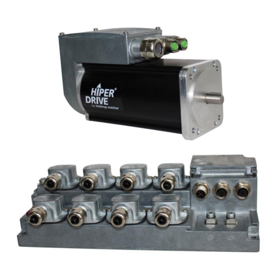
Hub itself, apart from the fieldbus and 24V motor supply voltage, only a 24V auxiliary voltage is required for the hub electronics. The HIPERDRIVE drives are equipped with a bus adapter. The bus adapter has a fixed connection to the drive. Each drive unit therefore has its own bus address and its own fieldbus connection. -
Page 7: Device Description: Hiperdrive Hub
Screw terminal for each of the drives connected to the HIPERDRIVE Hub: For each drive to be connected to the HIPERDRIVE Hub, there is a flange adapter containing a screw terminal with the following pin assignment: Signal... -
Page 8: Setting The Device Address
“configured station alias” can be defined using the two rotary switches (address switch value > 0). LEDs and jog keys for the HIPERDRIVE Hub Opening the housing cover on the top side of the hub provides access to the following... - Page 9 SDO #208F (jog 1; default 1/16 rotation forwards) Important: Always close the housing cover after completing the operating and observation task. This will prevent dust and contaminants from entering the device. The HIPERDRIVE drives can only be run via the bus if S3 is set to 0.
-
Page 10: Meaning Of The Led Statuses Of Led "Rs485
The LED RS485 shows a collective message. When switch S3 is set to 0, the meanings are as follows: Status Meaning No power supply to the HIPERDRIVE electronics. flashes Presence test red+green The hub is detecting the ports to which drive are connected... -
Page 11: Start-Up: Hiperdrive Hub
Instruction Manual HIPERDRIVE with EtherCAT Start-up: HIPERDRIVE Hub After connecting the supply voltage, the hub automatically performs a presence test. During this test, the hub detects the ports to which drives are connected. For each drive, the baud rate is set to the last value saved in the hub for the specific drive. The “RS485 message complete time”... -
Page 12: Device Description: Hiperdrive Bus Adapter
Pin assignment: HIPERDRIVE bus adapter A 4-pin screw terminal for connecting the supply voltage is located in the housing cover of the HIPERDRIVE bus adapter. A PG threaded connection through which the screw terminal can be accessed is provided as standard. Optionally, these terminals are already factory-wired to the pins of a 7/8″... -
Page 13: Setting The Device Address
Instruction Manual HIPERDRIVE with EtherCAT The former is generally selected if the motor power supply is run in a safety circuit with the EMERGENCY STOP and the databus has to remain active during an EMERGENCY STOP, or if the motor power supply does not permit correct operation of the bus adapter due to inadequate voltage stability or high interference voltages. -
Page 14: Leds For The Hiperdrive Bus Adapter
Instruction Manual HIPERDRIVE with EtherCAT LEDs for the HIPERDRIVE bus adapter Opening the cover of the bus adapter provides access to the following operating and observation elements: The LEDs are visible through two windows even when the bus adapter cover is closed. -
Page 15: Meaning Of The Led Statuses Of Led "Rs485
Meaning of the LED statuses of LED “RS485” LED-RS485 shows a collective message. Status Meaning No power supply to the HIPERDRIVE electronics. flashes Presence test red+green The bus adapter determines whether communication with the alternately basic unit has been established. -
Page 16: The Ethercat Interface
Instruction Manual HIPERDRIVE with EtherCAT 5 The EtherCAT interface EtherCAT interface with CoE protocol (CANopen over EtherCAT) The EtherCAT interface uses the CANopen over EtherCAT protocol in accordance with ETG1000.6 Section 5.6: one send and one receive SDO per device ... -
Page 17: Table Of Entries Implemented From Object Dictionary
The area 0x1000 to 0x207F of the object dictionary contains those objects that only exist once regardless of whether the HIPERDRIVE unit is a drive with a bus adapter or a hub and independently of the number of drives that can be connected to a hub. - Page 18 Instruction Manual HIPERDRIVE with EtherCAT Name, Index Function Range of Back Deliver designation number values y state Transmit 1A00 Sub index 0: No. of indices 8 bit (Adapter 3; Hub-4 12; Hub-8 24) PDO 1 mapping Sub 1: 0x20840010...
- Page 19 Instruction Manual HIPERDRIVE with EtherCAT Name, Index Function Range of Back Delivery designation number values state general 2000 10 general purpose registers purpose Sub index 0: No. of indices (= 10) 8 bit register Sub 1..10: Free register 32 bit...
- Page 20 (during writing) 0..3 The execution of this command may take (during up to 2 sec for the HIPERDRIVE bus reading) adapter and up to 8 sec for the 15 bit HIPERDRIVE Hub Watch acknowledgement of drive (receiving of SDO response).
- Page 21 Instruction Manual HIPERDRIVE with EtherCAT For HIPERDRIVE Hubs, the following section is repeated for each additional drive: The area above 0x2080 of the object dictionary contains those objects that exist once for each connectable drive. The following table describes the SDOs for the first drive connected, i.e. drive 1 on the hub or the drive connected to the HIPERDRIVE bus adapter.
- Page 22 Instruction Manual HIPERDRIVE with EtherCAT Name, Index Function Range of Back Delivery designation number values state Fault buffer *) 2088 The most recent causes of faults or errors Sub index 0: No. of indices (= 8) 8 bit Sub 1: latest cause of error 16 bit …...
- Page 23 Instruction Manual HIPERDRIVE with EtherCAT Name, Index Function Range of Back Delivery designation number values state Position 208A Minimum The upper limit must be see table 31 bit lower limit permitted min. 1 higher than the lower table target limit.
- Page 24 Instruction Manual HIPERDRIVE with EtherCAT Name, Index Function Range of Back Delivery designation number values state 100… Idle period for 2091 Length of time a manual run key must be 1000 manual run held pressed in order to begin a manual...
- Page 25 Instruction Manual HIPERDRIVE with EtherCAT Name, Index Function Range of Back Delivery designation number values state Serial 209C Serial number of the drive as string number of the drive Production 209D Year and week of manufacture of the date of the...
- Page 26 Instruction Manual HIPERDRIVE with EtherCAT Name, Index Function Range of Back Delivery designation number values state Baud rate 20A3 RS485 baud rate of the drive 32 bit 38400 The values 9600, 19200 and 38400 are permitted. The appropriate value for the “message complete time”...
-
Page 27: Pdo Format
The following table describes the PDOs for the first drive connected, i.e. drive 1 on the hub or the drive connected to the HIPERDRIVE bus adapter. The PDO information for each additional drive (on the hub) is attached in each case, i.e. - Page 28 Instruction Manual HIPERDRIVE with EtherCAT Bit 2: Operation enabled This bit is set: - when bit 3 of the control word is set in the state “Ready for operation” (set control word to 0x0409) This bit is reset: - when bit 3 is reset...
-
Page 29: Detailed Description Of Control Bits
Instruction Manual HIPERDRIVE with EtherCAT Bit 10: Target position reached This bit is set: - when a drive has arrived at its target position This bit is reset: - at the beginning of a positioning run - when the state is less than “Ready for operation” (in the states “Fault” and “Switch on inhibit”, the bit initially retains its old value) - Page 30 Instruction Manual HIPERDRIVE with EtherCAT Bit 1: No OFF2 reserved, must be set to 0 Bit 2: No OFF3 reserved, must be set to 0 Bit 3: Operation enabled The drive goes from the state “Ready for operation” to the state “Operation enabled”...
- Page 31 Instruction Manual HIPERDRIVE with EtherCAT Bit 10: Control by the automation equipment The drive goes from the state “Not ready to Switch on” to the state “Ready to Switch on”. Bit 11: Start referencing Reserved, must be set to 0.
-
Page 32: Flow Chart
Instruction Manual HIPERDRIVE with EtherCAT Flow chart The following flow chart shows the possible states of a drive as well as the transitions between the states. Abbreviations used: STW = Control word ZSW = Status (“status word”) The requirement for each run is that the “percentaged target speed” and “percentaged maximum torque”... -
Page 33: Jog Function
Jog function with jog keys in the HIPERDRIVE Hub The two jog keys in the HIPERDRIVE Hub can always be used to run the drive selected using the switch S3 (located in the middle between the two jog keys) and independently of the PLC. -
Page 34: Special Features
Instruction Manual HIPERDRIVE with EtherCAT 7 Special features Target speed (r.p.m.) and torque These values are stated as a percentage of a reference value. The 100% value for the target speed (r.p.m.) is stated in SDO #208C (for drive 1), the 100% value for the target torque is fixed and is the same as the nominal torque for the drive. -
Page 35: Aborted Run When The Master Fails
Sync Manager Watchdog which is implemented in the EtherCAT master: If the HIPERDRIVE Hub or adapter does not receive a SYNC event within a specified time, it will command an... -
Page 36: Technical Data
Instruction Manual HIPERDRIVE with EtherCAT 8 Technical data HIPERDRIVE Hub Ambient conditions Ambient temperature 0 °C to +70 °C Storage temperature -25 °C to +75 °C Shock resistance as stipulated in 8 g / 50 ms DIN IEC 68-2-27 10 … 500 Hz: 10 g... -
Page 37: Drives With Hiperdrive Bus Adapter
4.8 A HDA 70 4.8 A Connection for supply voltage 4-pin screw terminal (either with separate or shared power supply with the HIPERDRIVE electronics and the motor) Max. cross section of conductor 1.5mm² Optional: 7/8″ plug Bus connection M12, 4-pin Type D (2 x) - Page 38 Instruction Manual HIPERDRIVE with EtherCAT Physical data Positioning range HDA 30, HDA 45: 1024 rotations HDA 70: 32000 rotations (no mechanical limits) Positioning accuracy max. ± 2.5° Repeat accuracy max. ± 1.0° type “S”: 10 mm solid circular shaft with feather key Output shaft type “H”: 12 mm hollow shaft...
-
Page 39: Certificate Of Conformity
Instruction Manual HIPERDRIVE with EtherCAT 9 Certificate of Conformity 7100.004854D_Hiperdrive_ECAT.doc 07/2018 Re...
Need help?
Do you have a question about the HIPERDRIVE and is the answer not in the manual?
Questions and answers